DODGE RAM 2003 Service Repair Manual
Manufacturer: DODGE, Model Year: 2003, Model line: RAM, Model: DODGE RAM 2003Pages: 2895, PDF Size: 83.15 MB
Page 271 of 2895
then opens the outlet valve, which also opens the
return circuit to the accumulators. Fluid pressure is
allowed to bleed off (decrease) as needed to prevent
wheel lock.
Once the period of high wheel slip has ended, the
CAB closes the outlet valve and begins a pressure
increase or hold cycle as needed.
PRESSURE HOLD
Both solenoid valves are closed in the pressure
hold cycle but only the inlet valve is energized. Fluid
apply pressure in the control channel is maintained
at a constant rate. The CAB maintains the hold cycle
until sensor inputs indicate a pressure change is nec-
essary.
PRESSURE INCREASE
The inlet valve is open and the outlet valve is
closed during the pressure increase cycle. The pres-
sure increase cycle is used to reapply thew brakes.
This cycle controls re-application of fluid apply pres-
sure.
REMOVAL
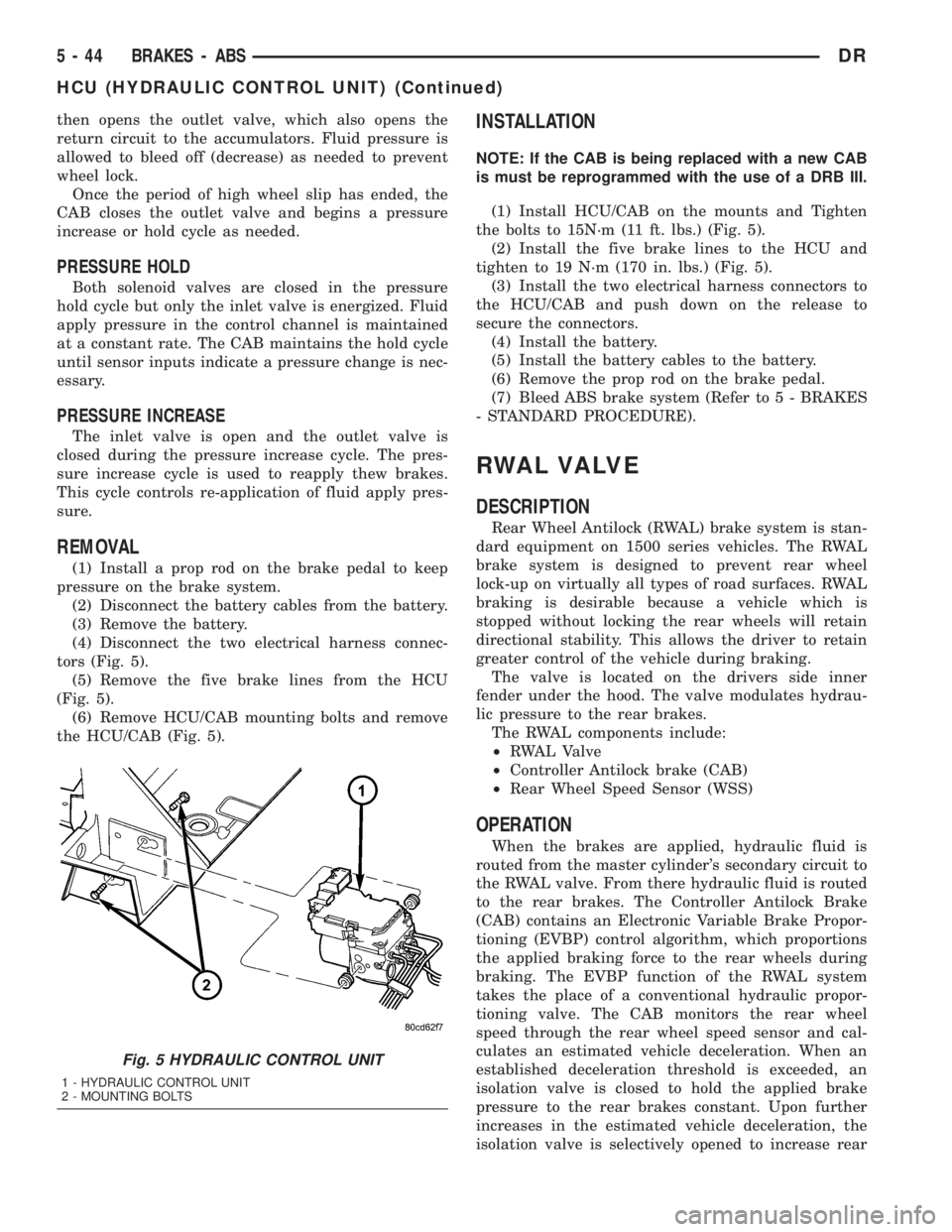
(1) Install a prop rod on the brake pedal to keep
pressure on the brake system.
(2) Disconnect the battery cables from the battery.
(3) Remove the battery.
(4) Disconnect the two electrical harness connec-
tors (Fig. 5).
(5) Remove the five brake lines from the HCU
(Fig. 5).
(6) Remove HCU/CAB mounting bolts and remove
the HCU/CAB (Fig. 5).
INSTALLATION
NOTE: If the CAB is being replaced with a new CAB
is must be reprogrammed with the use of a DRB III.
(1) Install HCU/CAB on the mounts and Tighten
the bolts to 15N´m (11 ft. lbs.) (Fig. 5).
(2) Install the five brake lines to the HCU and
tighten to 19 N´m (170 in. lbs.) (Fig. 5).
(3) Install the two electrical harness connectors to
the HCU/CAB and push down on the release to
secure the connectors.
(4) Install the battery.
(5) Install the battery cables to the battery.
(6) Remove the prop rod on the brake pedal.
(7) Bleed ABS brake system (Refer to 5 - BRAKES
- STANDARD PROCEDURE).
RWAL VALVE
DESCRIPTION
Rear Wheel Antilock (RWAL) brake system is stan-
dard equipment on 1500 series vehicles. The RWAL
brake system is designed to prevent rear wheel
lock-up on virtually all types of road surfaces. RWAL
braking is desirable because a vehicle which is
stopped without locking the rear wheels will retain
directional stability. This allows the driver to retain
greater control of the vehicle during braking.
The valve is located on the drivers side inner
fender under the hood. The valve modulates hydrau-
lic pressure to the rear brakes.
The RWAL components include:
²RWAL Valve
²Controller Antilock brake (CAB)
²Rear Wheel Speed Sensor (WSS)
OPERATION
When the brakes are applied, hydraulic fluid is
routed from the master cylinder's secondary circuit to
the RWAL valve. From there hydraulic fluid is routed
to the rear brakes. The Controller Antilock Brake
(CAB) contains an Electronic Variable Brake Propor-
tioning (EVBP) control algorithm, which proportions
the applied braking force to the rear wheels during
braking. The EVBP function of the RWAL system
takes the place of a conventional hydraulic propor-
tioning valve. The CAB monitors the rear wheel
speed through the rear wheel speed sensor and cal-
culates an estimated vehicle deceleration. When an
established deceleration threshold is exceeded, an
isolation valve is closed to hold the applied brake
pressure to the rear brakes constant. Upon further
increases in the estimated vehicle deceleration, the
isolation valve is selectively opened to increase rear
Fig. 5 HYDRAULIC CONTROL UNIT
1 - HYDRAULIC CONTROL UNIT
2 - MOUNTING BOLTS
5 - 44 BRAKES - ABSDR
HCU (HYDRAULIC CONTROL UNIT) (Continued)
Page 272 of 2895
brake pressure in proportion to the front brake pres-
sure. If impending rear wheel lock-up is sensed, the
CAB signals the RWAL valve to modulate hydraulic
brake pressure to the rear wheels to prevent lock-up.
NORMAL BRAKING Since the RWAL valve also
performs the EVBP or proportioning function, vehicle
deceleration under normal braking may be sufficient
to trigger the EVBP function of the RWAL system
without full RWAL activity as would normally occur
during an impending rear wheel lock-up. As previ-
ously mentioned, the isolation valve is selectively
closed and opened to increase rear brake pressure in
proportion to the front brake pressure under EVBP
control. Slight brake pedal pulsations may be noticed
as the isolation valve is opened.
REMOVAL
(1) Install a prop rod on the brake pedal to keep
pressure on the brake system.
(2) Disconnect the battery cables from the battery.
(3) Remove the battery.
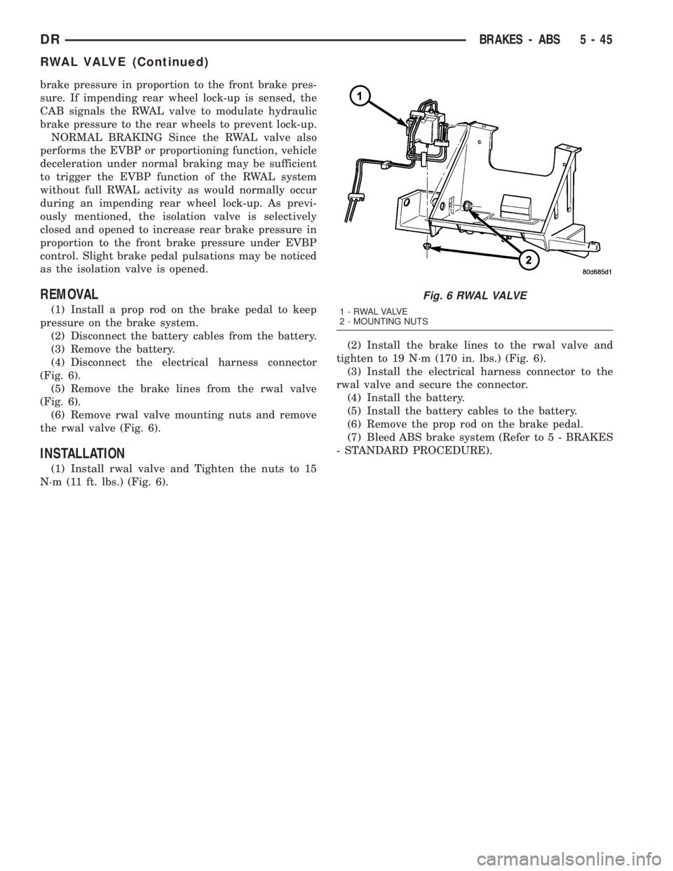
(4) Disconnect the electrical harness connector
(Fig. 6).
(5) Remove the brake lines from the rwal valve
(Fig. 6).
(6) Remove rwal valve mounting nuts and remove
the rwal valve (Fig. 6).
INSTALLATION
(1) Install rwal valve and Tighten the nuts to 15
N´m (11 ft. lbs.) (Fig. 6).(2) Install the brake lines to the rwal valve and
tighten to 19 N´m (170 in. lbs.) (Fig. 6).
(3) Install the electrical harness connector to the
rwal valve and secure the connector.
(4) Install the battery.
(5) Install the battery cables to the battery.
(6) Remove the prop rod on the brake pedal.
(7) Bleed ABS brake system (Refer to 5 - BRAKES
- STANDARD PROCEDURE).
Fig. 6 RWAL VALVE
1 - RWAL VALVE
2 - MOUNTING NUTS
DRBRAKES - ABS 5 - 45
RWAL VALVE (Continued)
Page 273 of 2895

Page 274 of 2895
CLUTCH
TABLE OF CONTENTS
page page
CLUTCH
DESCRIPTION..........................1
OPERATION............................1
WARNING.............................2
DIAGNOSIS AND TESTING................2
SPECIFICATIONS........................6
CLUTCH DISC
REMOVAL.............................6
INSTALLATION..........................6
CLUTCH HOUSING
DIAGNOSIS AND TESTING................8
REMOVAL.............................10
INSTALLATION.........................10
CLUTCH RELEASE BEARING
REMOVAL.............................11
INSTALLATION.........................11FLYWHEEL
DIAGNOSIS AND TESTING................11
REMOVAL.............................12
DISASSEMBLY.........................12
ASSEMBLY............................12
INSTALLATION.........................12
PILOT BEARING
REMOVAL.............................12
INSTALLATION.........................12
LINKAGE
REMOVAL.............................13
INSTALLATION.........................13
CLUTCH PEDAL POSITION SWITCH
DESCRIPTION.........................14
OPERATION...........................14
DIAGNOSIS AND TESTING................14
CLUTCH
DESCRIPTION
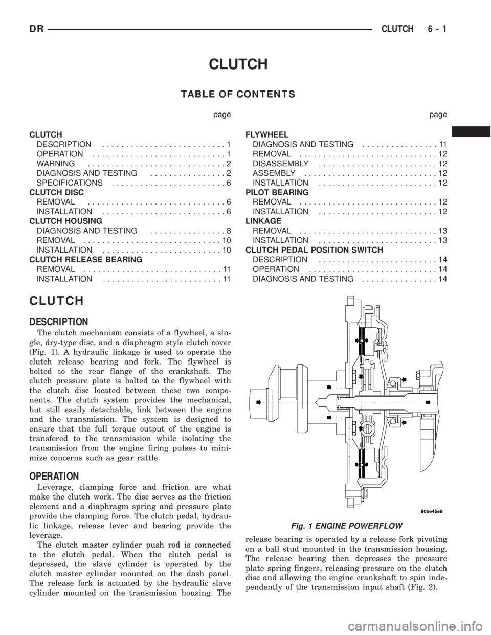
The clutch mechanism consists of a flywheel, a sin-
gle, dry-type disc, and a diaphragm style clutch cover
(Fig. 1). A hydraulic linkage is used to operate the
clutch release bearing and fork. The flywheel is
bolted to the rear flange of the crankshaft. The
clutch pressure plate is bolted to the flywheel with
the clutch disc located between these two compo-
nents. The clutch system provides the mechanical,
but still easily detachable, link between the engine
and the transmission. The system is designed to
ensure that the full torque output of the engine is
transfered to the transmission while isolating the
transmission from the engine firing pulses to mini-
mize concerns such as gear rattle.
OPERATION
Leverage, clamping force and friction are what
make the clutch work. The disc serves as the friction
element and a diaphragm spring and pressure plate
provide the clamping force. The clutch pedal, hydrau-
lic linkage, release lever and bearing provide the
leverage.
The clutch master cylinder push rod is connected
to the clutch pedal. When the clutch pedal is
depressed, the slave cylinder is operated by the
clutch master cylinder mounted on the dash panel.
The release fork is actuated by the hydraulic slave
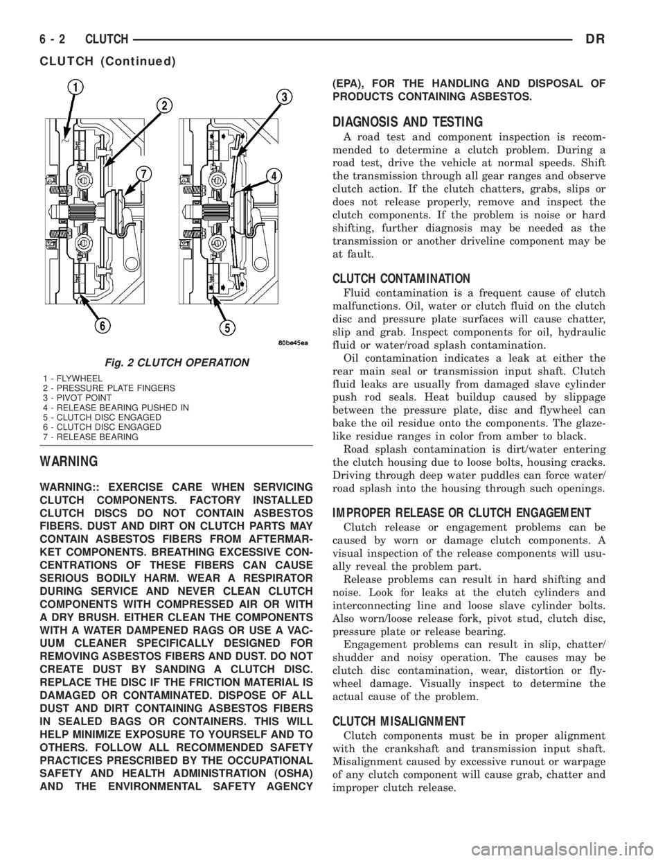
cylinder mounted on the transmission housing. Therelease bearing is operated by a release fork pivoting
on a ball stud mounted in the transmission housing.
The release bearing then depresses the pressure
plate spring fingers, releasing pressure on the clutch
disc and allowing the engine crankshaft to spin inde-
pendently of the transmission input shaft (Fig. 2).
Fig. 1 ENGINE POWERFLOW
DRCLUTCH 6 - 1
Page 275 of 2895
WARNING
WARNING:: EXERCISE CARE WHEN SERVICING
CLUTCH COMPONENTS. FACTORY INSTALLED
CLUTCH DISCS DO NOT CONTAIN ASBESTOS
FIBERS. DUST AND DIRT ON CLUTCH PARTS MAY
CONTAIN ASBESTOS FIBERS FROM AFTERMAR-
KET COMPONENTS. BREATHING EXCESSIVE CON-
CENTRATIONS OF THESE FIBERS CAN CAUSE
SERIOUS BODILY HARM. WEAR A RESPIRATOR
DURING SERVICE AND NEVER CLEAN CLUTCH
COMPONENTS WITH COMPRESSED AIR OR WITH
A DRY BRUSH. EITHER CLEAN THE COMPONENTS
WITH A WATER DAMPENED RAGS OR USE A VAC-
UUM CLEANER SPECIFICALLY DESIGNED FOR
REMOVING ASBESTOS FIBERS AND DUST. DO NOT
CREATE DUST BY SANDING A CLUTCH DISC.
REPLACE THE DISC IF THE FRICTION MATERIAL IS
DAMAGED OR CONTAMINATED. DISPOSE OF ALL
DUST AND DIRT CONTAINING ASBESTOS FIBERS
IN SEALED BAGS OR CONTAINERS. THIS WILL
HELP MINIMIZE EXPOSURE TO YOURSELF AND TO
OTHERS. FOLLOW ALL RECOMMENDED SAFETY
PRACTICES PRESCRIBED BY THE OCCUPATIONAL
SAFETY AND HEALTH ADMINISTRATION (OSHA)
AND THE ENVIRONMENTAL SAFETY AGENCY(EPA), FOR THE HANDLING AND DISPOSAL OF
PRODUCTS CONTAINING ASBESTOS.
DIAGNOSIS AND TESTING
A road test and component inspection is recom-
mended to determine a clutch problem. During a
road test, drive the vehicle at normal speeds. Shift
the transmission through all gear ranges and observe
clutch action. If the clutch chatters, grabs, slips or
does not release properly, remove and inspect the
clutch components. If the problem is noise or hard
shifting, further diagnosis may be needed as the
transmission or another driveline component may be
at fault.
CLUTCH CONTAMINATION
Fluid contamination is a frequent cause of clutch
malfunctions. Oil, water or clutch fluid on the clutch
disc and pressure plate surfaces will cause chatter,
slip and grab. Inspect components for oil, hydraulic
fluid or water/road splash contamination.
Oil contamination indicates a leak at either the
rear main seal or transmission input shaft. Clutch
fluid leaks are usually from damaged slave cylinder
push rod seals. Heat buildup caused by slippage
between the pressure plate, disc and flywheel can
bake the oil residue onto the components. The glaze-
like residue ranges in color from amber to black.
Road splash contamination is dirt/water entering
the clutch housing due to loose bolts, housing cracks.
Driving through deep water puddles can force water/
road splash into the housing through such openings.
IMPROPER RELEASE OR CLUTCH ENGAGEMENT
Clutch release or engagement problems can be
caused by worn or damage clutch components. A
visual inspection of the release components will usu-
ally reveal the problem part.
Release problems can result in hard shifting and
noise. Look for leaks at the clutch cylinders and
interconnecting line and loose slave cylinder bolts.
Also worn/loose release fork, pivot stud, clutch disc,
pressure plate or release bearing.
Engagement problems can result in slip, chatter/
shudder and noisy operation. The causes may be
clutch disc contamination, wear, distortion or fly-
wheel damage. Visually inspect to determine the
actual cause of the problem.
CLUTCH MISALIGNMENT
Clutch components must be in proper alignment
with the crankshaft and transmission input shaft.
Misalignment caused by excessive runout or warpage
of any clutch component will cause grab, chatter and
improper clutch release.
Fig. 2 CLUTCH OPERATION
1 - FLYWHEEL
2 - PRESSURE PLATE FINGERS
3 - PIVOT POINT
4 - RELEASE BEARING PUSHED IN
5 - CLUTCH DISC ENGAGED
6 - CLUTCH DISC ENGAGED
7 - RELEASE BEARING
6 - 2 CLUTCHDR
CLUTCH (Continued)
Page 276 of 2895
CLUTCH COVER AND DISC RUNOUT
Check the clutch disc before installation. Axial
(face) runout of anewdisc should not exceed 0.50
mm (0.020 in.). Measure runout about 6 mm (1/4 in.)
from the outer edge of the disc facing. Obtain
another disc if runout is excessive.
Check condition of the clutch before installation. A
warped cover or diaphragm spring will cause grab
and incomplete release or engagement. Be careful
when handling the cover and disc. Impact can distort
the cover, diaphragm spring, release fingers and the
hub of the clutch disc.
Use an alignment tool when positioning the disc on
the flywheel. The tool prevents accidental misalign-
ment which could result in cover distortion and disc
damage.
A frequent cause of clutch cover distortion (and
consequent misalignment) is improper bolt tighten-
ing.
FLYWHEEL RUNOUT
Check flywheel runout whenever misalignment is
suspected. Flywheel runout should not exceed 0.08
mm (0.003 in.). Measure runout at the outer edge of
the flywheel face with a dial indicator.
Common causes of runout are:
²heat warpage
²improper machining
²incorrect bolt tightening
²improper seating on crankshaft flange shoulder²foreign material on crankshaft flange
Flywheel machining is not recommended. The fly-
wheel clutch surface is machined to a unique contour
and machining will negate this feature. Minor fly-
wheel scoring can be cleaned up by hand with 180
grit emery or with turning equipment. Remove only
enough material to reduce scoring (approximately
0.001 - 0.003 in.). Heavy stock removal isnot rec-
ommended.Replace the flywheel if scoring is severe
and deeper than 0.076 mm (0.003 in.). Excessive
stock removal can result in flywheel cracking or
warpage after installation; it can also weaken the fly-
wheel and interfere with proper clutch release.
Clean the crankshaft flange before mounting the
flywheel. Dirt and grease on the flange surface may
cock the flywheel causing excessive runout. Use new
bolts when remounting a flywheel and secure the
bolts with Mopar Lock And Seal or equivalent.
Tighten flywheel bolts to specified torque only. Over-
tightening can distort the flywheel hub causing
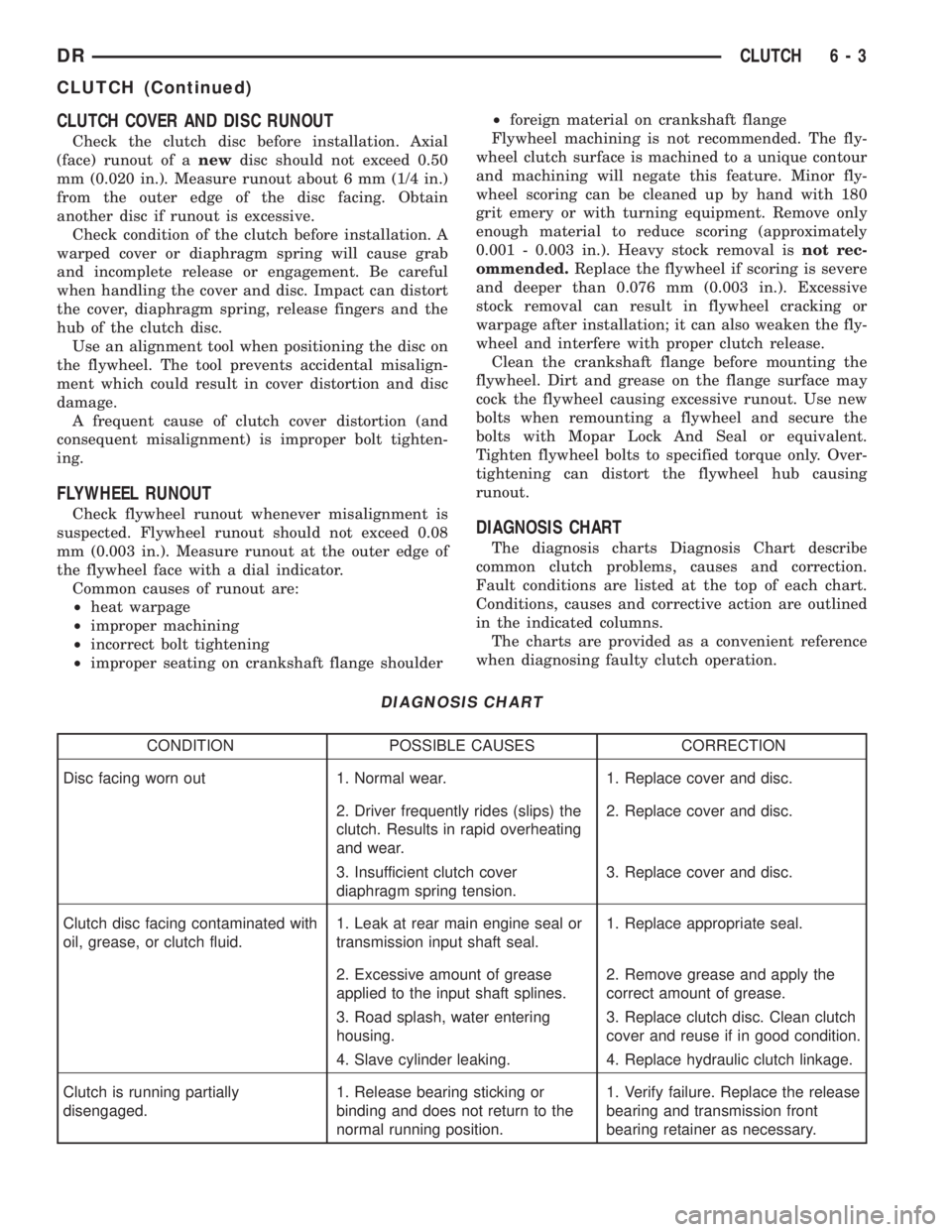
runout.DIAGNOSIS CHART
The diagnosis charts Diagnosis Chart describe
common clutch problems, causes and correction.
Fault conditions are listed at the top of each chart.
Conditions, causes and corrective action are outlined
in the indicated columns.
The charts are provided as a convenient reference
when diagnosing faulty clutch operation.
DIAGNOSIS CHART
CONDITION POSSIBLE CAUSES CORRECTION
Disc facing worn out 1. Normal wear. 1. Replace cover and disc.
2. Driver frequently rides (slips) the
clutch. Results in rapid overheating
and wear.2. Replace cover and disc.
3. Insufficient clutch cover
diaphragm spring tension.3. Replace cover and disc.
Clutch disc facing contaminated with
oil, grease, or clutch fluid.1. Leak at rear main engine seal or
transmission input shaft seal.1. Replace appropriate seal.
2. Excessive amount of grease
applied to the input shaft splines.2. Remove grease and apply the
correct amount of grease.
3. Road splash, water entering
housing.3. Replace clutch disc. Clean clutch
cover and reuse if in good condition.
4. Slave cylinder leaking. 4. Replace hydraulic clutch linkage.
Clutch is running partially
disengaged.1. Release bearing sticking or
binding and does not return to the
normal running position.1. Verify failure. Replace the release
bearing and transmission front
bearing retainer as necessary.
DRCLUTCH 6 - 3
CLUTCH (Continued)
Page 277 of 2895
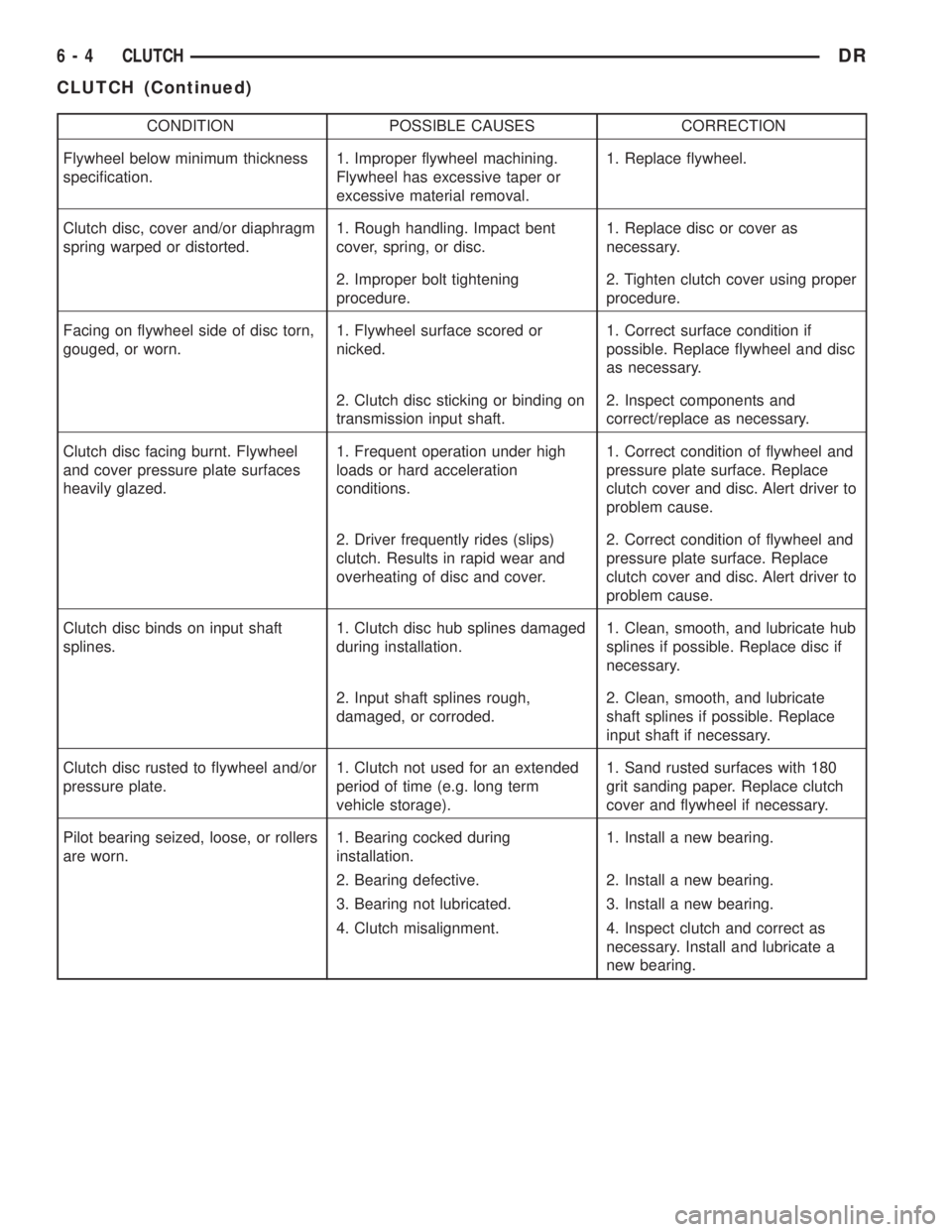
CONDITION POSSIBLE CAUSES CORRECTION
Flywheel below minimum thickness
specification.1. Improper flywheel machining.
Flywheel has excessive taper or
excessive material removal.1. Replace flywheel.
Clutch disc, cover and/or diaphragm
spring warped or distorted.1. Rough handling. Impact bent
cover, spring, or disc.1. Replace disc or cover as
necessary.
2. Improper bolt tightening
procedure.2. Tighten clutch cover using proper
procedure.
Facing on flywheel side of disc torn,
gouged, or worn.1. Flywheel surface scored or
nicked.1. Correct surface condition if
possible. Replace flywheel and disc
as necessary.
2. Clutch disc sticking or binding on
transmission input shaft.2. Inspect components and
correct/replace as necessary.
Clutch disc facing burnt. Flywheel
and cover pressure plate surfaces
heavily glazed.1. Frequent operation under high
loads or hard acceleration
conditions.1. Correct condition of flywheel and
pressure plate surface. Replace
clutch cover and disc. Alert driver to
problem cause.
2. Driver frequently rides (slips)
clutch. Results in rapid wear and
overheating of disc and cover.2. Correct condition of flywheel and
pressure plate surface. Replace
clutch cover and disc. Alert driver to
problem cause.
Clutch disc binds on input shaft
splines.1. Clutch disc hub splines damaged
during installation.1. Clean, smooth, and lubricate hub
splines if possible. Replace disc if
necessary.
2. Input shaft splines rough,
damaged, or corroded.2. Clean, smooth, and lubricate
shaft splines if possible. Replace
input shaft if necessary.
Clutch disc rusted to flywheel and/or
pressure plate.1. Clutch not used for an extended
period of time (e.g. long term
vehicle storage).1. Sand rusted surfaces with 180
grit sanding paper. Replace clutch
cover and flywheel if necessary.
Pilot bearing seized, loose, or rollers
are worn.1. Bearing cocked during
installation.1. Install a new bearing.
2. Bearing defective. 2. Install a new bearing.
3. Bearing not lubricated. 3. Install a new bearing.
4. Clutch misalignment. 4. Inspect clutch and correct as
necessary. Install and lubricate a
new bearing.
6 - 4 CLUTCHDR
CLUTCH (Continued)
Page 278 of 2895
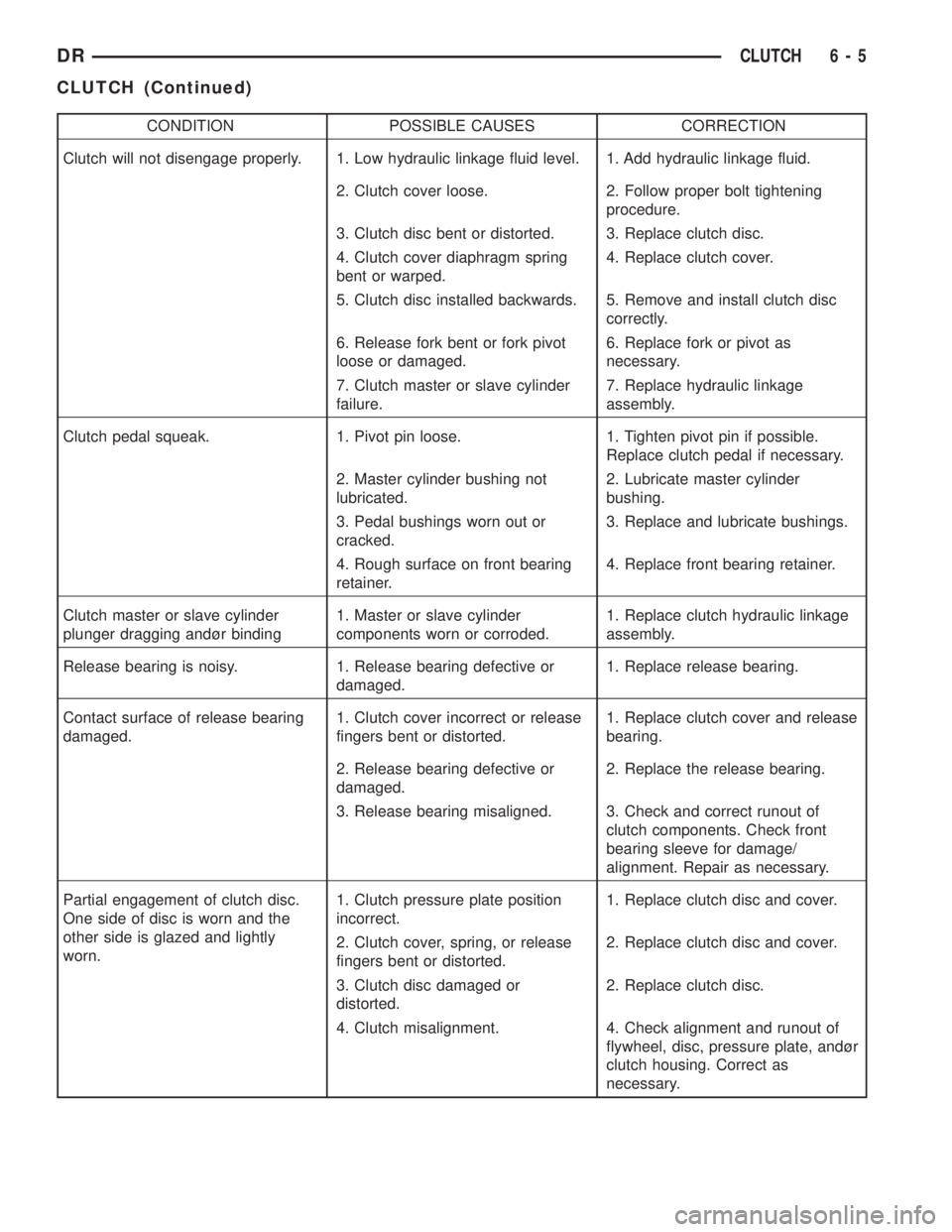
CONDITION POSSIBLE CAUSES CORRECTION
Clutch will not disengage properly. 1. Low hydraulic linkage fluid level. 1. Add hydraulic linkage fluid.
2. Clutch cover loose. 2. Follow proper bolt tightening
procedure.
3. Clutch disc bent or distorted. 3. Replace clutch disc.
4. Clutch cover diaphragm spring
bent or warped.4. Replace clutch cover.
5. Clutch disc installed backwards. 5. Remove and install clutch disc
correctly.
6. Release fork bent or fork pivot
loose or damaged.6. Replace fork or pivot as
necessary.
7. Clutch master or slave cylinder
failure.7. Replace hydraulic linkage
assembly.
Clutch pedal squeak. 1. Pivot pin loose. 1. Tighten pivot pin if possible.
Replace clutch pedal if necessary.
2. Master cylinder bushing not
lubricated.2. Lubricate master cylinder
bushing.
3. Pedal bushings worn out or
cracked.3. Replace and lubricate bushings.
4. Rough surface on front bearing
retainer.4. Replace front bearing retainer.
Clutch master or slave cylinder
plunger dragging andùr binding1. Master or slave cylinder
components worn or corroded.1. Replace clutch hydraulic linkage
assembly.
Release bearing is noisy. 1. Release bearing defective or
damaged.1. Replace release bearing.
Contact surface of release bearing
damaged.1. Clutch cover incorrect or release
fingers bent or distorted.1. Replace clutch cover and release
bearing.
2. Release bearing defective or
damaged.2. Replace the release bearing.
3. Release bearing misaligned. 3. Check and correct runout of
clutch components. Check front
bearing sleeve for damage/
alignment. Repair as necessary.
Partial engagement of clutch disc.
One side of disc is worn and the
other side is glazed and lightly
worn.1. Clutch pressure plate position
incorrect.1. Replace clutch disc and cover.
2. Clutch cover, spring, or release
fingers bent or distorted.2. Replace clutch disc and cover.
3. Clutch disc damaged or
distorted.2. Replace clutch disc.
4. Clutch misalignment. 4. Check alignment and runout of
flywheel, disc, pressure plate, andùr
clutch housing. Correct as
necessary.
DRCLUTCH 6 - 5
CLUTCH (Continued)
Page 279 of 2895
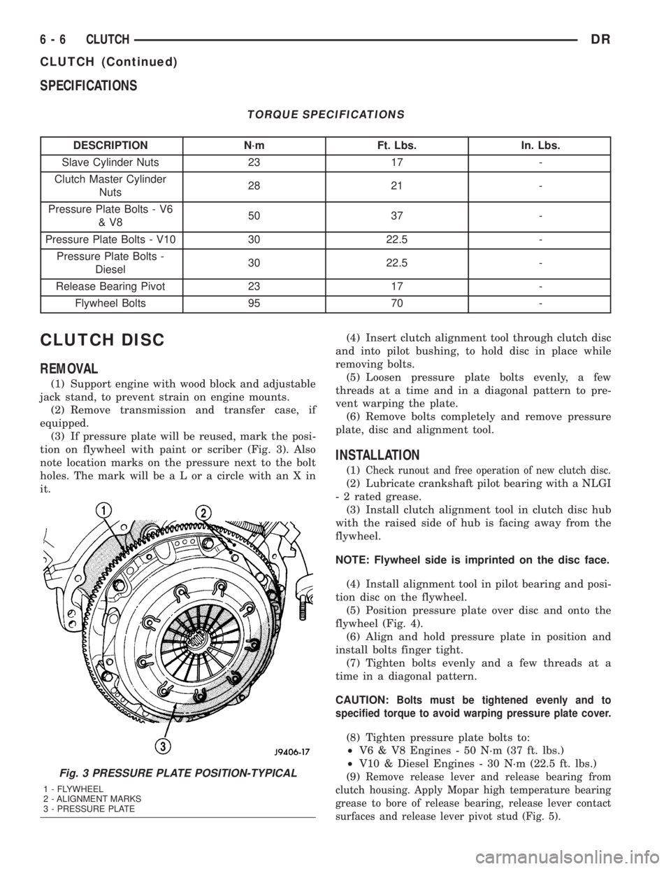
SPECIFICATIONS
TORQUE SPECIFICATIONS
DESCRIPTION N´m Ft. Lbs. In. Lbs.
Slave Cylinder Nuts 23 17 -
Clutch Master Cylinder
Nuts28 21 -
Pressure Plate Bolts - V6
&V850 37 -
Pressure Plate Bolts - V10 30 22.5 -
Pressure Plate Bolts -
Diesel30 22.5 -
Release Bearing Pivot 23 17 -
Flywheel Bolts 95 70 -
CLUTCH DISC
REMOVAL
(1) Support engine with wood block and adjustable
jack stand, to prevent strain on engine mounts.
(2) Remove transmission and transfer case, if
equipped.
(3) If pressure plate will be reused, mark the posi-
tion on flywheel with paint or scriber (Fig. 3). Also
note location marks on the pressure next to the bolt
holes. The mark will be a L or a circle with an X in
it.(4) Insert clutch alignment tool through clutch disc
and into pilot bushing, to hold disc in place while
removing bolts.
(5) Loosen pressure plate bolts evenly, a few
threads at a time and in a diagonal pattern to pre-
vent warping the plate.
(6) Remove bolts completely and remove pressure
plate, disc and alignment tool.
INSTALLATION
(1)Check runout and free operation of new clutch disc.
(2) Lubricate crankshaft pilot bearing with a NLGI
- 2 rated grease.
(3) Install clutch alignment tool in clutch disc hub
with the raised side of hub is facing away from the
flywheel.
NOTE: Flywheel side is imprinted on the disc face.
(4) Install alignment tool in pilot bearing and posi-
tion disc on the flywheel.
(5) Position pressure plate over disc and onto the
flywheel (Fig. 4).
(6) Align and hold pressure plate in position and
install bolts finger tight.
(7) Tighten bolts evenly and a few threads at a
time in a diagonal pattern.
CAUTION:
Bolts must be tightened evenly and to
specified torque to avoid warping pressure plate cover.
(8) Tighten pressure plate bolts to:
²V6 & V8 Engines - 50 N´m (37 ft. lbs.)
²V10 & Diesel Engines - 30 N´m (22.5 ft. lbs.)
(9)
Remove release lever and release bearing from
clutch housing. Apply Mopar high temperature bearing
grease to bore of release bearing, release lever contact
surfaces and release lever pivot stud (Fig. 5).Fig. 3 PRESSURE PLATE POSITION-TYPICAL
1 - FLYWHEEL
2 - ALIGNMENT MARKS
3 - PRESSURE PLATE
6 - 6 CLUTCHDR
CLUTCH (Continued)
Page 280 of 2895
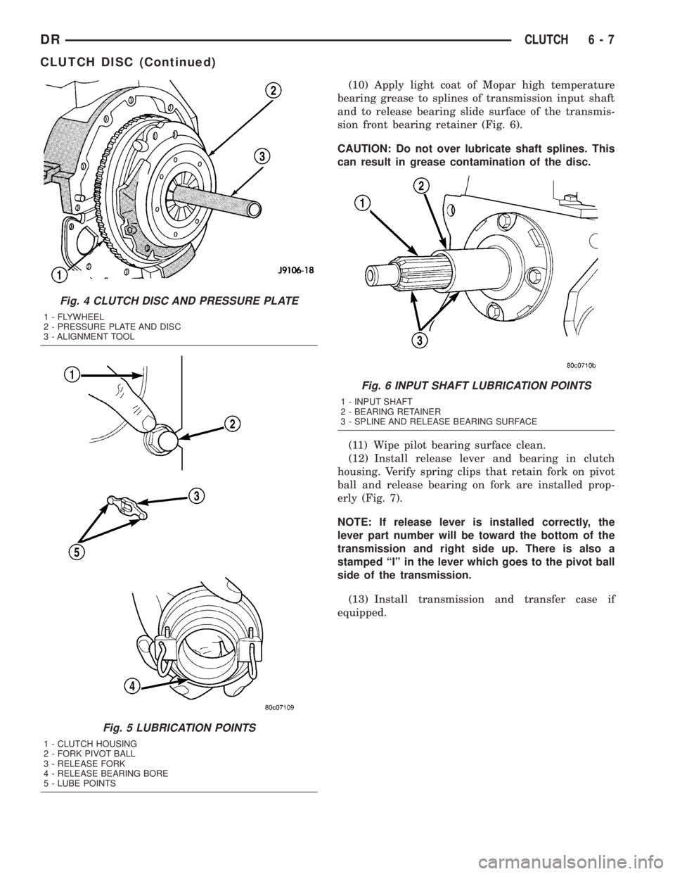
(10) Apply light coat of Mopar high temperature
bearing grease to splines of transmission input shaft
and to release bearing slide surface of the transmis-
sion front bearing retainer (Fig. 6).
CAUTION: Do not over lubricate shaft splines. This
can result in grease contamination of the disc.
(11) Wipe pilot bearing surface clean.
(12) Install release lever and bearing in clutch
housing. Verify spring clips that retain fork on pivot
ball and release bearing on fork are installed prop-
erly (Fig. 7).
NOTE: If release lever is installed correctly, the
lever part number will be toward the bottom of the
transmission and right side up. There is also a
stamped ªIº in the lever which goes to the pivot ball
side of the transmission.
(13) Install transmission and transfer case if
equipped.
Fig. 4 CLUTCH DISC AND PRESSURE PLATE
1 - FLYWHEEL
2 - PRESSURE PLATE AND DISC
3 - ALIGNMENT TOOL
Fig. 5 LUBRICATION POINTS
1 - CLUTCH HOUSING
2 - FORK PIVOT BALL
3 - RELEASE FORK
4 - RELEASE BEARING BORE
5 - LUBE POINTS
Fig. 6 INPUT SHAFT LUBRICATION POINTS
1 - INPUT SHAFT
2 - BEARING RETAINER
3 - SPLINE AND RELEASE BEARING SURFACE
DRCLUTCH 6 - 7
CLUTCH DISC (Continued)