DODGE RAM 2003 Service Repair Manual
Manufacturer: DODGE, Model Year: 2003, Model line: RAM, Model: DODGE RAM 2003Pages: 2895, PDF Size: 83.15 MB
Page 281 of 2895
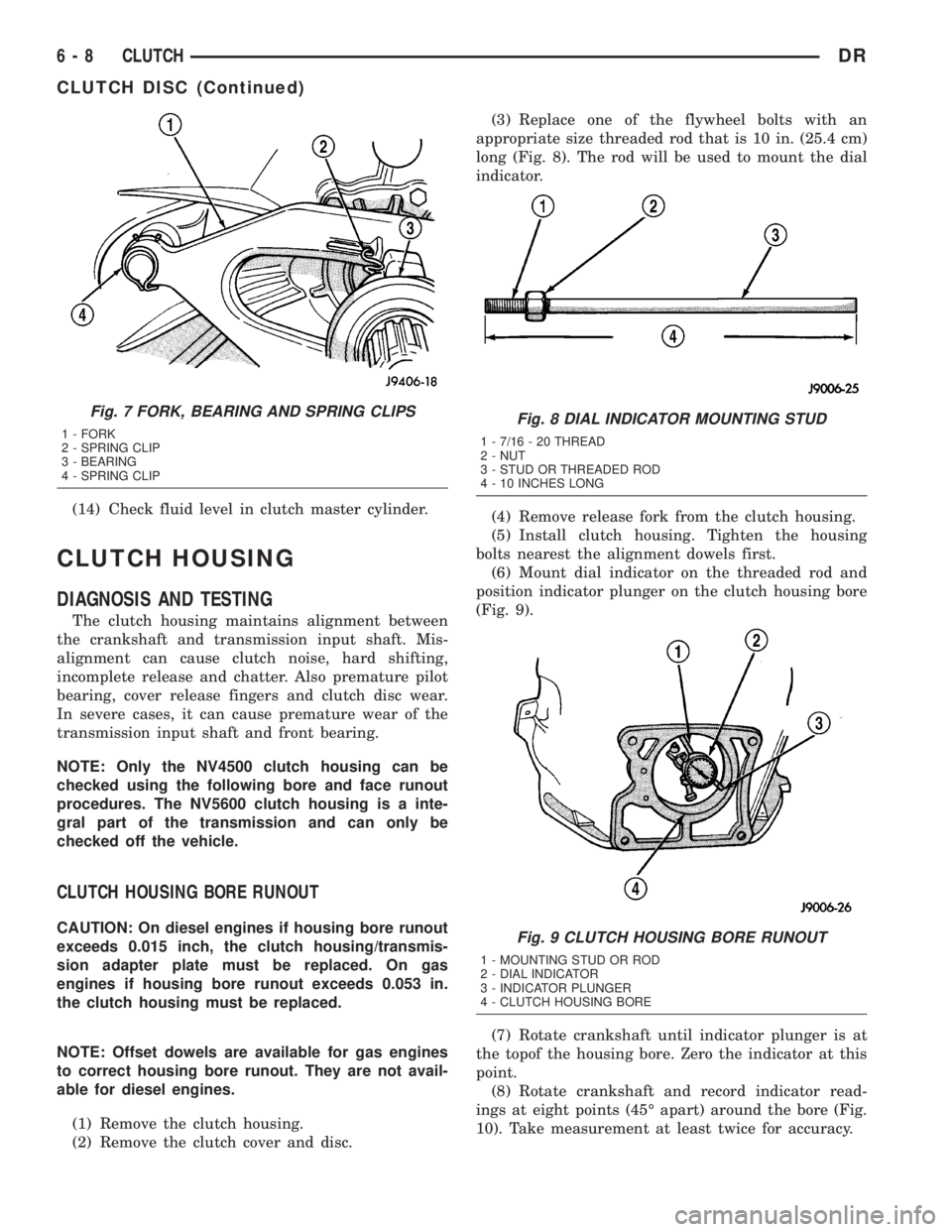
(14) Check fluid level in clutch master cylinder.
CLUTCH HOUSING
DIAGNOSIS AND TESTING
The clutch housing maintains alignment between
the crankshaft and transmission input shaft. Mis-
alignment can cause clutch noise, hard shifting,
incomplete release and chatter. Also premature pilot
bearing, cover release fingers and clutch disc wear.
In severe cases, it can cause premature wear of the
transmission input shaft and front bearing.
NOTE: Only the NV4500 clutch housing can be
checked using the following bore and face runout
procedures. The NV5600 clutch housing is a inte-
gral part of the transmission and can only be
checked off the vehicle.
CLUTCH HOUSING BORE RUNOUT
CAUTION: On diesel engines if housing bore runout
exceeds 0.015 inch, the clutch housing/transmis-
sion adapter plate must be replaced. On gas
engines if housing bore runout exceeds 0.053 in.
the clutch housing must be replaced.
NOTE: Offset dowels are available for gas engines
to correct housing bore runout. They are not avail-
able for diesel engines.
(1) Remove the clutch housing.
(2) Remove the clutch cover and disc.(3) Replace one of the flywheel bolts with an
appropriate size threaded rod that is 10 in. (25.4 cm)
long (Fig. 8). The rod will be used to mount the dial
indicator.
(4) Remove release fork from the clutch housing.
(5) Install clutch housing. Tighten the housing
bolts nearest the alignment dowels first.
(6) Mount dial indicator on the threaded rod and
position indicator plunger on the clutch housing bore
(Fig. 9).
(7) Rotate crankshaft until indicator plunger is at
the topof the housing bore. Zero the indicator at this
point.
(8) Rotate crankshaft and record indicator read-
ings at eight points (45É apart) around the bore (Fig.
10). Take measurement at least twice for accuracy.
Fig. 7 FORK, BEARING AND SPRING CLIPS
1 - FORK
2 - SPRING CLIP
3 - BEARING
4 - SPRING CLIPFig. 8 DIAL INDICATOR MOUNTING STUD
1 - 7/16 - 20 THREAD
2 - NUT
3 - STUD OR THREADED ROD
4 - 10 INCHES LONG
Fig. 9 CLUTCH HOUSING BORE RUNOUT
1 - MOUNTING STUD OR ROD
2 - DIAL INDICATOR
3 - INDICATOR PLUNGER
4 - CLUTCH HOUSING BORE
6 - 8 CLUTCHDR
CLUTCH DISC (Continued)
Page 282 of 2895
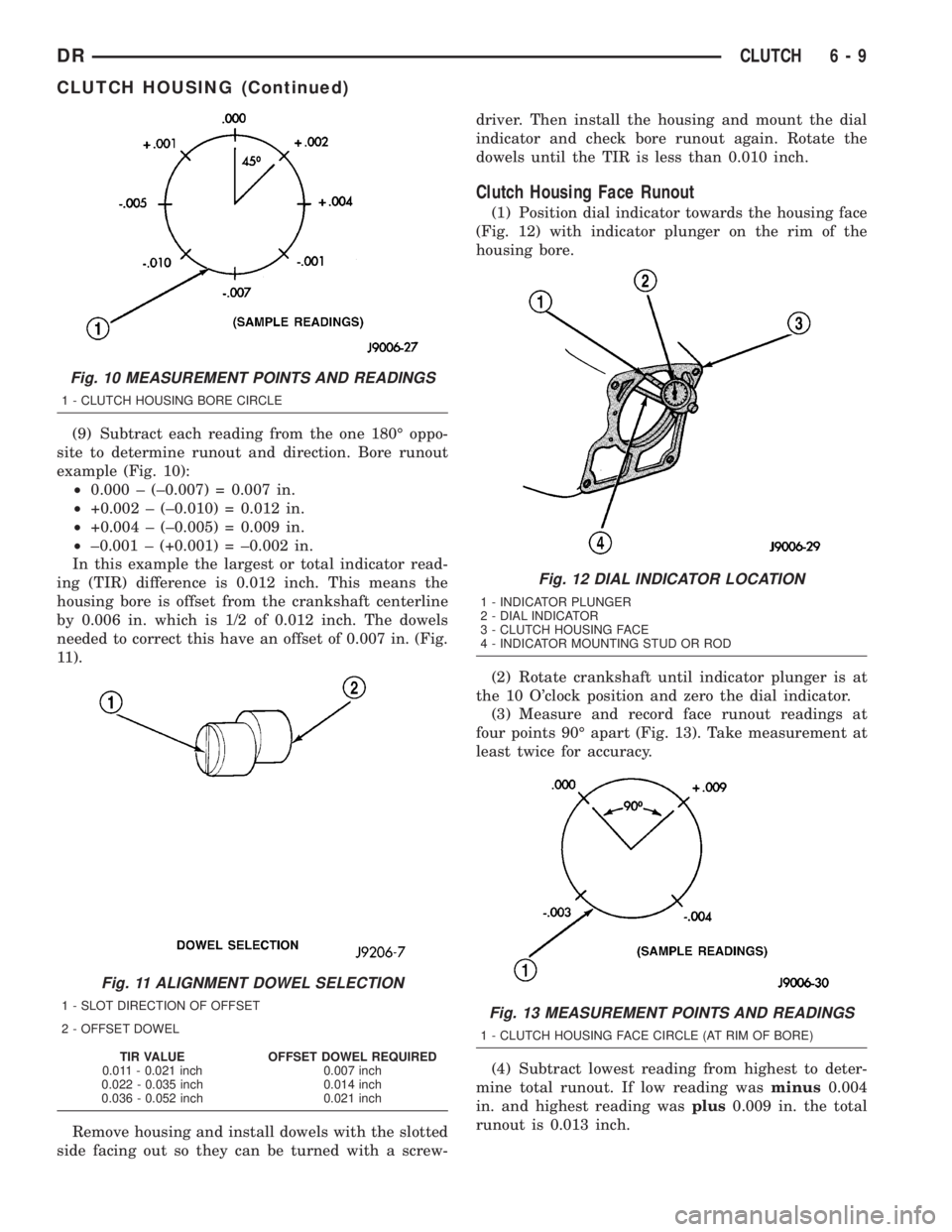
(9) Subtract each reading from the one 180É oppo-
site to determine runout and direction. Bore runout
example (Fig. 10):
²0.000 ± (±0.007) = 0.007 in.
²+0.002 ± (±0.010) = 0.012 in.
²+0.004 ± (±0.005) = 0.009 in.
²±0.001 ± (+0.001) = ±0.002 in.
In this example the largest or total indicator read-
ing (TIR) difference is 0.012 inch. This means the
housing bore is offset from the crankshaft centerline
by 0.006 in. which is 1/2 of 0.012 inch. The dowels
needed to correct this have an offset of 0.007 in. (Fig.
11).
Remove housing and install dowels with the slotted
side facing out so they can be turned with a screw-driver. Then install the housing and mount the dial
indicator and check bore runout again. Rotate the
dowels until the TIR is less than 0.010 inch.
Clutch Housing Face Runout
(1) Position dial indicator towards the housing face
(Fig. 12) with indicator plunger on the rim of the
housing bore.
(2) Rotate crankshaft until indicator plunger is at
the 10 O'clock position and zero the dial indicator.
(3) Measure and record face runout readings at
four points 90É apart (Fig. 13). Take measurement at
least twice for accuracy.
(4) Subtract lowest reading from highest to deter-
mine total runout. If low reading wasminus0.004
in. and highest reading wasplus0.009 in. the total
runout is 0.013 inch.
Fig. 10 MEASUREMENT POINTS AND READINGS
1 - CLUTCH HOUSING BORE CIRCLE
Fig. 11 ALIGNMENT DOWEL SELECTION
1 - SLOT DIRECTION OF OFFSET
2 - OFFSET DOWEL
TIR VALUE OFFSET DOWEL REQUIRED
0.011 - 0.021 inch 0.007 inch
0.022 - 0.035 inch 0.014 inch
0.036 - 0.052 inch 0.021 inch
Fig. 12 DIAL INDICATOR LOCATION
1 - INDICATOR PLUNGER
2 - DIAL INDICATOR
3 - CLUTCH HOUSING FACE
4 - INDICATOR MOUNTING STUD OR ROD
Fig. 13 MEASUREMENT POINTS AND READINGS
1 - CLUTCH HOUSING FACE CIRCLE (AT RIM OF BORE)
DRCLUTCH 6 - 9
CLUTCH HOUSING (Continued)
Page 283 of 2895
NOTE:Maximum acceptable face runout is 0.010 inch.
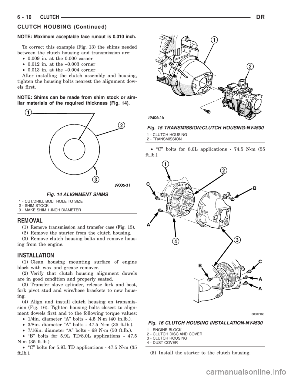
To correct this example (Fig. 13) the shims needed
between the clutch housing and transmission are:
²0.009 in. at the 0.000 corner
²0.012 in. at the ±0.003 corner
²0.013 in. at the ±0.004 corner
After installing the clutch assembly and housing,
tighten the housing bolts nearest the alignment dow-
els first.
NOTE: Shims can be made from shim stock or sim-
ilar materials of the required thickness (Fig. 14).
REMOVAL
(1)Remove transmission and transfer case (Fig. 15).
(2) Remove the starter from the clutch housing.
(3) Remove clutch housing bolts and remove hous-
ing from the engine.
INSTALLATION
(1) Clean housing mounting surface of engine
block with wax and grease remover.
(2) Verify that clutch housing alignment dowels
are in good condition and properly seated.
(3) Transfer slave cylinder, release fork and boot,
fork pivot stud and wire/hose brackets to new hous-
ing.
(4) Align and install clutch housing on transmis-
sion (Fig. 16). Tighten housing bolts closest to align-
ment dowels first and to the following torque values:
²1/4in. diameter ªAº bolts - 4.5 N´m (40 in.lb.).
²3/8in. diameter ªAº bolts - 47.5 N´m (35 ft.lb.).
²7/16in. diameter ªAº bolts - 68 N´m (50 ft.lb.).
²ªBº bolts for 5.9L TD/8.0L applications - 47.5
N´m (35 ft.lb.).
²ªCº bolts for 5.9L TD applications - 47.5 N´m (35
ft.lb.).²ªCº bolts for 8.0L applications - 74.5 N´m (55
ft.lb.).
(5) Install the starter to the clutch housing.
Fig. 14 ALIGNMENT SHIMS
1 - CUT/DRILL BOLT HOLE TO SIZE
2 - SHIM STOCK
3 - MAKE SHIM 1-INCH DIAMETER
Fig. 15 TRANSMISSION/CLUTCH HOUSING-NV4500
1 - CLUTCH HOUSING
2 - TRANSMISSION
Fig. 16 CLUTCH HOUSING INSTALLATION-NV4500
1 - ENGINE BLOCK
2 - CLUTCH DISC AND COVER
3 - CLUTCH HOUSING
4 - DUST COVER
6 - 10 CLUTCHDR
CLUTCH HOUSING (Continued)
Page 284 of 2895
(6) Install the clutch housing dust shield to the
clutch housing.
(7) Install transmission and transfer case, if
equipped.
CLUTCH RELEASE BEARING
REMOVAL
(1) Remove transmission and transfer case, if
equipped.
(2) Remove spring clip.
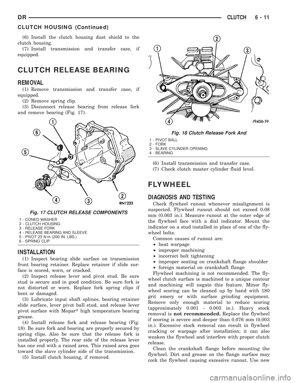
(3) Disconnect release bearing from release fork
and remove bearing (Fig. 17).
INSTALLATION
(1) Inspect bearing slide surface on transmission
front bearing retainer. Replace retainer if slide sur-
face is scored, worn, or cracked.
(2) Inspect release lever and pivot stud. Be sure
stud is secure and in good condition. Be sure fork is
not distorted or worn. Replace fork spring clips if
bent or damaged.
(3) Lubricate input shaft splines, bearing retainer
slide surface, lever pivot ball stud, and release lever
pivot surface with Moparthigh temperature bearing
grease.
(4) Install release fork and release bearing (Fig.
18). Be sure fork and bearing are properly secured by
spring clips. Also be sure that the release fork is
installed properly. The rear side of the release lever
has one end with a raised area. This raised area goes
toward the slave cylinder side of the transmission.
(5) Install clutch housing, if removed.(6) Install transmission and transfer case.
(7) Check clutch master cylinder fluid level.
FLYWHEEL
DIAGNOSIS AND TESTING
Check flywheel runout whenever misalignment is
suspected. Flywheel runout should not exceed 0.08
mm (0.003 in.). Measure runout at the outer edge of
the flywheel face with a dial indicator. Mount the
indicator on a stud installed in place of one of the fly-
wheel bolts.
Common causes of runout are:
²heat warpage
²improper machining
²incorrect bolt tightening
²improper seating on crankshaft flange shoulder
²foreign material on crankshaft flange
Flywheel machining is not recommended. The fly-
wheel clutch surface is machined to a unique contour
and machining will negate this feature. Minor fly-
wheel scoring can be cleaned up by hand with 180
grit emery or with surface grinding equipment.
Remove only enough material to reduce scoring
(approximately 0.001 - 0.003 in.). Heavy stock
removal isnot recommended.Replace the flywheel
if scoring is severe and deeper than 0.076 mm (0.003
in.). Excessive stock removal can result in flywheel
cracking or warpage after installation; it can also
weaken the flywheel and interfere with proper clutch
release.
Clean the crankshaft flange before mounting the
flywheel. Dirt and grease on the flange surface may
cock the flywheel causing excessive runout. Use new
Fig. 17 CLUTCH RELEASE COMPONENTS
1 - CONED WASHER
2 - CLUTCH HOUSING
3 - RELEASE FORK
4 - RELEASE BEARING AND SLEEVE
5 - PIVOT 23 N´m (200 IN. LBS.)
6 - SPRING CLIP
Fig. 18 Clutch Release Fork And
1 - PIVOT BALL
2 - FORK
3 - SLAVE CYLINDER OPENING
4 - BEARING
DRCLUTCH 6 - 11
CLUTCH HOUSING (Continued)
Page 285 of 2895
bolts when remounting a flywheel and secure the
bolts with Mopar Lock And Seal or equivalent.
Tighten flywheel bolts to specified torque only. Over-
tightening can distort the flywheel hub causing
runout.
REMOVAL
(1) Remove transmission.
(2) Remove pressure plate and clutch.
(3) Remove flywheel bolts and remove flywheel.
DISASSEMBLY
NOTE: If the teeth are worn or damaged, the fly-
wheel should be replaced as an assembly. This is
the recommended repair. In cases where a new fly-
wheel is not readily available, (V10/Diesel Engine
only) a replacement ring gear can be installed. The
following procedure must be observed to avoid
damaging the flywheel and replacement gear.
WARNING: WEAR PROTECTIVE GOGGLES OR
SAFETY GLASSES WHILE CUTTING RING GEAR.
(1) Mark position of the old gear for alignment ref-
erence on the flywheel. Use a scriber for this pur-
pose.
(2) Remove the old gear by cutting most of the way
through it (at one point) with an abrasive cut-off
wheel. Then complete removal with a cold chisel or
punch.
ASSEMBLY
NOTE: The ring gear is a shrink fit on the flywheel.
This means the gear must be expanded by heating
in order to install it. The method of heating and
expanding the gear is extremely important. Every
surface of the gear must be heated at the same
time to produce uniform expansion. An oven or
similar enclosed heating device must be used. Tem-
perature required for uniform expansion is approxi-
mately 375É F.
CAUTION: Do not use an oxy/acetylene torch to
remove the old gear, or to heat and expand a new
gear. The high temperature of the torch flame can
cause localized heating that will damage the fly-
wheel. In addition, using the torch to heat a replace-
ment gear will cause uneven heating and
expansion. The torch flame can also anneal the
gear teeth resulting in rapid wear and damage after
installation.WARNING: WEAR PROTECTIVE GOGGLES OR
SAFETY GLASSES AND HEAT RESISTENT GLOVES
WHEN HANDLING A HEATED RING GEAR.
(1) The heated gear must be installed evenly to
avoid misalignment or distortion.
(2) Position and install the heated ring gear on the
flywheel with a shop press and a suitable press
plates.
(3) Place flywheel on work bench and let it cool in
normal shop air. Allow the ring gear to cool down
completely before installation it on the engine.
CAUTION: Do not use water or compressed air to
cool the flywheel. The rapid cooling produced by
water or compressed air will distort or crack the
new gear.
INSTALLATION
(1) Install flywheel on the crank shaft.
(2) Install flywheel bolts and tighten to 95 N´m (70
ft. lbs.).
(3) Install clutch.
(4) Install transmission.
PILOT BEARING
REMOVAL
(1) Remove transmission.
(2) Remove clutch disc.
(3) Use a suitable blind hole puller to remove pilot
bearing.
INSTALLATION
(1) Clean bearing bore with solvent and wipe dry
with shop towel.
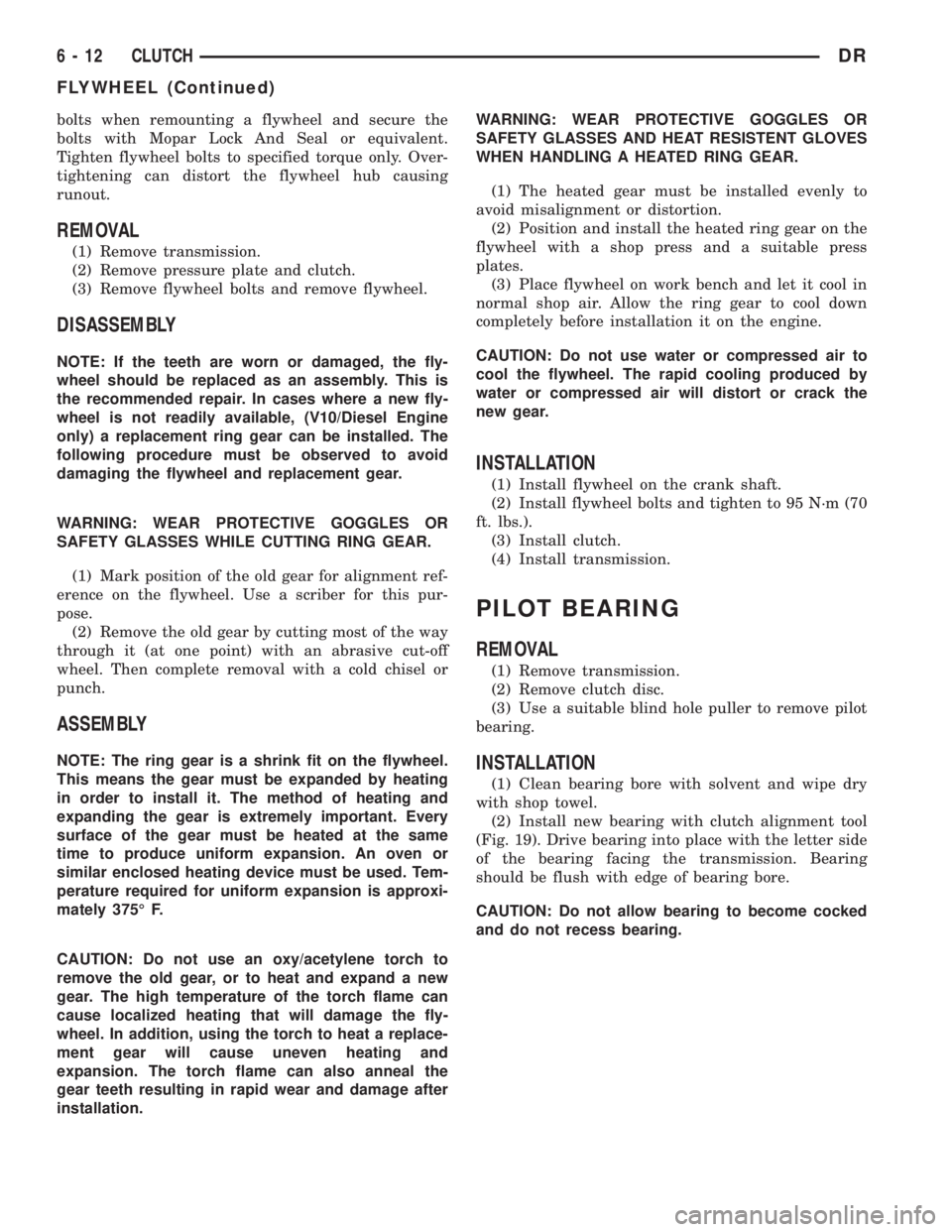
(2) Install new bearing with clutch alignment tool
(Fig. 19). Drive bearing into place with the letter side
of the bearing facing the transmission. Bearing
should be flush with edge of bearing bore.
CAUTION: Do not allow bearing to become cocked
and do not recess bearing.
6 - 12 CLUTCHDR
FLYWHEEL (Continued)
Page 286 of 2895
(3) Install clutch disc, pressure plate and trans-
mission.
LINKAGE
REMOVAL
CAUTION: The hydraulic linkage has a quick dis-
connect at the slave cylinder. This fitting should
never be disconnected or tampered with. Once the
hydraulic line is connected to the slave cylinder, it
should never be disconnected.
(1) Raise and support vehicle.
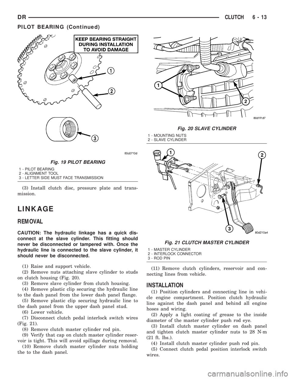
(2) Remove nuts attaching slave cylinder to studs
on clutch housing (Fig. 20).
(3) Remove slave cylinder from clutch housing.
(4) Remove plastic clip securing the hydraulic line
to the dash panel from the lower dash panel flange.
(5) Remove plastic clip securing hydraulic line to
the dash panel from the upper dash panel stud.
(6) Lower vehicle.
(7) Disconnect clutch pedal interlock switch wires
(Fig. 21).
(8) Remove clutch master cylinder rod pin.
(9) Verify that cap on clutch master cylinder reser-
voir is tight. This will avoid spillage during removal.
(10) Remove clutch master cylinder nuts holding
the to the dash panel.(11) Remove clutch cylinders, reservoir and con-
necting lines from vehicle.
INSTALLATION
(1) Position cylinders and connecting line in vehi-
cle engine compartment. Position clutch hydraulic
line against the dash panel and behind all engine
hoses and wiring.
(2) Apply a light coating of grease to the inside
diameter of the master cylinder push rod eye.
(3) Install clutch master cylinder on dash panel
and tighten clutch master cylinder nuts to 28 N´m
(21 ft. lbs.).
(4) Install clutch master cylinder push rod pin.
(5) Connect clutch pedal position interlock switch
wires.
Fig. 19 PILOT BEARING
1 - PILOT BEARING
2 - ALIGNMENT TOOL
3 - LETTER SIDE MUST FACE TRANSMISSION
Fig. 20 SLAVE CYLINDER
1 - MOUNTING NUTS
2 - SLAVE CYLINDER
Fig. 21 CLUTCH MASTER CYLINDER
1 - MASTER CYLINDER
2 - INTERLOCK CONNECTOR
3 - ROD PIN
DRCLUTCH 6 - 13
PILOT BEARING (Continued)
Page 287 of 2895
(6) Install plastic clip securing hydraulic line to
the dash panel into the lower dash panel flange.
(7) Install plastic clip securing hydraulic line to
the dash panel onto the upper dash panel stud.
(8) Raise vehicle.
(9) Install slave cylinder and verify cylinder rod is
properly seated in release lever.
(10) Install and tighten slave cylinder nuts to 23
N´m (17 ft. lbs.).
(11) Ifnewclutch linkage is being installed, con-
nect the clutch hydraulic line to the clutch slave cyl-
inder.
CAUTION: Once the clutch hydraulic line is con-
nected to the slave cylinder, it should never be dis-
connected.
(12) Lower vehicle.
(13) Operate linkage several times to verify proper
operation.
CLUTCH PEDAL POSITION
SWITCH
DESCRIPTION
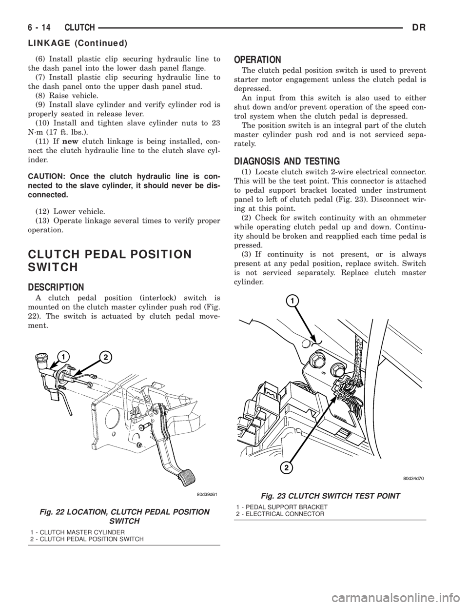
A clutch pedal position (interlock) switch is
mounted on the clutch master cylinder push rod (Fig.
22). The switch is actuated by clutch pedal move-
ment.
OPERATION
The clutch pedal position switch is used to prevent
starter motor engagement unless the clutch pedal is
depressed.
An input from this switch is also used to either
shut down and/or prevent operation of the speed con-
trol system when the clutch pedal is depressed.
The position switch is an integral part of the clutch
master cylinder push rod and is not serviced sepa-
rately.
DIAGNOSIS AND TESTING
(1) Locate clutch switch 2-wire electrical connector.
This will be the test point. This connector is attached
to pedal support bracket located under instrument
panel to left of clutch pedal (Fig. 23). Disconnect wir-
ing at this point.
(2) Check for switch continuity with an ohmmeter
while operating clutch pedal up and down. Continu-
ity should be broken and reapplied each time pedal is
pressed.
(3) If continuity is not present, or is always
present at any pedal position, replace switch. Switch
is not serviced separately. Replace clutch master
cylinder.
Fig. 22 LOCATION, CLUTCH PEDAL POSITION
SWITCH
1 - CLUTCH MASTER CYLINDER
2 - CLUTCH PEDAL POSITION SWITCH
Fig. 23 CLUTCH SWITCH TEST POINT
1 - PEDAL SUPPORT BRACKET
2 - ELECTRICAL CONNECTOR
6 - 14 CLUTCHDR
LINKAGE (Continued)
Page 288 of 2895
COOLING
TABLE OF CONTENTS
page page
COOLING
DESCRIPTION
DESCRIPTION - COOLING SYSTEM FLOW
3.7L/4.7L ENGINE......................1
DESCRIPTION - COOLING SYSTEM FLOW -
5.9L ENGINE..........................1
DESCRIPTIONÐCOOLING SYSTEM FLOW -
5.9L DIESEL..........................2
DESCRIPTION - HOSE CLAMPS...........3
OPERATION
OPERATIONÐCOOLING SYSTEM.........3
OPERATIONÐHOSE CLAMPS............5
DIAGNOSIS AND TESTING
DIAGNOSIS AND TESTINGÐON-BOARD
DIAGNOSTICS (OBD)...................5
DIAGNOSIS AND TESTINGÐCOOLING
SYSTEM - TESTING FOR LEAKS..........5
DIAGNOSIS AND TESTING - COOLING
SYSTEM DIESEL ENGINE................7
DIAGNOSIS AND TESTING - PRELIMINARY
CHECKS............................10
STANDARD PROCEDURE
STANDARD PROCEDURE - COOLANT
LEVEL CHECK........................17STANDARD PROCEDURE - COOLING
SYSTEM CLEANING/REVERSE FLUSHING . . 17
STANDARD PROCEDUREÐDRAINING
COOLING SYSTEM 3.7L/4.7L/5.7L ENGINE . . 18
STANDARD PROCEDURE - REFILLING
COOLING SYSTEM 3.7L/4.7L/5.7L ENGINE . . 18
STANDARD PROCEDUREÐDRAINING
COOLING SYSTEM 5.9L/8.0L ENGINE......18
STANDARD PROCEDUREÐREFILLING
COOLING SYSTEM 5.9L/8.0L ENGINE......18
STANDARD PROCEDUREÐDRAINING
COOLING SYSTEM 5.9L DIESEL ENGINE . . . 19
STANDARD PROCEDUREÐREFILLING
COOLING SYSTEM 5.9L DIESEL ENGINE . . . 19
STANDARD PROCEDURE - ADDING
ADDITIONAL COOLANT.................19
SPECIFICATIONS
TORQUE............................20
SPECIFICATIONS -....................20
SPECIAL TOOLS
COOLING...........................20
ACCESSORY DRIVE......................22
ENGINE...............................35
TRANSMISSION.........................72
COOLING
DESCRIPTION
DESCRIPTION - COOLING SYSTEM FLOW
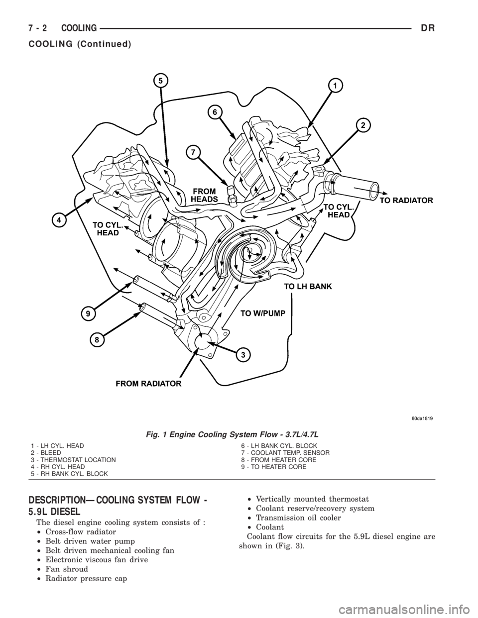
3.7L/4.7L ENGINE
The cooling system regulates engine operating tem-
perature. It allows the engine to reach normal oper-
ating temperature as quickly as possible. It also
maintains normal operating temperature and pre-
vents overheating.
The cooling system provides a means of heating
the passenger compartment and cooling the auto-
matic transmission fluid (if equipped). The cooling
system is pressurized and uses a centrifugal water
pump to circulate coolant through the system and a
coolant deaeration and reserve system that utilizes a
pressurized degas bottle (hot bottle).
An optional factory installed maximum duty cool-
ing package is available on most models. This pack-
age will provide additional cooling capacity forvehicles used under extreme conditions such as
trailer towing in high ambient temperatures (Fig. 1).
DESCRIPTION - COOLING SYSTEM FLOW -
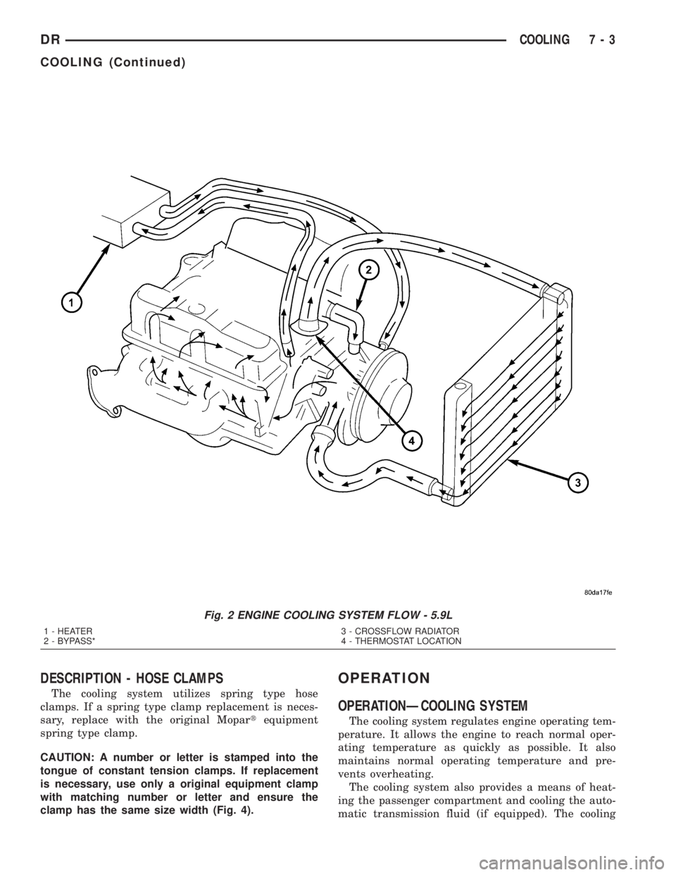
5.9L ENGINE
The cooling system regulates engine operating tem-
perature. It allows the engine to reach normal oper-
ating temperature as quickly as possible. It also
maintains normal operating temperature and pre-
vents overheating.
The cooling system also provides a means of heat-
ing the passenger compartment and cooling the auto-
matic transmission fluid (if equipped). The cooling
system uses a coolant recovery / reserve system that
utilizes an ambient overflow bottle.
An optional factory installed maximum duty cool-
ing package is available on most models. This pack-
age will provide additional cooling capacity for
vehicles used under extreme conditions such as
trailer towing in high ambient temperatures (Fig. 2).
DRCOOLING 7 - 1
Page 289 of 2895
DESCRIPTIONÐCOOLING SYSTEM FLOW -
5.9L DIESEL
The diesel engine cooling system consists of :
²Cross-flow radiator
²Belt driven water pump
²Belt driven mechanical cooling fan
²Electronic viscous fan drive
²Fan shroud
²Radiator pressure cap²Vertically mounted thermostat
²Coolant reserve/recovery system
²Transmission oil cooler
²Coolant
Coolant flow circuits for the 5.9L diesel engine are
shown in (Fig. 3).
Fig. 1 Engine Cooling System Flow - 3.7L/4.7L
1 - LH CYL. HEAD
2 - BLEED
3 - THERMOSTAT LOCATION
4 - RH CYL. HEAD
5 - RH BANK CYL. BLOCK6 - LH BANK CYL. BLOCK
7 - COOLANT TEMP. SENSOR
8 - FROM HEATER CORE
9 - TO HEATER CORE
7 - 2 COOLINGDR
COOLING (Continued)
Page 290 of 2895
DESCRIPTION - HOSE CLAMPS
The cooling system utilizes spring type hose
clamps. If a spring type clamp replacement is neces-
sary, replace with the original Mopartequipment
spring type clamp.
CAUTION: A number or letter is stamped into the
tongue of constant tension clamps. If replacement
is necessary, use only a original equipment clamp
with matching number or letter and ensure the
clamp has the same size width (Fig. 4).
OPERATION
OPERATIONÐCOOLING SYSTEM
The cooling system regulates engine operating tem-
perature. It allows the engine to reach normal oper-
ating temperature as quickly as possible. It also
maintains normal operating temperature and pre-
vents overheating.
The cooling system also provides a means of heat-
ing the passenger compartment and cooling the auto-
matic transmission fluid (if equipped). The cooling
Fig. 2 ENGINE COOLING SYSTEM FLOW - 5.9L
1 - HEATER
2 - BYPASS*3 - CROSSFLOW RADIATOR
4 - THERMOSTAT LOCATION
DRCOOLING 7 - 3
COOLING (Continued)