Power Systems DODGE RAM 2003 Service Owner's Manual
[x] Cancel search | Manufacturer: DODGE, Model Year: 2003, Model line: RAM, Model: DODGE RAM 2003Pages: 2895, PDF Size: 83.15 MB
Page 1240 of 2895
8W-97 POWER DISTRIBUTION
TABLE OF CONTENTS
page page
POWER DISTRIBUTION
DESCRIPTION..........................1
OPERATION............................1
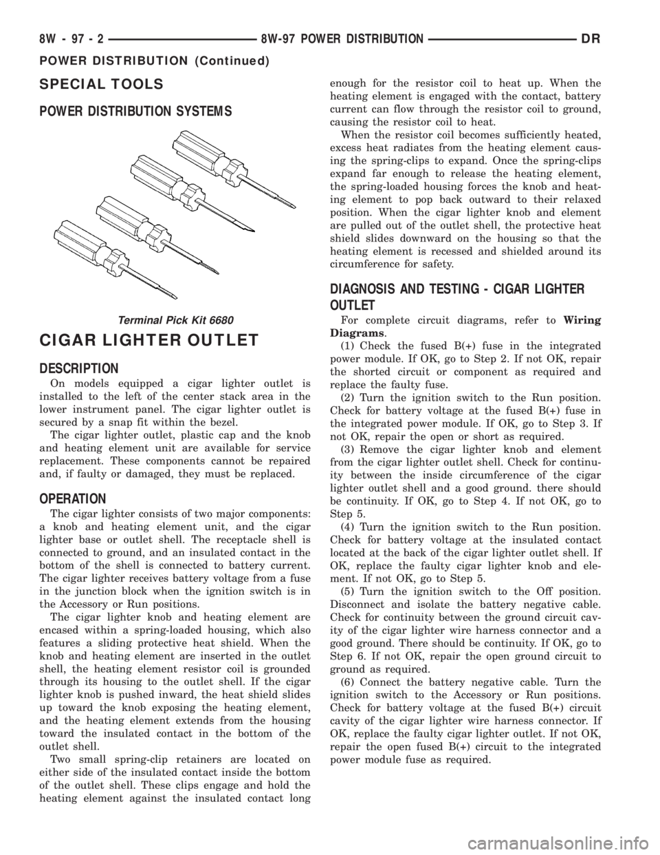
SPECIAL TOOLS
POWER DISTRIBUTION SYSTEMS.........2
CIGAR LIGHTER OUTLET
DESCRIPTION..........................2
OPERATION............................2
DIAGNOSIS AND TESTING - CIGAR LIGHTER
OUTLET.............................2
INTEGRATED POWER MODULE
DESCRIPTION..........................3
OPERATION............................3
REMOVAL.............................3
INSTALLATION..........................4
FRONT CONTROL MODULE
DESCRIPTION..........................4
OPERATION............................5
DIAGNOSIS AND TESTING - FRONT
CONTROL MODULE....................5
REMOVAL.............................5
INSTALLATION..........................5
IOD FUSE
DESCRIPTION..........................6OPERATION............................6
REMOVAL.............................6
INSTALLATION..........................7
POWER OUTLET
DESCRIPTION..........................7
OPERATION............................7
DIAGNOSIS AND TESTING - POWER OUTLET . 7
REMOVAL.............................7
INSTALLATION..........................7
RELAY
DESCRIPTION..........................8
OPERATION............................8
DIAGNOSIS AND TESTING - RELAY.........8
REMOVAL.............................9
INSTALLATION..........................9
MICRO RELAY
DESCRIPTION..........................9
OPERATION............................9
DIAGNOSIS AND TESTING - MICRO-RELAY . . . 9
REMOVAL.............................10
INSTALLATION.........................10
POWER DISTRIBUTION
DESCRIPTION
This group covers the various standard and
optional power distribution components used on this
model. The power distribution system for this vehicle
consists of the following components:
²Integrated Power Module (IPM)
²Front Control Module (FCM)
²Power Distribution Center (PDC)
²Power Outlets
²Cigar Lighter Outlets
²Relays
Refer to Wiring Diagrams for complete circuit sche-
matics.
The power distribution system also incorporates
various types of circuit control and protection fea-
tures, including:
²Automatic resetting circuit breakers
²Blade-type fuses
²Cartridge fuses
²RelaysFollowing are general descriptions of the major
components in the power distribution system. See the
owner's manual in the vehicle glove box for more
information on the features and use of all of the
power distribution system components.
OPERATION
The power distribution system for this vehicle is
designed to provide safe, reliable, and centralized dis-
tribution points for the electrical current required to
operate all of the many standard and optional facto-
ry-installed electrical and electronic powertrain,
chassis, safety, security, comfort and convenience sys-
tems. At the same time, the power distribution sys-
tem was designed to provide ready access to these
electrical distribution points for the vehicle techni-
cian to use when conducting diagnosis and repair of
faulty circuits. The power distribution system can
also prove useful for the sourcing of additional elec-
trical circuits that may be required to provide the
electrical current needed to operate many accessories
that the vehicle owner may choose to have installed
in the aftermarket.
DR8W-97 POWER DISTRIBUTION 8W - 97 - 1
Page 1241 of 2895
SPECIAL TOOLS
POWER DISTRIBUTION SYSTEMS
CIGAR LIGHTER OUTLET
DESCRIPTION
On models equipped a cigar lighter outlet is
installed to the left of the center stack area in the
lower instrument panel. The cigar lighter outlet is
secured by a snap fit within the bezel.
The cigar lighter outlet, plastic cap and the knob
and heating element unit are available for service
replacement. These components cannot be repaired
and, if faulty or damaged, they must be replaced.
OPERATION
The cigar lighter consists of two major components:
a knob and heating element unit, and the cigar
lighter base or outlet shell. The receptacle shell is
connected to ground, and an insulated contact in the
bottom of the shell is connected to battery current.
The cigar lighter receives battery voltage from a fuse
in the junction block when the ignition switch is in
the Accessory or Run positions.
The cigar lighter knob and heating element are
encased within a spring-loaded housing, which also
features a sliding protective heat shield. When the
knob and heating element are inserted in the outlet
shell, the heating element resistor coil is grounded
through its housing to the outlet shell. If the cigar
lighter knob is pushed inward, the heat shield slides
up toward the knob exposing the heating element,
and the heating element extends from the housing
toward the insulated contact in the bottom of the
outlet shell.
Two small spring-clip retainers are located on
either side of the insulated contact inside the bottom
of the outlet shell. These clips engage and hold the
heating element against the insulated contact longenough for the resistor coil to heat up. When the
heating element is engaged with the contact, battery
current can flow through the resistor coil to ground,
causing the resistor coil to heat.
When the resistor coil becomes sufficiently heated,
excess heat radiates from the heating element caus-
ing the spring-clips to expand. Once the spring-clips
expand far enough to release the heating element,
the spring-loaded housing forces the knob and heat-
ing element to pop back outward to their relaxed
position. When the cigar lighter knob and element
are pulled out of the outlet shell, the protective heat
shield slides downward on the housing so that the
heating element is recessed and shielded around its
circumference for safety.
DIAGNOSIS AND TESTING - CIGAR LIGHTER
OUTLET
For complete circuit diagrams, refer toWiring
Diagrams.
(1) Check the fused B(+) fuse in the integrated
power module. If OK, go to Step 2. If not OK, repair
the shorted circuit or component as required and
replace the faulty fuse.
(2) Turn the ignition switch to the Run position.
Check for battery voltage at the fused B(+) fuse in
the integrated power module. If OK, go to Step 3. If
not OK, repair the open or short as required.
(3) Remove the cigar lighter knob and element
from the cigar lighter outlet shell. Check for continu-
ity between the inside circumference of the cigar
lighter outlet shell and a good ground. there should
be continuity. If OK, go to Step 4. If not OK, go to
Step 5.
(4) Turn the ignition switch to the Run position.
Check for battery voltage at the insulated contact
located at the back of the cigar lighter outlet shell. If
OK, replace the faulty cigar lighter knob and ele-
ment. If not OK, go to Step 5.
(5) Turn the ignition switch to the Off position.
Disconnect and isolate the battery negative cable.
Check for continuity between the ground circuit cav-
ity of the cigar lighter wire harness connector and a
good ground. There should be continuity. If OK, go to
Step 6. If not OK, repair the open ground circuit to
ground as required.
(6) Connect the battery negative cable. Turn the
ignition switch to the Accessory or Run positions.
Check for battery voltage at the fused B(+) circuit
cavity of the cigar lighter wire harness connector. If
OK, replace the faulty cigar lighter outlet. If not OK,
repair the open fused B(+) circuit to the integrated
power module fuse as required.Terminal Pick Kit 6680
8W - 97 - 2 8W-97 POWER DISTRIBUTIONDR
POWER DISTRIBUTION (Continued)
Page 1244 of 2895
tery and provides the primary means of circuit pro-
tection and power distribution for all vehicle
electrical systems. The front control module controls
power to some of these vehicle systems electrical and
electromechanical loads based on inputs received
from hard wired switch inputs and data received on
the PCI bus circuit (J1850).
For information on theIntegrated Power Mod-
ule Refer to the Power Distribution Sectionof
the service manual.
OPERATION
As messages are sent over the PCI bus circuit, the
front control module reads these messages and con-
trols power to some of the vehicles electrical systems
by completing the circuit to ground (low side driver)
or completing the circuit to 12 volt power (high side
driver). The following functions areControlledby
the Front Control Module:
²Headlamp Power with Voltage Regulation
²Windshield Wiper ªON/OFFº Relay Actuation
²Windshield Wiper ªHI/LOº Relay Actuation
²Windshield Washer Pump Motor
²Fog Lamp Relay Actuation
²Park Lamp Relay Actuation
²Horn Relay Actuation
The following inputs areReceived/Monitoredby
the Front Control Module:
²B+ Connection Detection²Power Ground
²Ambient Temperature Sensing
²Ignition Switch Run
²Washer Fluid Level Switch
²Windshield Wiper Park Switch
²PCI Bus Circuit
DIAGNOSIS AND TESTING - FRONT CONTROL
MODULE
The front control module is a printed circuit board
based module with a on-board micro-processor. The
front control module interfaces with other electronic
modules in the vehicle via the Programmable Com-
munications Interface (PCI) data bus (J1850). In
order to obtain conclusive testing the Programmable
Communications Interface (PCI) data bus network
and all of the electronic modules that provide inputs
to, or receive outputs from the front control module
must be checked. All PCI (J1850) communication
faults must be resolved prior to further diagnosing
any front control module related issues.
The front control module was designed to be diag-
nosed with an appropriate diagnostic scan tool, such
as the DRB IIIt. The most reliable, efficient, and
accurate means to diagnose the front control module
requires the use of a DRB IIItscan tool and the
proper Body Diagnostic Procedures manual.
Before any testing of the front control module is
attempted, the battery should be fully charged and
all wire harness and ground connections inspected
around the affected areas on the vehicle.
REMOVAL
(1) Disconnect the positive and negative battery
cables from the battery.
(2) Partially remove the integrated power module
from the engine compartment (Refer to 8 - ELECTRI-
CAL/POWER DISTRIBUTION/INTEGRATED
POWER MODULE - REMOVAL).
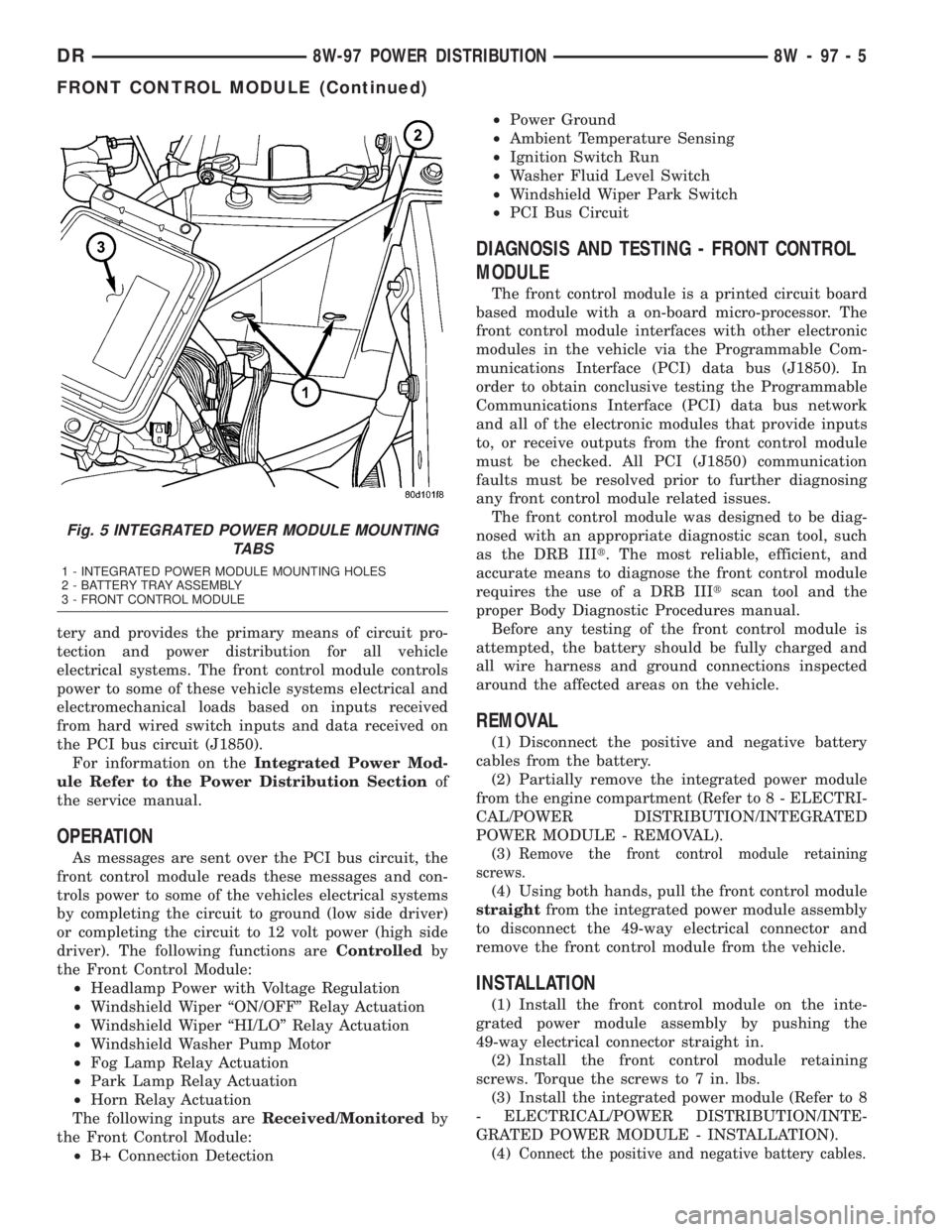
(3)
Remove the front control module retaining
screws.
(4) Using both hands, pull the front control module
straightfrom the integrated power module assembly
to disconnect the 49-way electrical connector and
remove the front control module from the vehicle.
INSTALLATION
(1) Install the front control module on the inte-
grated power module assembly by pushing the
49-way electrical connector straight in.
(2) Install the front control module retaining
screws. Torque the screws to 7 in. lbs.
(3) Install the integrated power module (Refer to 8
- ELECTRICAL/POWER DISTRIBUTION/INTE-
GRATED POWER MODULE - INSTALLATION).
(4)
Connect the positive and negative battery cables.
Fig. 5 INTEGRATED POWER MODULE MOUNTING
TABS
1 - INTEGRATED POWER MODULE MOUNTING HOLES
2 - BATTERY TRAY ASSEMBLY
3 - FRONT CONTROL MODULE
DR8W-97 POWER DISTRIBUTION 8W - 97 - 5
FRONT CONTROL MODULE (Continued)
Page 1666 of 2895
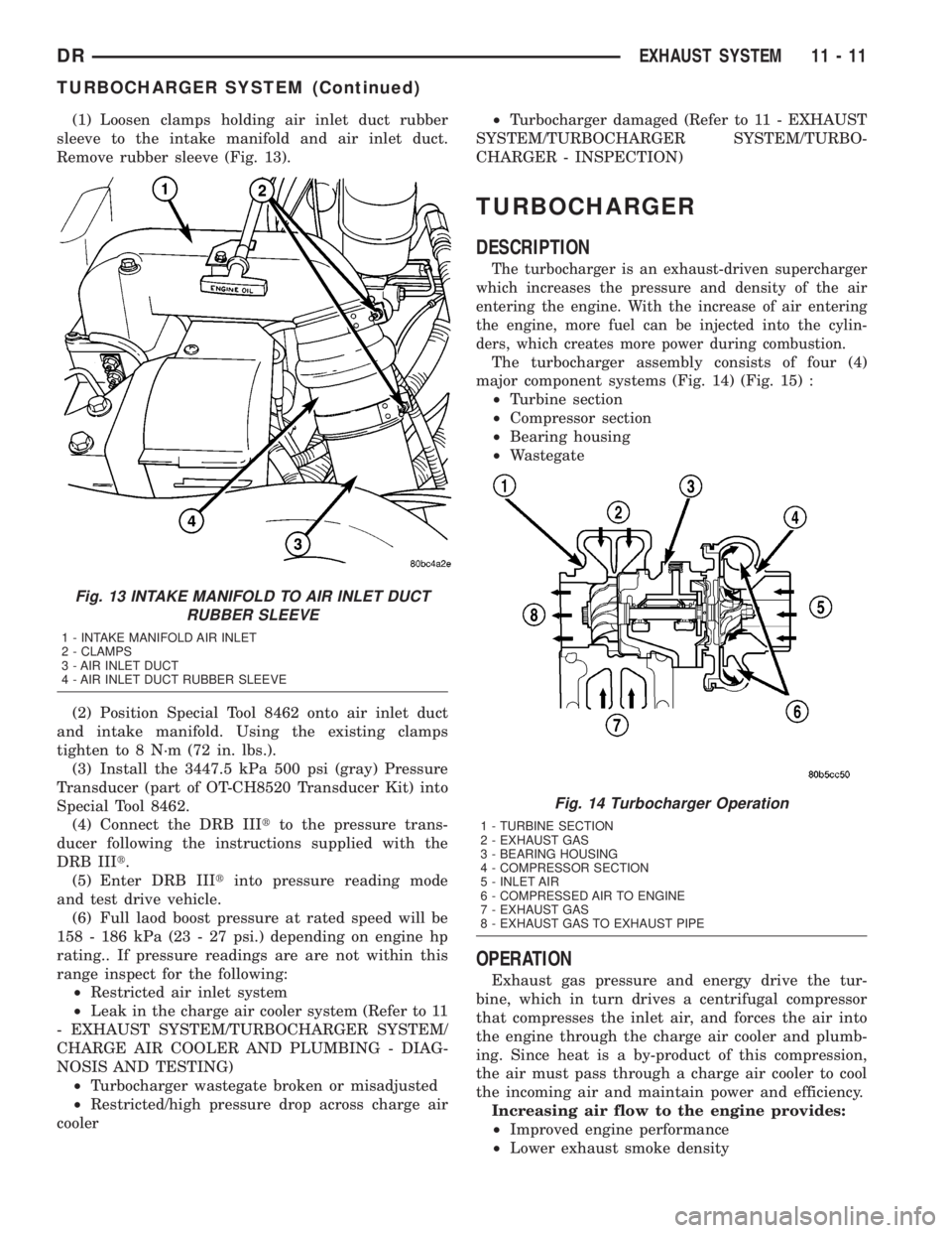
(1) Loosen clamps holding air inlet duct rubber
sleeve to the intake manifold and air inlet duct.
Remove rubber sleeve (Fig. 13).
(2) Position Special Tool 8462 onto air inlet duct
and intake manifold. Using the existing clamps
tighten to 8 N´m (72 in. lbs.).
(3) Install the 3447.5 kPa 500 psi (gray) Pressure
Transducer (part of OT-CH8520 Transducer Kit) into
Special Tool 8462.
(4) Connect the DRB IIItto the pressure trans-
ducer following the instructions supplied with the
DRB IIIt.
(5) Enter DRB IIItinto pressure reading mode
and test drive vehicle.
(6) Full laod boost pressure at rated speed will be
158 - 186 kPa (23 - 27 psi.) depending on engine hp
rating.. If pressure readings are are not within this
range inspect for the following:
²Restricted air inlet system
²Leak in the charge air cooler system (Refer to 11
- EXHAUST SYSTEM/TURBOCHARGER SYSTEM/
CHARGE AIR COOLER AND PLUMBING - DIAG-
NOSIS AND TESTING)
²Turbocharger wastegate broken or misadjusted
²Restricted/high pressure drop across charge air
cooler²Turbocharger damaged (Refer to 11 - EXHAUST
SYSTEM/TURBOCHARGER SYSTEM/TURBO-
CHARGER - INSPECTION)
TURBOCHARGER
DESCRIPTION
The turbocharger is an exhaust-driven supercharger
which increases the pressure and density of the air
entering the engine. With the increase of air entering
the engine, more fuel can be injected into the cylin-
ders, which creates more power during combustion.
The turbocharger assembly consists of four (4)
major component systems (Fig. 14) (Fig. 15) :
²Turbine section
²Compressor section
²Bearing housing
²Wastegate
OPERATION
Exhaust gas pressure and energy drive the tur-
bine, which in turn drives a centrifugal compressor
that compresses the inlet air, and forces the air into
the engine through the charge air cooler and plumb-
ing. Since heat is a by-product of this compression,
the air must pass through a charge air cooler to cool
the incoming air and maintain power and efficiency.
Increasing air flow to the engine provides:
²Improved engine performance
²Lower exhaust smoke density
Fig. 13 INTAKE MANIFOLD TO AIR INLET DUCT
RUBBER SLEEVE
1 - INTAKE MANIFOLD AIR INLET
2 - CLAMPS
3 - AIR INLET DUCT
4 - AIR INLET DUCT RUBBER SLEEVE
Fig. 14 Turbocharger Operation
1 - TURBINE SECTION
2 - EXHAUST GAS
3 - BEARING HOUSING
4 - COMPRESSOR SECTION
5 - INLET AIR
6 - COMPRESSED AIR TO ENGINE
7 - EXHAUST GAS
8 - EXHAUST GAS TO EXHAUST PIPE
DREXHAUST SYSTEM 11 - 11
TURBOCHARGER SYSTEM (Continued)
Page 1794 of 2895
STEERING
TABLE OF CONTENTS
page page
STEERING
DESCRIPTION..........................1
OPERATION............................1
DIAGNOSIS AND TESTING
DIAGNOSIS AND TESTING - POWER
STEERING SYSTEM....................2
DIAGNOSIS AND TESTING - POWER
STEERING FLOW AND PRESSURE........4
SPECIAL TOOLS
STEERING...........................5COLUMN...............................6
GEAR - INDEPENDENT FRONT SUSPENSION..16
GEAR - LINK/COIL.......................19
LINKAGE - INDEPENDENT FRONT
SUSPENSION...........................31
LINKAGE - LINK/COIL....................33
PUMP.................................38
STEERING
DESCRIPTION
CAUTION: MOPARTATF+4 is to be used in the
power steering system. No other power steering or
automatic transmission fluid is to be used in the
system. Damage may result to the power steering
pump and system if any other fluid is used, and do
not overfill.
Power steering systems consist of:
²Steering column
²Rack and pinion steering gear
²Belt driven hydraulic steering pump
²Pump pressure and return hoses
²Oil Cooler
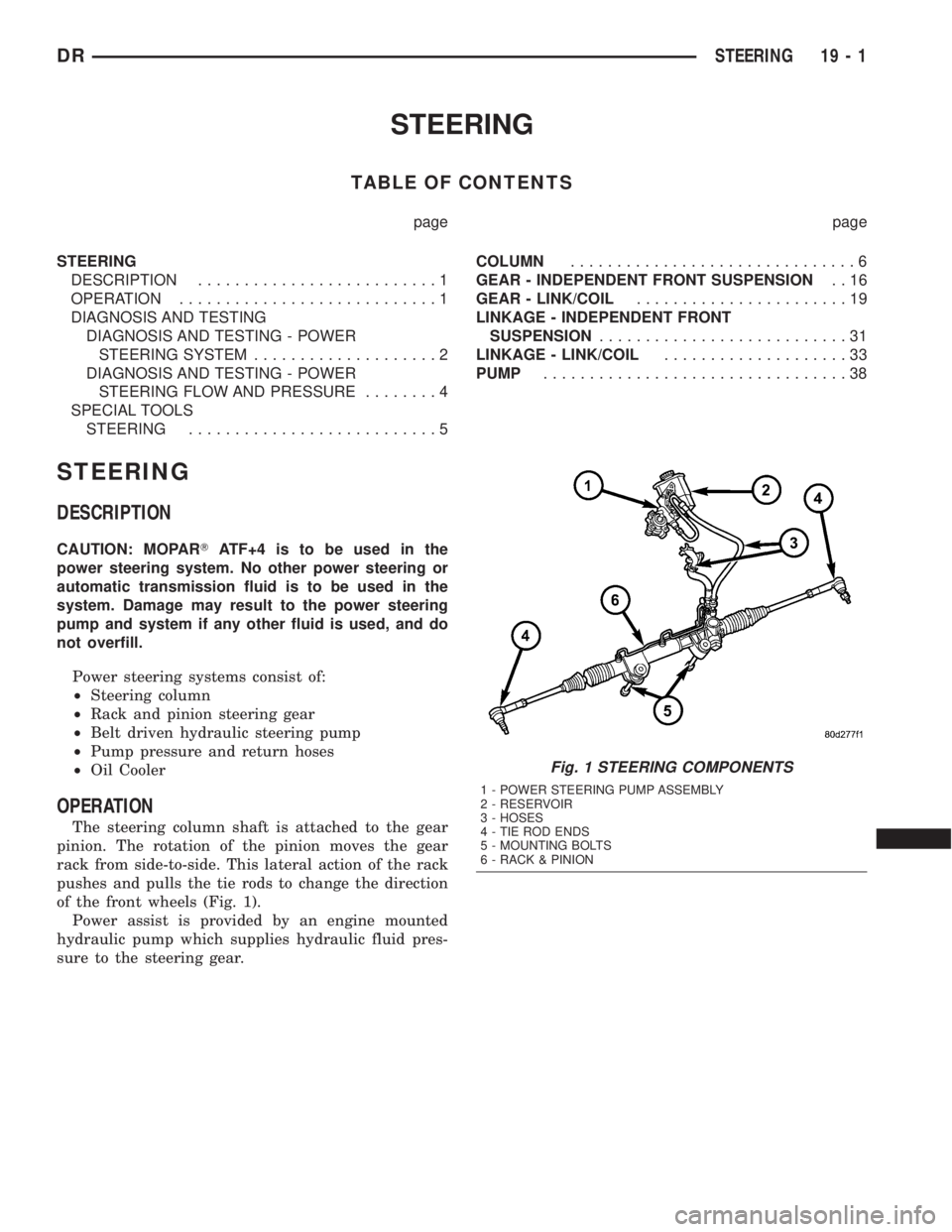
OPERATION
The steering column shaft is attached to the gear
pinion. The rotation of the pinion moves the gear
rack from side-to-side. This lateral action of the rack
pushes and pulls the tie rods to change the direction
of the front wheels (Fig. 1).
Power assist is provided by an engine mounted
hydraulic pump which supplies hydraulic fluid pres-
sure to the steering gear.
Fig. 1 STEERING COMPONENTS
1 - POWER STEERING PUMP ASSEMBLY
2 - RESERVOIR
3 - HOSES
4 - TIE ROD ENDS
5 - MOUNTING BOLTS
6 - RACK & PINION
DRSTEERING 19 - 1
Page 1795 of 2895
DIAGNOSIS AND TESTING
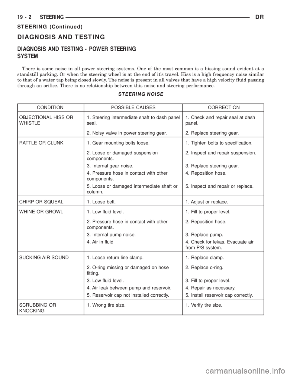
DIAGNOSIS AND TESTING - POWER STEERING
SYSTEM
There is some noise in all power steering systems. One of the most common is a hissing sound evident at a
standstill parking. Or when the steering wheel is at the end of it's travel. Hiss is a high frequency noise similar
to that of a water tap being closed slowly. The noise is present in all valves that have a high velocity fluid passing
through an orifice. There is no relationship between this noise and steering performance.
STEERING NOISE
CONDITION POSSIBLE CAUSES CORRECTION
OBJECTIONAL HISS OR
WHISTLE1. Steering intermediate shaft to dash panel
seal.1. Check and repair seal at dash
panel.
2. Noisy valve in power steering gear. 2. Replace steering gear.
RATTLE OR CLUNK 1. Gear mounting bolts loose. 1. Tighten bolts to specification.
2. Loose or damaged suspension
components.2. Inspect and repair suspension.
3. Internal gear noise. 3. Replace steering gear.
4. Pressure hose in contact with other
components.4. Reposition hose.
5. Loose or damaged intermediate shaft or
column.5. Inspect and repair or replace.
CHIRP OR SQUEAL 1. Loose belt. 1. Adjust or replace.
WHINE OR GROWL 1. Low fluid level. 1. Fill to proper level.
2. Pressure hose in contact with other
components.2. Reposition hose.
3. Internal pump noise. 3. Replace pump.
4. Air in fluid 4. Check for lekas, Evacuate air
from P/S system.
SUCKING AIR SOUND 1. Loose return line clamp. 1. Replace clamp.
2. O-ring missing or damaged on hose
fitting.2. Replace o-ring.
3. Low fluid level. 3. Fill to proper level.
4. Air leak between pump and reservoir. 4. Repair as necessary.
5. Reservoir cap not installed correctly. 5. Install reservoir cap correctly.
SCRUBBING OR
KNOCKING1. Wrong tire size. 1. Verify tire size.
19 - 2 STEERINGDR
STEERING (Continued)
Page 2800 of 2895
(1) Recover refrigerant(Refer to 24 - HEATING &
AIR CONDITIONING/PLUMBING - STANDARD
PROCEDURE).
(2) Remove and disassemble the HVAC housing.
(Refer to 24 - HEATING & AIR CONDITIONING/
DISTRIBUTION/HVAC HOUSING - REMOVAL)
(Refer to 24 - HEATING & AIR CONDITIONING/
DISTRIBUTION/HVAC HOUSING - DISASSEMBLY)
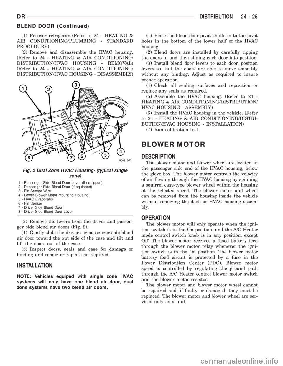
(3) Remove the levers from the driver and passen-
ger side blend air doors (Fig. 2).
(4) Gently slide the drivers or passenger side blend
air door toward the out side of the case and tilt and
lift the doors out of the case.
(5) Inspect doors, seals and case for damage or
binding and repair or replace as required.
INSTALLATION
NOTE: Vehicles equiped with single zone HVAC
systems will only have one blend air door, dual
zone systems have two blend air doors.(1) Place the blend door pivot shafts in to the pivot
holes in the bottom of the lower half of the HVAC
housing.
(2) Blend doors are installed by carefully tipping
the doors in and then sliding each door into position.
(3) Install blend door levers to each door, position
levers so that the doors are able to move smoothly
without any binding. Adjust as required to insure
proper operation.
(4) Check all sealing surfaces and reposition or
replace any seals as required.
(5) Assemble the HVAC housing. (Refer to 24 -
HEATING & AIR CONDITIONING/DISTRIBUTION/
HVAC HOUSING - ASSEMBLY)
(6) Install the HVAC housing in the vehicle. (Refer
to 24 - HEATING & AIR CONDITIONING/DISTRI-
BUTION/HVAC HOUSING - INSTALLATION)
(7) Run calibration test.
BLOWER MOTOR
DESCRIPTION
The blower motor and blower wheel are located in
the passenger side end of the HVAC housing, below
the glove box. The blower motor controls the velocity
of air flowing through the HVAC housing by spinning
a squirrel cage-type blower wheel within the housing
at the selected speed. The blower motor and wheel
can be removed from the housing inside the vehicle
without removing the dash or HVAC housing assem-
bly.
OPERATION
The blower motor will only operate when the igni-
tion switch is in the On position, and the A/C Heater
mode control switch knob is in any position, except
Off. The blower motor receives a fused battery feed
through the blower motor relay whenever the igni-
tion switch is in the On position. The blower motor
battery feed circuit is protected by a fuse in the
Power Distribution Center (PDC). Blower motor
speed is controlled by regulating the ground path
through the A/C Heater control blower motor switch
and the blower motor resistor.
The blower motor and blower motor wheel cannot
be repaired and, if faulty or damaged, they must be
replaced. The blower motor and blower wheel are ser-
viced only as a unit.
Fig. 2 Dual Zone HVAC Housing- (typical single
zone)
1 - Passenger Side Blend Door Lever (if equipped)
2 - Passenger Side Blend Door (if equipped)
3 - Fin Sensor Wire
4 - Lower Blower Motor Mounting Housing
5 - HVAC Evaporator
6 - Fin Sensor
7 - Driver Side Blend Door
8 - Driver Side Blend Door Lever
DRDISTRIBUTION 24 - 25
BLEND DOOR (Continued)
Page 2830 of 2895
EMISSIONS CONTROL
TABLE OF CONTENTS
page page
EMISSIONS CONTROL
DESCRIPTION
DESCRIPTION - STATE DISPLAY TEST
MODE...............................1
DESCRIPTION - CIRCUIT ACTUATION TEST
MODE...............................1
DESCRIPTION - DIAGNOSTIC TROUBLE
CODES..............................1
DESCRIPTION - TASK MANAGER..........1DESCRIPTION - MONITORED SYSTEMS....1
DESCRIPTION - TRIP DEFINITION.........4
DESCRIPTION - COMPONENT MONITORS . . 4
OPERATION
OPERATION..........................4
OPERATION - TASK MANAGER...........5
OPERATION - NON-MONITORED CIRCUITS . . 8
EVAPORATIVE EMISSIONS................10
EMISSIONS CONTROL
DESCRIPTION
DESCRIPTION - STATE DISPLAY TEST MODE
The switch inputs to the Powertrain Control Mod-
ule (PCM) have two recognized states; HIGH and
LOW. For this reason, the PCM cannot recognize the
difference between a selected switch position versus
an open circuit, a short circuit, or a defective switch.
If the State Display screen shows the change from
HIGH to LOW or LOW to HIGH, assume the entire
switch circuit to the PCM functions properly. Connect
the DRB scan tool to the data link connector and
access the state display screen. Then access either
State Display Inputs and Outputs or State Display
Sensors.
DESCRIPTION - CIRCUIT ACTUATION TEST
MODE
The Circuit Actuation Test Mode checks for proper
operation of output circuits or devices the Powertrain
Control Module (PCM) may not internally recognize.
The PCM attempts to activate these outputs and
allow an observer to verify proper operation. Most of
the tests provide an audible or visual indication of
device operation (click of relay contacts, fuel spray,
etc.). Except for intermittent conditions, if a device
functions properly during testing, assume the device,
its associated wiring, and driver circuit work cor-
rectly. Connect the DRB scan tool to the data link
connector and access the Actuators screen.
DESCRIPTION - DIAGNOSTIC TROUBLE CODES
A Diagnostic Trouble Code (DTC) indicates the
PCM has recognized an abnormal condition in the
system.Remember that DTC's are the results of a sys-
tem or circuit failure, but do not directly iden-
tify the failed component or components.
BULB CHECK
Each time the ignition key is turned to the ON
position, the malfunction indicator (check engine)
lamp on the instrument panel should illuminate for
approximately 2 seconds then go out. This is done for
a bulb check.
OBTAINING DTC'S USING DRB SCAN TOOL
(1) Obtain the applicable Powertrain Diagnostic
Manual.
(2) Obtain the DRB Scan Tool.
(3) Connect the DRB Scan Tool to the data link
(diagnostic) connector. This connector is located in
the passenger compartment; at the lower edge of
instrument panel; near the steering column.
(4) Turn the ignition switch on and access the
ªRead Faultº screen.
(5) Record all the DTC's and ªfreeze frameº infor-
mation shown on the DRB scan tool.
(6) To erase DTC's, use the ªErase Trouble Codeº
data screen on the DRB scan tool.Do not erase any
DTC's until problems have been investigated
and repairs have been performed.
DESCRIPTION - TASK MANAGER
The PCM is responsible for efficiently coordinating
the operation of all the emissions-related compo-
nents. The PCM is also responsible for determining if
the diagnostic systems are operating properly. The
software designed to carry out these responsibilities
is call the 'Task Manager'.
DESCRIPTION - MONITORED SYSTEMS
There are new electronic circuit monitors that
check fuel, emission, engine and ignition perfor-
DREMISSIONS CONTROL 25 - 1
Page 2831 of 2895
mance. These monitors use information from various
sensor circuits to indicate the overall operation of the
fuel, engine, ignition and emission systems and thus
the emissions performance of the vehicle.
The fuel, engine, ignition and emission systems
monitors do not indicate a specific component prob-
lem. They do indicate that there is an implied prob-
lem within one of the systems and that a specific
problem must be diagnosed.
If any of these monitors detect a problem affecting
vehicle emissions, the Malfunction Indicator Lamp
(MIL) will be illuminated. These monitors generate
Diagnostic Trouble Codes that can be displayed with
the MIL or a scan tool.
The following is a list of the system monitors:
²Misfire Monitor
²Fuel System Monitor
²Oxygen Sensor Monitor
²Oxygen Sensor Heater Monitor
²Catalyst Monitor
²Leak Detection Pump Monitor (if equipped)
All these system monitors require two consecutive
trips with the malfunction present to set a fault.
Refer to the appropriate Powertrain Diagnos-
tics Procedures manual for diagnostic proce-
dures.
The following is an operation and description of
each system monitor :
OXYGEN SENSOR (O2S) MONITOR
Effective control of exhaust emissions is achieved
by an oxygen feedback system. The most important
element of the feedback system is the O2S. The O2S
is located in the exhaust path. Once it reaches oper-
ating temperature 300É to 350ÉC (572É to 662ÉF), the
sensor generates a voltage that is inversely propor-
tional to the amount of oxygen in the exhaust. The
information obtained by the sensor is used to calcu-
late the fuel injector pulse width. This maintains a
14.7 to 1 Air Fuel (A/F) ratio. At this mixture ratio,
the catalyst works best to remove hydrocarbons (HC),
carbon monoxide (CO) and nitrogen oxide (NOx) from
the exhaust.
The O2S is also the main sensing element for the
Catalyst and Fuel Monitors.
The O2S can fail in any or all of the following
manners:
²slow response rate
²reduced output voltage
²dynamic shift
²shorted or open circuits
Response rate is the time required for the sensor to
switch from lean to rich once it is exposed to a richer
than optimum A/F mixture or vice versa. As the sen-
sor starts malfunctioning, it could take longer todetect the changes in the oxygen content of the
exhaust gas.
The output voltage of the O2S ranges from 0 to 1
volt. A good sensor can easily generate any output
voltage in this range as it is exposed to different con-
centrations of oxygen. To detect a shift in the A/F
mixture (lean or rich), the output voltage has to
change beyond a threshold value. A malfunctioning
sensor could have difficulty changing beyond the
threshold value.
OXYGEN SENSOR HEATER MONITOR
If there is an oxygen sensor (O2S) shorted to volt-
age DTC, as well as a O2S heater DTC, the O2S
fault MUST be repaired first. Before checking the
O2S fault, verify that the heater circuit is operating
correctly.
Effective control of exhaust emissions is achieved
by an oxygen feedback system. The most important
element of the feedback system is the O2S. The O2S
is located in the exhaust path. Once it reaches oper-
ating temperature 300É to 350ÉC (572 É to 662ÉF), the
sensor generates a voltage that is inversely propor-
tional to the amount of oxygen in the exhaust. The
information obtained by the sensor is used to calcu-
late the fuel injector pulse width. This maintains a
14.7 to 1 Air Fuel (A/F) ratio. At this mixture ratio,
the catalyst works best to remove hydrocarbons (HC),
carbon monoxide (CO) and nitrogen oxide (NOx) from
the exhaust.
The voltage readings taken from the O2S sensor
are very temperature sensitive. The readings are not
accurate below 300ÉC. Heating of the O2S sensor is
done to allow the engine controller to shift to closed
loop control as soon as possible. The heating element
used to heat the O2S sensor must be tested to ensure
that it is heating the sensor properly.
The O2S sensor circuit is monitored for a drop in
voltage. The sensor output is used to test the heater
by isolating the effect of the heater element on the
O2S sensor output voltage from the other effects.
LEAK DETECTION PUMP MONITOR (IF EQUIPPED)
The leak detection assembly incorporates two pri-
mary functions: it must detect a leak in the evapora-
tive system and seal the evaporative system so the
leak detection test can be run.
The primary components within the assembly are:
A three port solenoid that activates both of the func-
tions listed above; a pump which contains a switch,
two check valves and a spring/diaphragm, a canister
vent valve (CVV) seal which contains a spring loaded
vent seal valve.
Immediately after a cold start, between predeter-
mined temperature thresholds limits, the three port
solenoid is briefly energized. This initializes the
25 - 2 EMISSIONS CONTROLDR
EMISSIONS CONTROL (Continued)
Page 2833 of 2895
verter. The PCM calculates the A/F mixture from the
output of the O2S. A low voltage indicates high oxy-
gen content (lean mixture). A high voltage indicates a
low content of oxygen (rich mixture).
When the upstream O2S detects a lean condition,
there is an abundance of oxygen in the exhaust gas.
A functioning converter would store this oxygen so it
can use it for the oxidation of HC and CO. As the
converter absorbs the oxygen, there will be a lack of
oxygen downstream of the converter. The output of
the downstream O2S will indicate limited activity in
this condition.
As the converter loses the ability to store oxygen,
the condition can be detected from the behavior of
the downstream O2S. When the efficiency drops, no
chemical reaction takes place. This means the con-
centration of oxygen will be the same downstream as
upstream. The output voltage of the downstream
O2S copies the voltage of the upstream sensor. The
only difference is a time lag (seen by the PCM)
between the switching of the O2S's.
To monitor the system, the number of lean-to-rich
switches of upstream and downstream O2S's is
counted. The ratio of downstream switches to
upstream switches is used to determine whether the
catalyst is operating properly. An effective catalyst
will have fewer downstream switches than it has
upstream switches i.e., a ratio closer to zero. For a
totally ineffective catalyst, this ratio will be one-to-
one, indicating that no oxidation occurs in the device.
The system must be monitored so that when cata-
lyst efficiency deteriorates and exhaust emissions
increase to over the legal limit, the MIL will be illu-
minated.
DESCRIPTION - TRIP DEFINITION
The term ªTripº has different meanings depending
on what the circumstances are. If the MIL (Malfunc-
tion Indicator Lamp) is OFF, a Trip is defined as
when the Oxygen Sensor Monitor and the Catalyst
Monitor have been completed in the same drive cycle.
When any Emission DTC is set, the MIL on the
dash is turned ON. When the MIL is ON, it takes 3
good trips to turn the MIL OFF. In this case, it
depends on what type of DTC is set to know what a
ªTripº is.
For the Fuel Monitor or Mis-Fire Monitor (contin-
uous monitor), the vehicle must be operated in the
ªSimilar Condition Windowº for a specified amount of
time to be considered a Good Trip.
If a Non-Contiuous OBDII Monitor fails twice in a
row and turns ON the MIL, re-running that monitor
which previously failed, on the next start-up and
passing the monitor, is considered to be a Good Trip.
These will include the following:
²Oxygen Sensor²Catalyst Monitor
²Purge Flow Monitor
²Leak Detection Pump Monitor (if equipped)
²EGR Monitor (if equipped)
²Oxygen Sensor Heater Monitor
If any other Emission DTC is set (not an OBDII
Monitor), a Good Trip is considered to be when the
Oxygen Sensor Monitor and Catalyst Monitor have
been completed; or 2 Minutes of engine run time if
the Oxygen Sensor Monitor or Catalyst Monitor have
been stopped from running.
It can take up to 2 Failures in a row to turn on the
MIL. After the MIL is ON, it takes 3 Good Trips to
turn the MIL OFF. After the MIL is OFF, the PCM
will self-erase the DTC after 40 Warm-up cycles. A
Warm-up cycle is counted when the ECT (Engine
Coolant Temperature Sensor) has crossed 160ÉF and
has risen by at least 40ÉF since the engine has been
started.
DESCRIPTION - COMPONENT MONITORS
There are several components that will affect vehi-
cle emissions if they malfunction. If one of these com-
ponents malfunctions the Malfunction Indicator
Lamp (MIL) will illuminate.
Some of the component monitors are checking for
proper operation of the part. Electrically operated
components now have input (rationality) and output
(functionality) checks. Previously, a component like
the Throttle Position sensor (TPS) was checked by
the PCM for an open or shorted circuit. If one of
these conditions occurred, a DTC was set. Now there
is a check to ensure that the component is working.
This is done by watching for a TPS indication of a
greater or lesser throttle opening than MAP and
engine rpm indicate. In the case of the TPS, if engine
vacuum is high and engine rpm is 1600 or greater,
and the TPS indicates a large throttle opening, a
DTC will be set. The same applies to low vacuum if
the TPS indicates a small throttle opening.
All open/short circuit checks, or any component
that has an associated limp-in, will set a fault after 1
trip with the malfunction present. Components with-
out an associated limp-in will take two trips to illu-
minate the MIL.
OPERATION
OPERATION
The Powertrain Control Module (PCM) monitors
many different circuits in the fuel injection, ignition,
emission and engine systems. If the PCM senses a
problem with a monitored circuit often enough to
indicate an actual problem, it stores a Diagnostic
Trouble Code (DTC) in the PCM's memory. If the
25 - 4 EMISSIONS CONTROLDR
EMISSIONS CONTROL (Continued)