sensor DODGE RAM 2003 Service Repair Manual
[x] Cancel search | Manufacturer: DODGE, Model Year: 2003, Model line: RAM, Model: DODGE RAM 2003Pages: 2895, PDF Size: 83.15 MB
Page 2102 of 2895
tank. The valve prevents fluid drainback when the
vehicle is parked for lengthy periods. The valve check
ball is spring loaded and has an opening pressure of
approximately 2 psi.
The valve is serviced as an assembly; it is not repair-
able. Do not clean the valve if restricted, or contami-
nated by sludge, or debris. If the valve fails, or if a
transmission malfunction occurs that generates signifi-
cant amounts of sludge and/or clutch particles and
metal shavings, the valve must be replaced.
If the valve is restricted, installed backwards, or in
the wrong line, it will cause an overheating condition
and possible transmission failure.
CAUTION: The drainback valve is a one-way flow
device. It must be properly oriented in terms of flow
direction for the cooler to function properly. The
valve must be installed in the pressure line. Other-
wise flow will be blocked and would cause an over-
heating condition and eventual transmission failure.
TRANSMISSION RANGE
SENSOR
DESCRIPTION
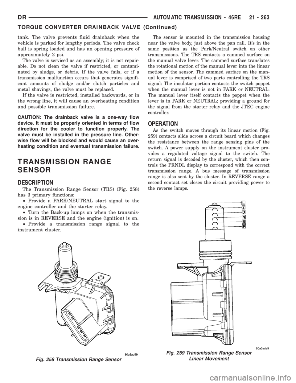
The Transmission Range Sensor (TRS) (Fig. 258)
has 3 primary functions:
²Provide a PARK/NEUTRAL start signal to the
engine controller and the starter relay.
²Turn the Back-up lamps on when the transmis-
sion is in REVERSE and the engine (ignition) is on.
²Provide a transmission range signal to the
instrument cluster.
The sensor is mounted in the transmission housing
near the valve body, just above the pan rail. It's in the
same position as the Park/Neutral switch on other
transmissions. The TRS contacts a cammed surface on
the manual valve lever. The cammed surface translates
the rotational motion of the manual lever into the linear
motion of the sensor. The cammed surface on the man-
ual lever is comprised of two parts controlling the TRS
signal: The insulator portion contacts the switch poppet
when the manual lever is not in PARK or NEUTRAL.
The manual lever itself contacts the poppet when the
lever is in PARK or NEUTRAL; providing a ground for
the signal from the starter relay and the JTEC engine
controller.
OPERATION
As the switch moves through its linear motion (Fig.
259) contacts slide across a circuit board which changes
the resistance between the range sensing pins of the
switch. A power supply on the instrument cluster pro-
vides a regulated voltage signal to the switch. The
return signal is decoded by the cluster, which then con-
trols the PRNDL display to correspond with the correct
transmission range. A bus message of transmission
range is also sent by the cluster. In REVERSE range a
second contact set closes the circuit providing power to
the reverse lamps.
Fig. 258 Transmission Range Sensor
Fig. 259 Transmission Range Sensor
Linear Movement
DRAUTOMATIC TRANSMISSION - 46RE 21 - 263
TORQUE CONVERTER DRAINBACK VALVE (Continued)
Page 2103 of 2895
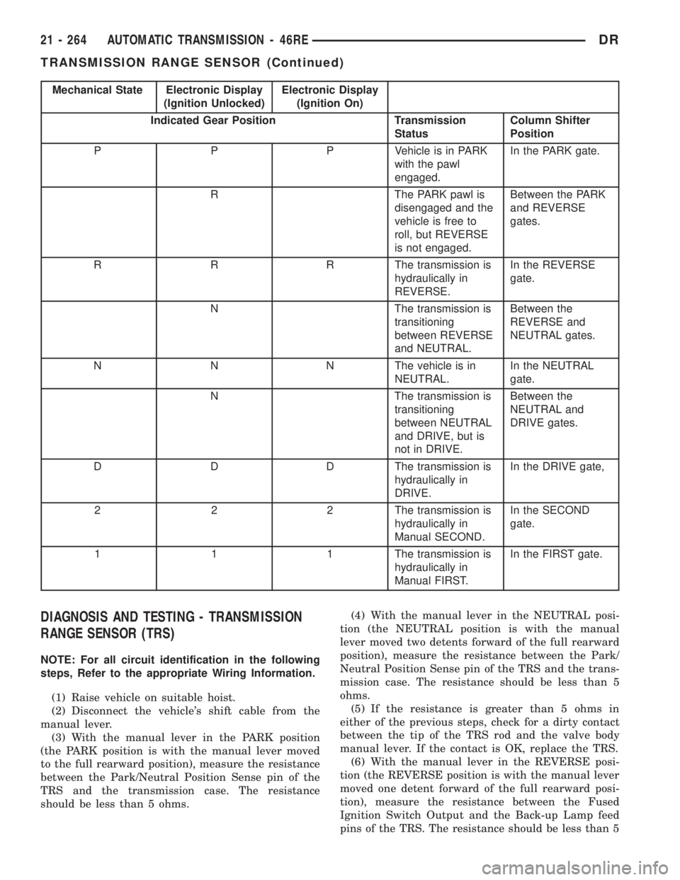
Mechanical State Electronic Display
(Ignition Unlocked)Electronic Display
(Ignition On)
Indicated Gear Position Transmission
StatusColumn Shifter
Position
P P P Vehicle is in PARK
with the pawl
engaged.In the PARK gate.
R The PARK pawl is
disengaged and the
vehicle is free to
roll, but REVERSE
is not engaged.Between the PARK
and REVERSE
gates.
R R R The transmission is
hydraulically in
REVERSE.In the REVERSE
gate.
N The transmission is
transitioning
between REVERSE
and NEUTRAL.Between the
REVERSE and
NEUTRAL gates.
N N N The vehicle is in
NEUTRAL.In the NEUTRAL
gate.
N The transmission is
transitioning
between NEUTRAL
and DRIVE, but is
not in DRIVE.Between the
NEUTRAL and
DRIVE gates.
D D D The transmission is
hydraulically in
DRIVE.In the DRIVE gate,
2 2 2 The transmission is
hydraulically in
Manual SECOND.In the SECOND
gate.
1 1 1 The transmission is
hydraulically in
Manual FIRST.In the FIRST gate.
DIAGNOSIS AND TESTING - TRANSMISSION
RANGE SENSOR (TRS)
NOTE: For all circuit identification in the following
steps, Refer to the appropriate Wiring Information.
(1) Raise vehicle on suitable hoist.
(2) Disconnect the vehicle's shift cable from the
manual lever.
(3) With the manual lever in the PARK position
(the PARK position is with the manual lever moved
to the full rearward position), measure the resistance
between the Park/Neutral Position Sense pin of the
TRS and the transmission case. The resistance
should be less than 5 ohms.(4) With the manual lever in the NEUTRAL posi-
tion (the NEUTRAL position is with the manual
lever moved two detents forward of the full rearward
position), measure the resistance between the Park/
Neutral Position Sense pin of the TRS and the trans-
mission case. The resistance should be less than 5
ohms.
(5) If the resistance is greater than 5 ohms in
either of the previous steps, check for a dirty contact
between the tip of the TRS rod and the valve body
manual lever. If the contact is OK, replace the TRS.
(6) With the manual lever in the REVERSE posi-
tion (the REVERSE position is with the manual lever
moved one detent forward of the full rearward posi-
tion), measure the resistance between the Fused
Ignition Switch Output and the Back-up Lamp feed
pins of the TRS. The resistance should be less than 5
21 - 264 AUTOMATIC TRANSMISSION - 46REDR
TRANSMISSION RANGE SENSOR (Continued)
Page 2104 of 2895
ohms. If the resistance is greater than 5 ohms,
replace the TRS.
(7) With the manual lever in the PARK position
(the PARK position is with the manual lever moved
to the full rearward position), measure the resistance
between the Transmission Range Sensor MUX and
the Transmission Range Sensor 5V Supply pins of
the TRS. The resistance should be 522.2 ohms. If the
resistance is not correct, replace the TRS.
(8) With the manual lever in the REVERSE posi-
tion (the REVERSE position is with the manual lever
moved one detent forward of the full rearward posi-
tion), measure the resistance between the Transmis-
sion Range Sensor MUX and the Transmission Range
Sensor 5V Supply pins of the TRS. The resistance
should be 206.2 ohms. If the resistance is not correct,
replace the TRS.
(9) With the manual lever in the NEUTRAL posi-
tion (the NEUTRAL position is with the manual
lever moved two detents forward of the full rearward
position), measure the resistance between the Trans-
mission Range Sensor MUX and the Transmission
Range Sensor 5V Supply pins of the TRS. The resis-
tance should be 108.6 ohms. If the resistance is not
correct, replace the TRS.
(10) With the manual lever in the DRIVE position
(the DRIVE position is with the manual lever moved
three detents forward of the full rearward position),
measure the resistance between the Transmission
Range Sensor MUX and the Transmission Range
Sensor 5V Supply pins of the TRS. The resistance
should be 59.9 ohms. If the resistance is not correct,
replace the TRS.
(11) With the manual lever in the SECOND posi-
tion (the SECOND position is with the manual lever
moved one detent rearward of the full forward posi-
tion), measure the resistance between the Transmis-
sion Range Sensor MUX and the Back-up Lamp feed
pins of the TRS. The resistance should be 31.9 ohms.
If the resistance is not correct, replace the TRS.
(12) With the manual lever in the LOW position
(the LOW position is with the manual lever moved to
the full forward position), measure the resistance
between the Transmission Range Sensor MUX and
the Back-up Lamp feed pins of the TRS. The resis-
tance should be 13.7 ohms. If the resistance is not
correct, replace the TRS.
REMOVAL
(1) Raise vehicle and position drain pan under the
transmission range sensor (TRS).
(2) Move the transmission manual lever to the
manual LOW position. The manual LOW position is
with the manual lever in the forward-most detent.
(3) Disengage the wiring connector from the TRS.(4) Remove the two screws holding the TRS to the
TRS mounting bracket.
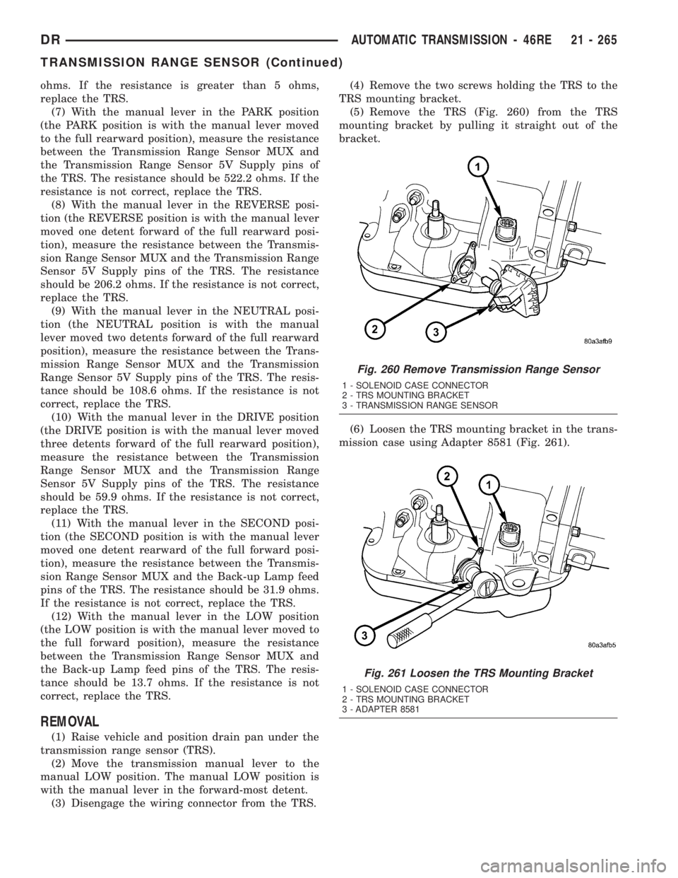
(5) Remove the TRS (Fig. 260) from the TRS
mounting bracket by pulling it straight out of the
bracket.
(6) Loosen the TRS mounting bracket in the trans-
mission case using Adapter 8581 (Fig. 261).
Fig. 260 Remove Transmission Range Sensor
1 - SOLENOID CASE CONNECTOR
2 - TRS MOUNTING BRACKET
3 - TRANSMISSION RANGE SENSOR
Fig. 261 Loosen the TRS Mounting Bracket
1 - SOLENOID CASE CONNECTOR
2 - TRS MOUNTING BRACKET
3 - ADAPTER 8581
DRAUTOMATIC TRANSMISSION - 46RE 21 - 265
TRANSMISSION RANGE SENSOR (Continued)
Page 2105 of 2895
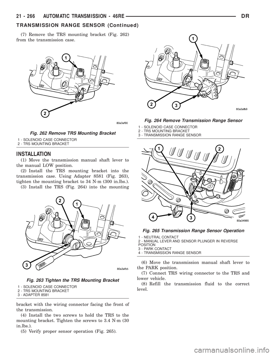
(7) Remove the TRS mounting bracket (Fig. 262)
from the transmission case.
INSTALLATION
(1) Move the transmission manual shaft lever to
the manual LOW position.
(2) Install the TRS mounting bracket into the
transmission case. Using Adapter 8581 (Fig. 263),
tighten the mounting bracket to 34 N´m (300 in.lbs.).
(3) Install the TRS (Fig. 264) into the mounting
bracket with the wiring connector facing the front of
the transmission.
(4) Install the two screws to hold the TRS to the
mounting bracket. Tighten the screws to 3.4 N´m (30
in.lbs.).
(5) Verify proper sensor operation (Fig. 265).(6) Move the transmission manual shaft lever to
the PARK position.
(7) Connect TRS wiring connector to the TRS and
lower vehicle.
(8) Refill the transmission fluid to the correct
level.
Fig. 262 Remove TRS Mounting Bracket
1 - SOLENOID CASE CONNECTOR
2 - TRS MOUNTING BRACKET
Fig. 263 Tighten the TRS Mounting Bracket
1 - SOLENOID CASE CONNECTOR
2 - TRS MOUNTING BRACKET
3 - ADAPTER 8581
Fig. 264 Remove Transmission Range Sensor
1 - SOLENOID CASE CONNECTOR
2 - TRS MOUNTING BRACKET
3 - TRANSMISSION RANGE SENSOR
Fig. 265 Transmission Range Sensor Operation
1 - NEUTRAL CONTACT
2 - MANUAL LEVER AND SENSOR PLUNGER IN REVERSE
POSITION
3 - PARK CONTACT
4 - TRANSMISSION RANGE SENSOR
21 - 266 AUTOMATIC TRANSMISSION - 46REDR
TRANSMISSION RANGE SENSOR (Continued)
Page 2106 of 2895
TRANSMISSION
TEMPERATURE SENSOR
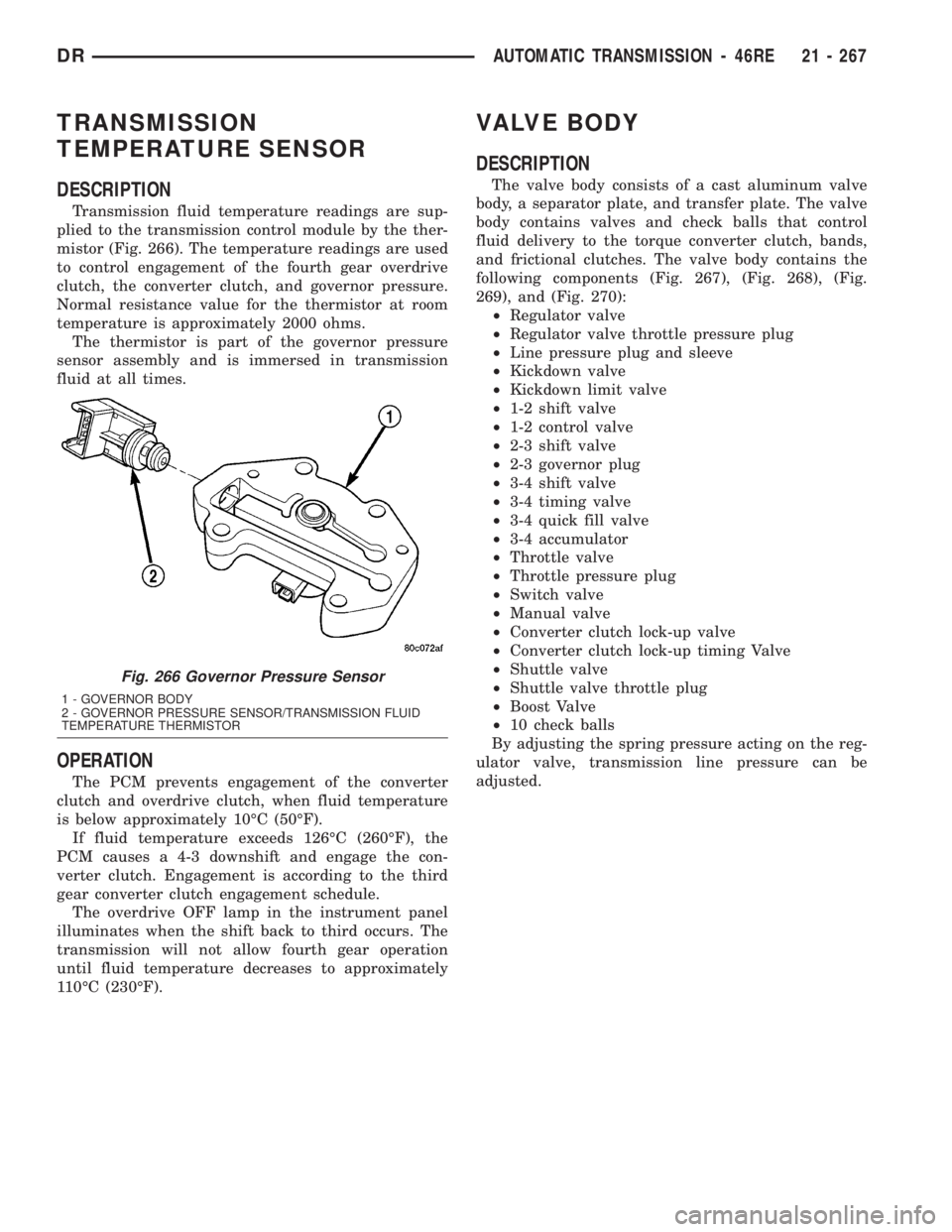
DESCRIPTION
Transmission fluid temperature readings are sup-
plied to the transmission control module by the ther-
mistor (Fig. 266). The temperature readings are used
to control engagement of the fourth gear overdrive
clutch, the converter clutch, and governor pressure.
Normal resistance value for the thermistor at room
temperature is approximately 2000 ohms.
The thermistor is part of the governor pressure
sensor assembly and is immersed in transmission
fluid at all times.
OPERATION
The PCM prevents engagement of the converter
clutch and overdrive clutch, when fluid temperature
is below approximately 10ÉC (50ÉF).
If fluid temperature exceeds 126ÉC (260ÉF), the
PCM causes a 4-3 downshift and engage the con-
verter clutch. Engagement is according to the third
gear converter clutch engagement schedule.
The overdrive OFF lamp in the instrument panel
illuminates when the shift back to third occurs. The
transmission will not allow fourth gear operation
until fluid temperature decreases to approximately
110ÉC (230ÉF).
VALVE BODY
DESCRIPTION
The valve body consists of a cast aluminum valve
body, a separator plate, and transfer plate. The valve
body contains valves and check balls that control
fluid delivery to the torque converter clutch, bands,
and frictional clutches. The valve body contains the
following components (Fig. 267), (Fig. 268), (Fig.
269), and (Fig. 270):
²Regulator valve
²Regulator valve throttle pressure plug
²Line pressure plug and sleeve
²Kickdown valve
²Kickdown limit valve
²1-2 shift valve
²1-2 control valve
²2-3 shift valve
²2-3 governor plug
²3-4 shift valve
²3-4 timing valve
²3-4 quick fill valve
²3-4 accumulator
²Throttle valve
²Throttle pressure plug
²Switch valve
²Manual valve
²Converter clutch lock-up valve
²Converter clutch lock-up timing Valve
²Shuttle valve
²Shuttle valve throttle plug
²Boost Valve
²10 check balls
By adjusting the spring pressure acting on the reg-
ulator valve, transmission line pressure can be
adjusted.
Fig. 266 Governor Pressure Sensor
1 - GOVERNOR BODY
2 - GOVERNOR PRESSURE SENSOR/TRANSMISSION FLUID
TEMPERATURE THERMISTOR
DRAUTOMATIC TRANSMISSION - 46RE 21 - 267
Page 2125 of 2895
BOOST VALVE
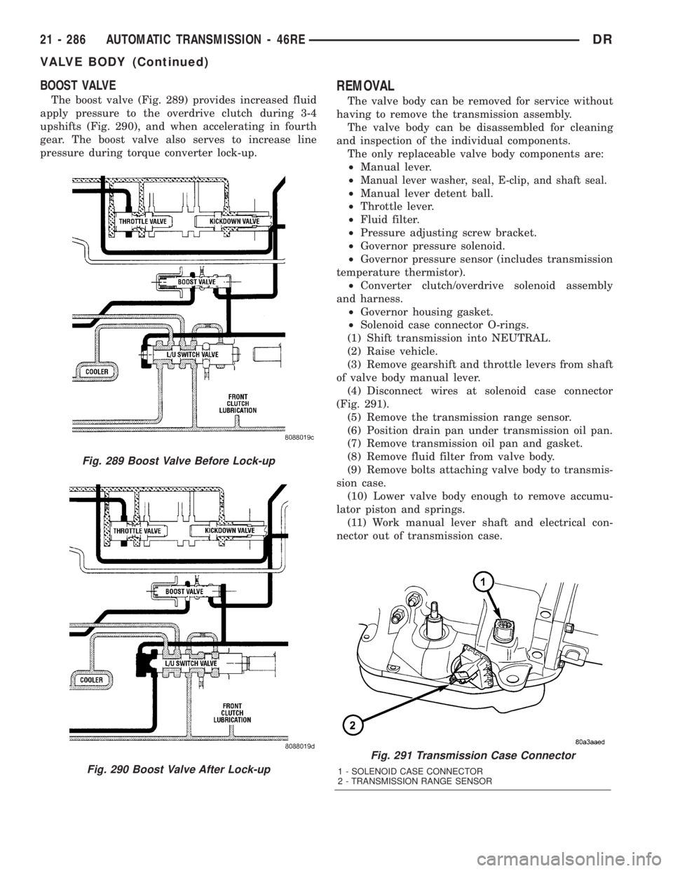
The boost valve (Fig. 289) provides increased fluid
apply pressure to the overdrive clutch during 3-4
upshifts (Fig. 290), and when accelerating in fourth
gear. The boost valve also serves to increase line
pressure during torque converter lock-up.
REMOVAL
The valve body can be removed for service without
having to remove the transmission assembly.
The valve body can be disassembled for cleaning
and inspection of the individual components.
The only replaceable valve body components are:
²Manual lever.
²
Manual lever washer, seal, E-clip, and shaft seal.
²Manual lever detent ball.
²Throttle lever.
²Fluid filter.
²Pressure adjusting screw bracket.
²Governor pressure solenoid.
²Governor pressure sensor (includes transmission
temperature thermistor).
²Converter clutch/overdrive solenoid assembly
and harness.
²Governor housing gasket.
²Solenoid case connector O-rings.
(1) Shift transmission into NEUTRAL.
(2) Raise vehicle.
(3) Remove gearshift and throttle levers from shaft
of valve body manual lever.
(4) Disconnect wires at solenoid case connector
(Fig. 291).
(5) Remove the transmission range sensor.
(6) Position drain pan under transmission oil pan.
(7) Remove transmission oil pan and gasket.
(8) Remove fluid filter from valve body.
(9) Remove bolts attaching valve body to transmis-
sion case.
(10) Lower valve body enough to remove accumu-
lator piston and springs.
(11) Work manual lever shaft and electrical con-
nector out of transmission case.
Fig. 291 Transmission Case Connector
1 - SOLENOID CASE CONNECTOR
2 - TRANSMISSION RANGE SENSOR
Fig. 289 Boost Valve Before Lock-up
Fig. 290 Boost Valve After Lock-up
21 - 286 AUTOMATIC TRANSMISSION - 46REDR
VALVE BODY (Continued)
Page 2126 of 2895
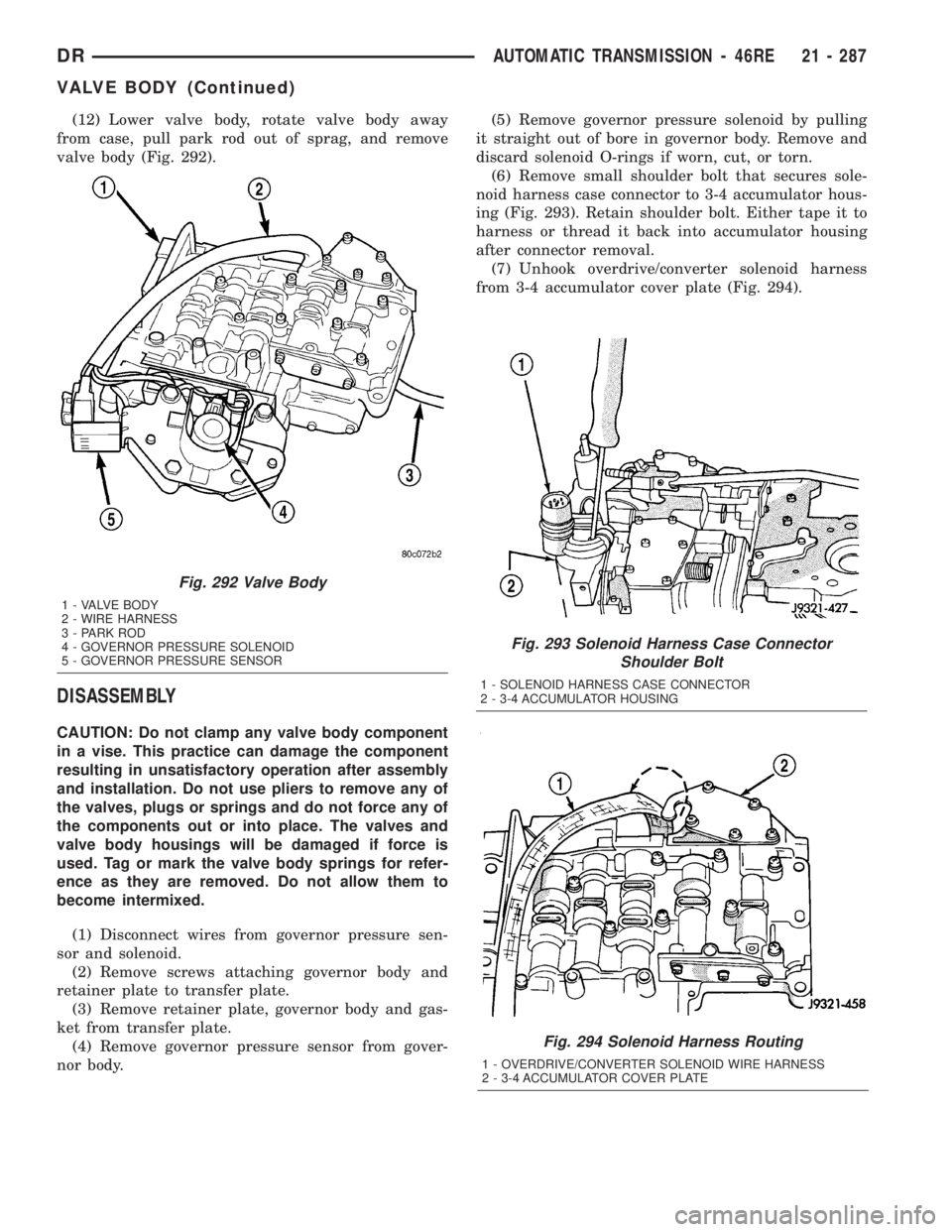
(12) Lower valve body, rotate valve body away
from case, pull park rod out of sprag, and remove
valve body (Fig. 292).
DISASSEMBLY
CAUTION: Do not clamp any valve body component
in a vise. This practice can damage the component
resulting in unsatisfactory operation after assembly
and installation. Do not use pliers to remove any of
the valves, plugs or springs and do not force any of
the components out or into place. The valves and
valve body housings will be damaged if force is
used. Tag or mark the valve body springs for refer-
ence as they are removed. Do not allow them to
become intermixed.
(1) Disconnect wires from governor pressure sen-
sor and solenoid.
(2) Remove screws attaching governor body and
retainer plate to transfer plate.
(3) Remove retainer plate, governor body and gas-
ket from transfer plate.
(4) Remove governor pressure sensor from gover-
nor body.(5) Remove governor pressure solenoid by pulling
it straight out of bore in governor body. Remove and
discard solenoid O-rings if worn, cut, or torn.
(6) Remove small shoulder bolt that secures sole-
noid harness case connector to 3-4 accumulator hous-
ing (Fig. 293). Retain shoulder bolt. Either tape it to
harness or thread it back into accumulator housing
after connector removal.
(7) Unhook overdrive/converter solenoid harness
from 3-4 accumulator cover plate (Fig. 294).
Fig. 293 Solenoid Harness Case Connector
Shoulder Bolt
1 - SOLENOID HARNESS CASE CONNECTOR
2 - 3-4 ACCUMULATOR HOUSING
Fig. 294 Solenoid Harness Routing
1 - OVERDRIVE/CONVERTER SOLENOID WIRE HARNESS
2 - 3-4 ACCUMULATOR COVER PLATE
Fig. 292 Valve Body
1 - VALVE BODY
2 - WIRE HARNESS
3 - PARK ROD
4 - GOVERNOR PRESSURE SOLENOID
5 - GOVERNOR PRESSURE SENSOR
DRAUTOMATIC TRANSMISSION - 46RE 21 - 287
VALVE BODY (Continued)
Page 2127 of 2895
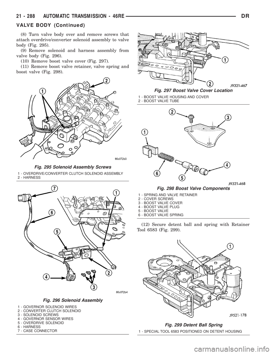
(8) Turn valve body over and remove screws that
attach overdrive/converter solenoid assembly to valve
body (Fig. 295).
(9) Remove solenoid and harness assembly from
valve body (Fig. 296).
(10) Remove boost valve cover (Fig. 297).
(11) Remove boost valve retainer, valve spring and
boost valve (Fig. 298).
(12) Secure detent ball and spring with Retainer
Tool 6583 (Fig. 299).
Fig. 299 Detent Ball Spring
1 - SPECIAL TOOL 6583 POSITIONED ON DETENT HOUSING
Fig. 295 Solenoid Assembly Screws
1 - OVERDRIVE/CONVERTER CLUTCH SOLENOID ASSEMBLY
2 - HARNESS
Fig. 296 Solenoid Assembly
1 - GOVERNOR SOLENOID WIRES
2 - CONVERTER CLUTCH SOLENOID
3 - SOLENOID SCREWS
4 - GOVERNOR SENSOR WIRES
5 - OVERDRIVE SOLENOID
6 - HARNESS
7 - CASE CONNECTOR
Fig. 297 Boost Valve Cover Location
1 - BOOST VALVE HOUSING AND COVER
2 - BOOST VALVE TUBE
Fig. 298 Boost Valve Components
1 - SPRING AND VALVE RETAINER
2 - COVER SCREWS
3 - BOOST VALVE COVER
4 - BOOST VALVE PLUG
5 - BOOST VALVE
6 - BOOST VALVE SPRING
21 - 288 AUTOMATIC TRANSMISSION - 46REDR
VALVE BODY (Continued)
Page 2137 of 2895
CLEANING
Clean the valve housings, valves, plugs, springs,
and separator plates with a standard parts cleaning
solution only. Do not use gasoline, kerosene, or any
type of caustic solution.
Do not immerse any of the electrical components in
cleaning solution. Clean the governor solenoid and
sensor and the dual solenoid and harness assembly
by wiping them off with dry shop towels only.
Dry all except the electrical parts with compressed
air. Make sure all passages are clean and free from
obstructions.Do not use rags or shop towels to
dry or wipe off valve body components. Lint
from these materials can stick to valve body
parts, interfere with valve operation, and clog
filters and fluid passages.
Wipe the governor pressure sensor and solenoid
valve with dry, lint free shop towels only. The O-rings
on the sensor and solenoid valve are the only service-
able components. Be sure the vent ports in the sole-
noid valve are open and not blocked by dirt or debris.
Replace the valve and/or sensor only when DRB scan
tool diagnosis indicates this is necessary. Or, if either
part has sustained physical damage (dented,
deformed, broken, etc.).
CAUTION: Do not turn the small screw at the end of
the solenoid valve for any reason. Turning the
screw in either direction will ruin solenoid calibra-
tion and result in solenoid failure. In addition, thefilter on the solenoid valve is NOT serviceable. Do
not try to remove the filter as this will damage the
valve housing.
INSPECTION
Inspect the throttle and manual valve levers and
shafts. Do not attempt to straighten a bent shaft or
correct a loose lever. Replace these components if
worn, bent, loose or damaged in any way.
Inspect all of the valve body mating surfaces for
scratches, nicks, burrs, or distortion. Use a straight-
edge to check surface flatness. Minor scratches may
be removed with crocus cloth using only very light
pressure.
Minor distortion of a valve body mating surface
may be corrected by smoothing the surface with a
sheet of crocus cloth. Position the crocus cloth on a
surface plate, sheet of plate glass or equally flat sur-
face. If distortion is severe or any surfaces are
heavily scored, the valve body will have to be
replaced.
CAUTION: Many of the valves and plugs, such as
the throttle valve, shuttle valve plug, 1-2 shift valve
and 1-2 governor plug, are made of coated alumi-
num. Aluminum components are identified by the
dark color of the special coating applied to the sur-
face (or by testing with a magnet). Do not sand alu-
minum valves or plugs under any circumstances.
This practice could damage the special coating
causing the valves/plugs to stick and bind.
Inspect the valves and plugs for scratches, burrs,
nicks, or scores. Minor surface scratches on steel
valves and plugs can be removed with crocus cloth
butdo not round off the edges of the valve or
plug lands.Maintaining sharpness of these edges is
vitally important. The edges prevent foreign matter
from lodging between the valves and plugs and the
bore.
Inspect all the valve and plug bores in the valve
body. Use a penlight to view the bore interiors.
Replace the valve body if any bores are distorted or
scored. Inspect all of the valve body springs. The
springs must be free of distortion, warpage or broken
coils.
Check the two separator plates for distortion or
damage of any kind. Inspect the upper housing,
lower housing, 3-4 accumulator housing, and transfer
plate carefully. Be sure all fluid passages are clean
and clear. Check condition of the upper housing and
transfer plate check balls as well. The check balls
and ball seats must not be worn or damaged.
Trial fit each valve and plug in its bore to check
freedom of operation. When clean and dry, the valves
and plugs should drop freely into the bores.
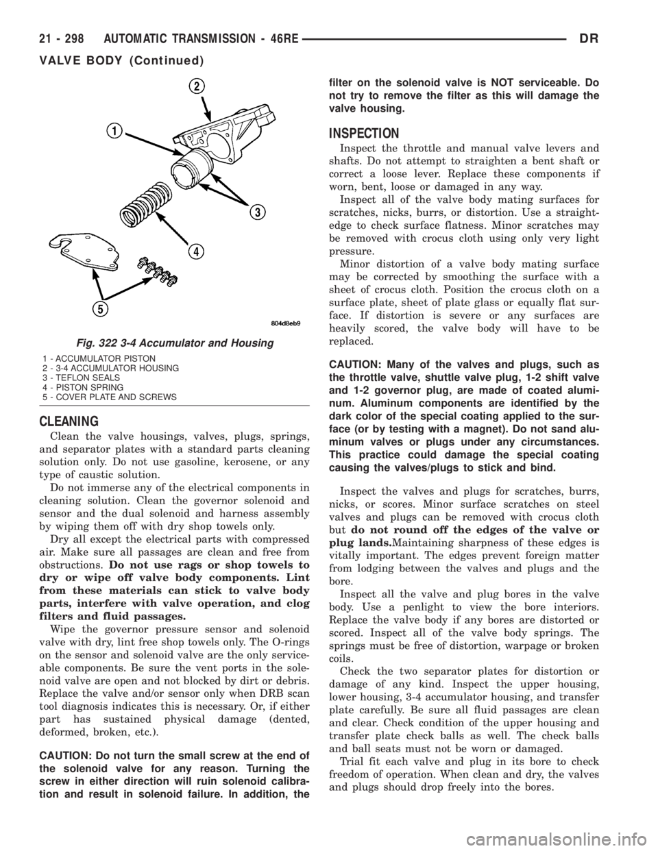
Fig. 322 3-4 Accumulator and Housing
1 - ACCUMULATOR PISTON
2 - 3-4 ACCUMULATOR HOUSING
3 - TEFLON SEALS
4 - PISTON SPRING
5 - COVER PLATE AND SCREWS
21 - 298 AUTOMATIC TRANSMISSION - 46REDR
VALVE BODY (Continued)
Page 2138 of 2895
Valve body bores do not change dimensionally with
use. If the valve body functioned correctly when new,
it will continue to operate properly after cleaning and
inspection. It should not be necessary to replace a
valve body assembly unless it is damaged in han-
dling.
The only serviceable valve body components are
listed below. The remaining valve body components
are serviced only as part of a complete valve body
assembly. Serviceable parts are:
²dual solenoid and harness assembly
²solenoid gasket
²solenoid case connector O-rings and shoulder
bolt
²switch valve and spring
²pressure adjusting screw and bracket assembly
²throttle lever
²manual lever and shaft seal
²throttle lever shaft seal, washer, and E-clip
²fluid filter and screws
²detent ball and spring
²valve body screws
²governor pressure solenoid
²governor pressure sensor and retaining clip
²park lock rod and E-clip
ASSEMBLY
CAUTION: Do not force valves or plugs into place
during reassembly. If the valve body bores, valves
and plugs are free of distortion or burrs, the valve
body components should all slide into place easily.
In addition, do not overtighten the transfer plate
and valve body screws during reassembly. Over-
tightening can distort the housings resulting in
valve sticking, cross leakage and unsatisfactory
operation. Tighten valve body screws to recom-
mended torque only.
LOWER HOUSING
(1) Lubricate valves, springs, and the housing
valve and plug bores with clean transmission fluid
(Fig. 321).
(2) Install 3-4 timing valve spring and valve in
lower housing.
(3) Install 3-4 quick fill valve in lower housing.
(4) Install 3-4 quick fill valve spring and plug in
housing.
(5) Install timing valve end plate. Tighten end
plate screws to 4 N´m (35 in. lbs.) torque.
3-4 ACCUMULATOR
(1) Lubricate accumulator piston, seals and hous-
ing piston bore with clean transmission fluid (Fig.
322).
(2) Install new seal rings on accumulator piston.
(3) Install piston and spring in housing.
(4) Install end plate on housing.
TRANSFER PLATE
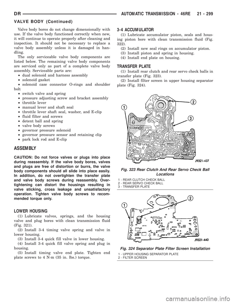
(1) Install rear clutch and rear servo check balls in
transfer plate (Fig. 323).
(2) Install filter screen in upper housing separator
plate (Fig. 324).
Fig. 323 Rear Clutch And Rear Servo Check Ball
Locations
1 - REAR CLUTCH CHECK BALL
2 - REAR SERVO CHECK BALL
3 - TRANSFER PLATE
Fig. 324 Separator Plate Filter Screen Installation
1 - UPPER HOUSING SEPARATOR PLATE
2 - FILTER SCREEN
DRAUTOMATIC TRANSMISSION - 46RE 21 - 299
VALVE BODY (Continued)