intake manifold DODGE RAM 2003 Service Owner's Guide
[x] Cancel search | Manufacturer: DODGE, Model Year: 2003, Model line: RAM, Model: DODGE RAM 2003Pages: 2895, PDF Size: 83.15 MB
Page 1136 of 2895

INSTRUMENT CLUSTER C3 - WHITE 26 WAY
CAV CIRCUIT FUNCTION
1 M3 20 PK/DB CARGO LAMP DRIVER
2- -
3 M20 20BR COURTESY LAMP DRIVER
4 M11 20PK/LB COURTESY LAMP GROUND
5- -
6 Y165 20OR/YL PANEL LAMPS DRIVER
7- -
8 Y108 20VT/BR WIPER/TURN/BEAM SELECT SWITCH RETURN
9 Y167 20WT/DB HEADLAMP SWITCH RETURN
10 Y128 20DG/GY TRANS RANGE SENSOR ELECTRONIC CLUSTER 5
VOLT SUPPLY
11 Z202 20LB/BK GROUND
12 Z203 20VT/BK GROUND
13 Y105 20BK/RD FUSED IGNITION SWITCH OUTPUT (RUN-ACC)
14 E1 20TN FUSED B(+)
15 P131 20RD/DG (ELECTRIC 4X4) HEATED SEAT SWITCH SUPPLY
16 Y189 20OR/BK (SLT+) PANEL LAMPS FEED
17 Y161 20OR/RD (ELECTRIC 4X4) PANEL LAMPS FEED
18 Y163 20OR/WT HEADLAMP SWITCH ILLUMINATION CONTROL
19 Y166 20OR/DB PANEL LAMPS DRIVER
20 - -
21 D25 20VT/YL PCI BUS
22 G11 20WT/LG PARK BRAKE SWITCH SENSE
23 Z106 20LG/BK GROUND
24 A51 16RD/WT IGNITION SWITCH OUTPUT (OFF-RUN-START)
25 Y107 20VT/RD FUSED IGNITION SWITCH OUTPUT (RUN-START)
26 M1 18PK FUSED B(+)
INTAKE AIR TEMPERATURE SENSOR - BLACK 2 WAY
CAV CIRCUIT FUNCTION
1 K4 18BK/LB SENSOR GROUND
2 K21 18BK/RD INTAKE AIR TEMPERATURE SENSOR SIGNAL
INTAKE AIR TEMPERATURE/MANIFOLD ABSOLUTE PRESSURE SENSOR (DIESEL)-4WAY
CAV CIRCUIT FUNCTION
A K55 18LB/WT MAP SENSOR SIGNAL
B K21 18BK/RD INTAKE AIR TEMPERATURE SENSOR SIGNAL
C K72 18DG/OR 5 VOLT SUPPLY
D K9 18LB 5 VOLT SUPPLY
DR8W-80 CONNECTOR PIN-OUTS 8W - 80 - 69
Page 1154 of 2895
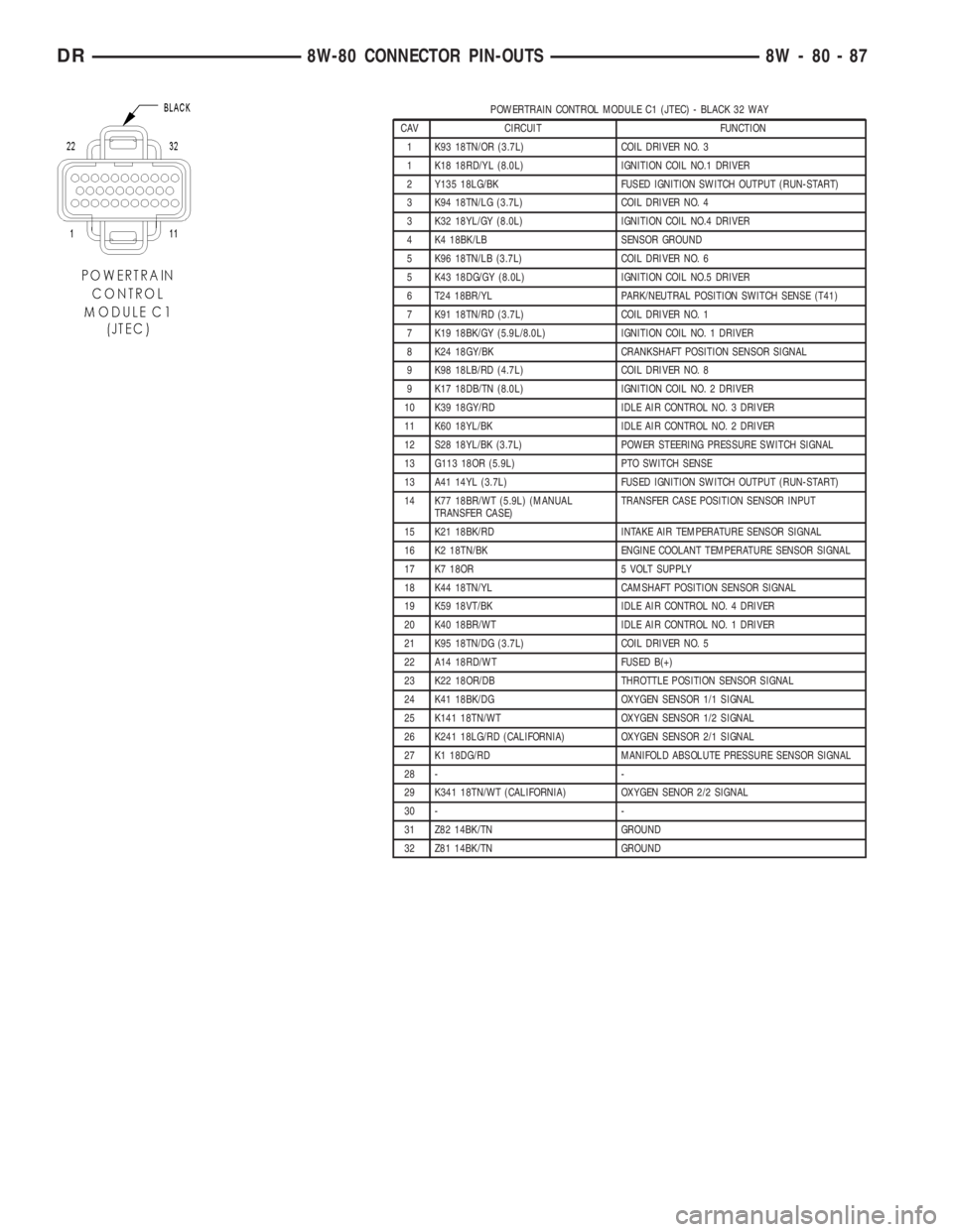
POWERTRAIN CONTROL MODULE C1 (JTEC) - BLACK 32 WAY
CAV CIRCUIT FUNCTION
1 K93 18TN/OR (3.7L) COIL DRIVER NO. 3
1 K18 18RD/YL (8.0L) IGNITION COIL NO.1 DRIVER
2 Y135 18LG/BK FUSED IGNITION SWITCH OUTPUT (RUN-START)
3 K94 18TN/LG (3.7L) COIL DRIVER NO. 4
3 K32 18YL/GY (8.0L) IGNITION COIL NO.4 DRIVER
4 K4 18BK/LB SENSOR GROUND
5 K96 18TN/LB (3.7L) COIL DRIVER NO. 6
5 K43 18DG/GY (8.0L) IGNITION COIL NO.5 DRIVER
6 T24 18BR/YL PARK/NEUTRAL POSITION SWITCH SENSE (T41)
7 K91 18TN/RD (3.7L) COIL DRIVER NO. 1
7 K19 18BK/GY (5.9L/8.0L) IGNITION COIL NO. 1 DRIVER
8 K24 18GY/BK CRANKSHAFT POSITION SENSOR SIGNAL
9 K98 18LB/RD (4.7L) COIL DRIVER NO. 8
9 K17 18DB/TN (8.0L) IGNITION COIL NO. 2 DRIVER
10 K39 18GY/RD IDLE AIR CONTROL NO. 3 DRIVER
11 K60 18YL/BK IDLE AIR CONTROL NO. 2 DRIVER
12 S28 18YL/BK (3.7L) POWER STEERING PRESSURE SWITCH SIGNAL
13 G113 18OR (5.9L) PTO SWITCH SENSE
13 A41 14YL (3.7L) FUSED IGNITION SWITCH OUTPUT (RUN-START)
14 K77 18BR/WT (5.9L) (MANUAL
TRANSFER CASE)TRANSFER CASE POSITION SENSOR INPUT
15 K21 18BK/RD INTAKE AIR TEMPERATURE SENSOR SIGNAL
16 K2 18TN/BK ENGINE COOLANT TEMPERATURE SENSOR SIGNAL
17 K7 18OR 5 VOLT SUPPLY
18 K44 18TN/YL CAMSHAFT POSITION SENSOR SIGNAL
19 K59 18VT/BK IDLE AIR CONTROL NO. 4 DRIVER
20 K40 18BR/WT IDLE AIR CONTROL NO. 1 DRIVER
21 K95 18TN/DG (3.7L) COIL DRIVER NO. 5
22 A14 18RD/WT FUSED B(+)
23 K22 18OR/DB THROTTLE POSITION SENSOR SIGNAL
24 K41 18BK/DG OXYGEN SENSOR 1/1 SIGNAL
25 K141 18TN/WT OXYGEN SENSOR 1/2 SIGNAL
26 K241 18LG/RD (CALIFORNIA) OXYGEN SENSOR 2/1 SIGNAL
27 K1 18DG/RD MANIFOLD ABSOLUTE PRESSURE SENSOR SIGNAL
28 - -
29 K341 18TN/WT (CALIFORNIA) OXYGEN SENOR 2/2 SIGNAL
30 - -
31 Z82 14BK/TN GROUND
32 Z81 14BK/TN GROUND
DR8W-80 CONNECTOR PIN-OUTS 8W - 80 - 87
Page 1180 of 2895
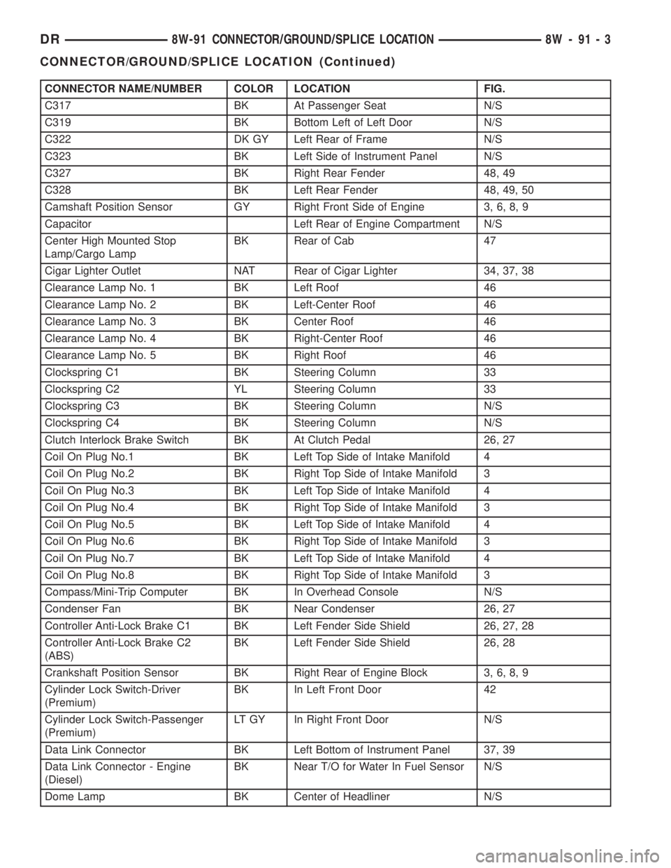
CONNECTOR NAME/NUMBER COLOR LOCATION FIG.
C317 BK At Passenger Seat N/S
C319 BK Bottom Left of Left Door N/S
C322 DK GY Left Rear of Frame N/S
C323 BK Left Side of Instrument Panel N/S
C327 BK Right Rear Fender 48, 49
C328 BK Left Rear Fender 48, 49, 50
Camshaft Position Sensor GY Right Front Side of Engine 3, 6, 8, 9
Capacitor Left Rear of Engine Compartment N/S
Center High Mounted Stop
Lamp/Cargo LampBK Rear of Cab 47
Cigar Lighter Outlet NAT Rear of Cigar Lighter 34, 37, 38
Clearance Lamp No. 1 BK Left Roof 46
Clearance Lamp No. 2 BK Left-Center Roof 46
Clearance Lamp No. 3 BK Center Roof 46
Clearance Lamp No. 4 BK Right-Center Roof 46
Clearance Lamp No. 5 BK Right Roof 46
Clockspring C1 BK Steering Column 33
Clockspring C2 YL Steering Column 33
Clockspring C3 BK Steering Column N/S
Clockspring C4 BK Steering Column N/S
Clutch Interlock Brake Switch BK At Clutch Pedal 26, 27
Coil On Plug No.1 BK Left Top Side of Intake Manifold 4
Coil On Plug No.2 BK Right Top Side of Intake Manifold 3
Coil On Plug No.3 BK Left Top Side of Intake Manifold 4
Coil On Plug No.4 BK Right Top Side of Intake Manifold 3
Coil On Plug No.5 BK Left Top Side of Intake Manifold 4
Coil On Plug No.6 BK Right Top Side of Intake Manifold 3
Coil On Plug No.7 BK Left Top Side of Intake Manifold 4
Coil On Plug No.8 BK Right Top Side of Intake Manifold 3
Compass/Mini-Trip Computer BK In Overhead Console N/S
Condenser Fan BK Near Condenser 26, 27
Controller Anti-Lock Brake C1 BK Left Fender Side Shield 26, 27, 28
Controller Anti-Lock Brake C2
(ABS)BK Left Fender Side Shield 26, 28
Crankshaft Position Sensor BK Right Rear of Engine Block 3, 6, 8, 9
Cylinder Lock Switch-Driver
(Premium)BK In Left Front Door 42
Cylinder Lock Switch-Passenger
(Premium)LT GY In Right Front Door N/S
Data Link Connector BK Left Bottom of Instrument Panel 37, 39
Data Link Connector - Engine
(Diesel)BK Near T/O for Water In Fuel Sensor N/S
Dome Lamp BK Center of Headliner N/S
DR8W-91 CONNECTOR/GROUND/SPLICE LOCATION 8W - 91 - 3
CONNECTOR/GROUND/SPLICE LOCATION (Continued)
Page 1182 of 2895
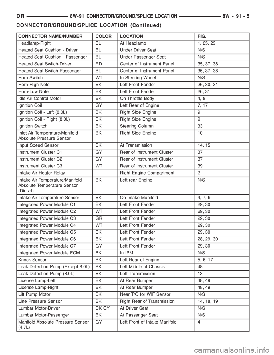
CONNECTOR NAME/NUMBER COLOR LOCATION FIG.
Headlamp-Right BL At Headlamp 1, 25, 29
Heated Seat Cushion - Driver BL Under Driver Seat N/S
Heated Seat Cushion - Passenger BL Under Passenger Seat N/S
Heated Seat Switch-Driver RD Center of Instrument Panel 35, 37, 38
Heated Seat Switch-Passenger BL Center of Instrument Panel 35, 37, 38
Horn Switch WT In Steering Wheel N/S
Horn-High Note BK Left Front Fender 26, 30, 31
Horn-Low Note BK Left Front Fender 26, 31
Idle Air Control Motor BK On Throttle Body 4, 8
Ignition Coil GY Left Rear of Engine 7, 17
Ignition Coil - Left (8.0L) BK Right Side Engine 9
Ignition Coil - Right (8.0L) BK Right Side Engine 9
Ignition Switch BK Steering Column 33
Inlet Air Temperature/Manifold
Absolute Pressure SensorBK Right Side Engine 10
Input Speed Sensor BK At Transmission 14, 15
Instrument Cluster C1 GY Rear of Instrument Cluster 37
Instrument Cluster C2 GY Rear of Instrument Cluster 37
Instrument Cluster C3 WT Rear of Instrument Cluster 39
Intake Air Heater Relay Right Engine Compartment 2
Intake Air Temperature/Manifold
Absolute Temperature Sensor
(Diesel)BK Left rear Engine N/S
Intake Air Temperature Sensor BK On Intake Manifold 4, 7, 9
Integrated Power Module C1 BK Left Front Fender 29, 30
Integrated Power Module C2 WT Left Front Fender 29, 30
Integrated Power Module C3 GR Left Front Fender 29, 30
Integrated Power Module C4 WT Left Front Fender 29, 30
Integrated Power Module C5 BK Left Front Fender 29, 30
Integrated Power Module C6 BK Left Front Fender 28, 29, 30
Integrated Power Module C7 GY Left Front Fender 29, 30
Integrated Power Module FCM BK In IPM N/S
Knock Sensor BK Left Rear of Engine 5, 6, 17
Leak Detection Pump (Except 8.0L) BK Left Middle of Chassis 48
Leak Detection Pump (8.0L) BK Left Transmission 13
License Lamp-Left BK At Rear Bumper 48, 49
License Lamp-Right BK At Rear Bumper 48, 49
Lift Pump Motor BK Near T/O for WIF Sensor N/S
Line Pressure Sensor BK Right Rear of Transmission 14, 18, 19
Lumbar Motor-Driver DK GY At Driver Seat N/S
Lumbar Motor-Passenger BK At Passenger Seat N/S
Manifold Absolute Pressure Sensor
(4.7L)GY Left Front of Intake Manifold 4
DR8W-91 CONNECTOR/GROUND/SPLICE LOCATION 8W - 91 - 5
CONNECTOR/GROUND/SPLICE LOCATION (Continued)
Page 1183 of 2895
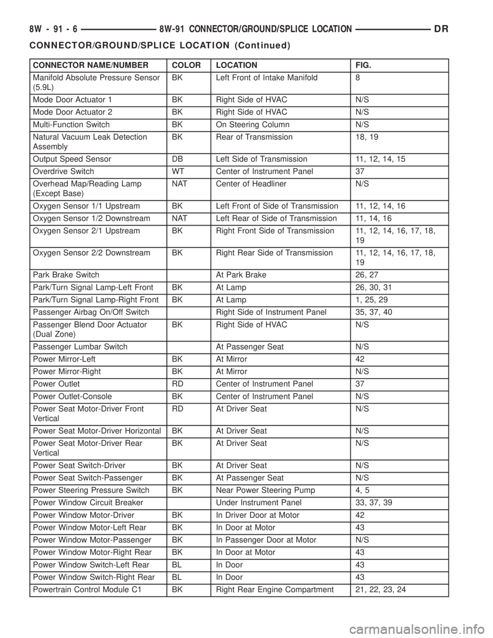
CONNECTOR NAME/NUMBER COLOR LOCATION FIG.
Manifold Absolute Pressure Sensor
(5.9L)BK Left Front of Intake Manifold 8
Mode Door Actuator 1 BK Right Side of HVAC N/S
Mode Door Actuator 2 BK Right Side of HVAC N/S
Multi-Function Switch BK On Steering Column N/S
Natural Vacuum Leak Detection
AssemblyBK Rear of Transmission 18, 19
Output Speed Sensor DB Left Side of Transmission 11, 12, 14, 15
Overdrive Switch WT Center of Instrument Panel 37
Overhead Map/Reading Lamp
(Except Base)NAT Center of Headliner N/S
Oxygen Sensor 1/1 Upstream BK Left Front of Side of Transmission 11, 12, 14, 16
Oxygen Sensor 1/2 Downstream NAT Left Rear of Side of Transmission 11, 14, 16
Oxygen Sensor 2/1 Upstream BK Right Front Side of Transmission 11, 12, 14, 16, 17, 18,
19
Oxygen Sensor 2/2 Downstream BK Right Rear Side of Transmission 11, 12, 14, 16, 17, 18,
19
Park Brake Switch At Park Brake 26, 27
Park/Turn Signal Lamp-Left Front BK At Lamp 26, 30, 31
Park/Turn Signal Lamp-Right Front BK At Lamp 1, 25, 29
Passenger Airbag On/Off Switch Right Side of Instrument Panel 35, 37, 40
Passenger Blend Door Actuator
(Dual Zone)BK Right Side of HVAC N/S
Passenger Lumbar Switch At Passenger Seat N/S
Power Mirror-Left BK At Mirror 42
Power Mirror-Right BK At Mirror N/S
Power Outlet RD Center of Instrument Panel 37
Power Outlet-Console BK Center of Instrument Panel N/S
Power Seat Motor-Driver Front
VerticalRD At Driver Seat N/S
Power Seat Motor-Driver Horizontal BK At Driver Seat N/S
Power Seat Motor-Driver Rear
VerticalBK At Driver Seat N/S
Power Seat Switch-Driver BK At Driver Seat N/S
Power Seat Switch-Passenger BK At Passenger Seat N/S
Power Steering Pressure Switch BK Near Power Steering Pump 4, 5
Power Window Circuit Breaker Under Instrument Panel 33, 37, 39
Power Window Motor-Driver BK In Driver Door at Motor 42
Power Window Motor-Left Rear BK In Door at Motor 43
Power Window Motor-Passenger BK In Passenger Door at Motor N/S
Power Window Motor-Right Rear BK In Door at Motor 43
Power Window Switch-Left Rear BL In Door 43
Power Window Switch-Right Rear BL In Door 43
Powertrain Control Module C1 BK Right Rear Engine Compartment 21, 22, 23, 24
8W - 91 - 6 8W-91 CONNECTOR/GROUND/SPLICE LOCATIONDR
CONNECTOR/GROUND/SPLICE LOCATION (Continued)
Page 1251 of 2895
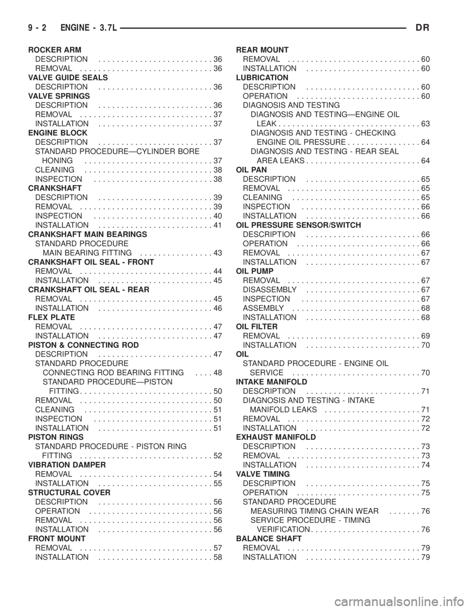
ROCKER ARM
DESCRIPTION.........................36
REMOVAL.............................36
VALVE GUIDE SEALS
DESCRIPTION.........................36
VALVE SPRINGS
DESCRIPTION.........................36
REMOVAL.............................37
INSTALLATION.........................37
ENGINE BLOCK
DESCRIPTION.........................37
STANDARD PROCEDUREÐCYLINDER BORE
HONING............................37
CLEANING............................38
INSPECTION..........................38
CRANKSHAFT
DESCRIPTION.........................39
REMOVAL.............................39
INSPECTION..........................40
INSTALLATION.........................41
CRANKSHAFT MAIN BEARINGS
STANDARD PROCEDURE
MAIN BEARING FITTING................43
CRANKSHAFT OIL SEAL - FRONT
REMOVAL.............................44
INSTALLATION.........................45
CRANKSHAFT OIL SEAL - REAR
REMOVAL.............................45
INSTALLATION.........................46
FLEX PLATE
REMOVAL.............................47
INSTALLATION.........................47
PISTON & CONNECTING ROD
DESCRIPTION.........................47
STANDARD PROCEDURE
CONNECTING ROD BEARING FITTING....48
STANDARD PROCEDUREÐPISTON
FITTING.............................50
REMOVAL.............................50
CLEANING............................51
INSPECTION..........................51
INSTALLATION.........................51
PISTON RINGS
STANDARD PROCEDURE - PISTON RING
FITTING.............................52
VIBRATION DAMPER
REMOVAL.............................54
INSTALLATION.........................55
STRUCTURAL COVER
DESCRIPTION.........................56
OPERATION...........................56
REMOVAL.............................56
INSTALLATION.........................56
FRONT MOUNT
REMOVAL.............................57
INSTALLATION.........................58REAR MOUNT
REMOVAL.............................60
INSTALLATION.........................60
LUBRICATION
DESCRIPTION.........................60
OPERATION...........................60
DIAGNOSIS AND TESTING
DIAGNOSIS AND TESTINGÐENGINE OIL
LEAK...............................63
DIAGNOSIS AND TESTING - CHECKING
ENGINE OIL PRESSURE................64
DIAGNOSIS AND TESTING - REAR SEAL
AREA LEAKS.........................64
OIL PAN
DESCRIPTION.........................65
REMOVAL.............................65
CLEANING............................65
INSPECTION..........................66
INSTALLATION.........................66
OIL PRESSURE SENSOR/SWITCH
DESCRIPTION.........................66
OPERATION...........................66
REMOVAL.............................67
INSTALLATION.........................67
OIL PUMP
REMOVAL.............................67
DISASSEMBLY.........................67
INSPECTION..........................67
ASSEMBLY............................68
INSTALLATION.........................68
OIL FILTER
REMOVAL.............................69
INSTALLATION.........................70
OIL
STANDARD PROCEDURE - ENGINE OIL
SERVICE............................70
INTAKE MANIFOLD
DESCRIPTION.........................71
DIAGNOSIS AND TESTING - INTAKE
MANIFOLD LEAKS.....................71
REMOVAL.............................72
INSTALLATION.........................72
EXHAUST MANIFOLD
DESCRIPTION.........................73
REMOVAL.............................73
INSTALLATION.........................74
VALVE TIMING
DESCRIPTION.........................75
OPERATION...........................75
STANDARD PROCEDURE
MEASURING TIMING CHAIN WEAR.......76
SERVICE PROCEDURE - TIMING
VERIFICATION........................76
BALANCE SHAFT
REMOVAL.............................79
INSTALLATION.........................79
9 - 2 ENGINE - 3.7LDR
Page 1253 of 2895
DIAGNOSIS AND TESTING
DIAGNOSIS AND TESTING - ENGINE
DIAGNOSIS - INTRODUCTION
Engine diagnosis is helpful in determining the
causes of malfunctions not detected and remedied by
routine maintenance.
These malfunctions may be classified as either per-
formance (e.g., engine idles rough and stalls) or
mechanical (e.g., a strange noise).
(Refer to 9 - ENGINE - DIAGNOSIS AND TEST-
ING)ÐPERFORMANCE and (Refer to 9 - ENGINE -
DIAGNOSIS AND TESTING)ÐMECHANICAL for
possible causes and corrections of malfunctions.
(Refer to 14 - FUEL SYSTEM/FUEL DELIVERY -
DIAGNOSIS AND TESTING) and (Refer to 14 -
FUEL SYSTEM/FUEL INJECTION - DIAGNOSIS
AND TESTING) for the fuel system diagnosis.Additional tests and diagnostic procedures may be
necessary for specific engine malfunctions that can
not be isolated with the Service Diagnosis charts.
Information concerning additional tests and diagno-
sis is provided within the following diagnosis:
²Cylinder Compression Pressure Test (Refer to 9 -
ENGINE - DIAGNOSIS AND TESTING).
²Cylinder Combustion Pressure Leakage Test
(Refer to 9 - ENGINE - DIAGNOSIS AND TEST-
ING).
²Engine Cylinder Head Gasket Failure Diagnosis
(Refer to 9 - ENGINE/CYLINDER HEAD - DIAGNO-
SIS AND TESTING).
²Intake Manifold Leakage Diagnosis (Refer to 9 -
ENGINE/MANIFOLDS/INTAKE MANIFOLD -
DIAGNOSIS AND TESTING).
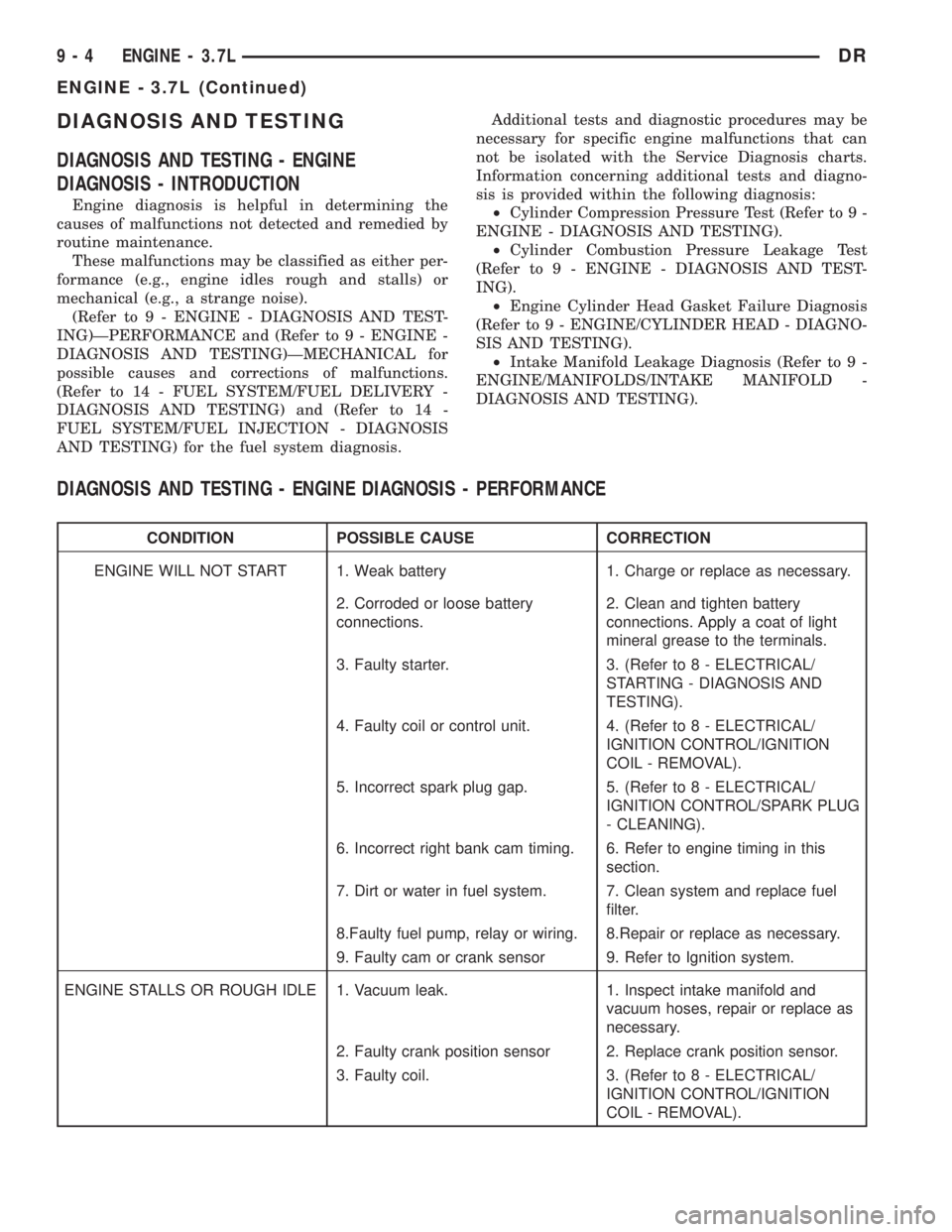
DIAGNOSIS AND TESTING - ENGINE DIAGNOSIS - PERFORMANCE
CONDITION POSSIBLE CAUSE CORRECTION
ENGINE WILL NOT START 1. Weak battery 1. Charge or replace as necessary.
2. Corroded or loose battery
connections.2. Clean and tighten battery
connections. Apply a coat of light
mineral grease to the terminals.
3. Faulty starter. 3. (Refer to 8 - ELECTRICAL/
STARTING - DIAGNOSIS AND
TESTING).
4. Faulty coil or control unit. 4. (Refer to 8 - ELECTRICAL/
IGNITION CONTROL/IGNITION
COIL - REMOVAL).
5. Incorrect spark plug gap. 5. (Refer to 8 - ELECTRICAL/
IGNITION CONTROL/SPARK PLUG
- CLEANING).
6. Incorrect right bank cam timing. 6. Refer to engine timing in this
section.
7. Dirt or water in fuel system. 7. Clean system and replace fuel
filter.
8.Faulty fuel pump, relay or wiring. 8.Repair or replace as necessary.
9. Faulty cam or crank sensor 9. Refer to Ignition system.
ENGINE STALLS OR ROUGH IDLE 1. Vacuum leak. 1. Inspect intake manifold and
vacuum hoses, repair or replace as
necessary.
2. Faulty crank position sensor 2. Replace crank position sensor.
3. Faulty coil. 3. (Refer to 8 - ELECTRICAL/
IGNITION CONTROL/IGNITION
COIL - REMOVAL).
9 - 4 ENGINE - 3.7LDR
ENGINE - 3.7L (Continued)
Page 1260 of 2895
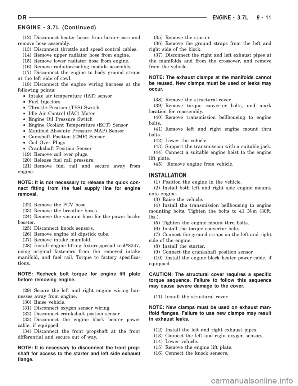
(12) Disconnect heater hoses from heater core and
remove hose assembly.
(13) Disconnect throttle and speed control cables.
(14) Remove upper radiator hose from engine.
(15) Remove lower radiator hose from engine.
(16) Remove radiator/cooling module assembly.
(17) Disconnect the engine to body ground straps
at the left side of cowl.
(18) Disconnect the engine wiring harness at the
following points:
²Intake air temperature (IAT) sensor
²Fuel Injectors
²Throttle Position (TPS) Switch
²Idle Air Control (IAC) Motor
²Engine Oil Pressure Switch
²Engine Coolant Temperature (ECT) Sensor
²Manifold Absolute Pressure MAP) Sensor
²Camshaft Position (CMP) Sensor
²Coil Over Plugs
²Crankshaft Position Sensor
(19) Remove coil over plugs.
(20) Release fuel rail pressure.
(21) Remove fuel rail and secure away from
engine.
NOTE: It is not necessary to release the quick con-
nect fitting from the fuel supply line for engine
removal.
(22) Remove the PCV hose.
(23) Remove the breather hoses.
(24) Remove the vacuum hose for the power brake
booster.
(25) Disconnect knock sensors.
(26) Remove engine oil dipstick tube.
(27) Remove intake manifold.
(28) Install engine lifting fixture,special tool#8247,
using original fasteners from the removed intake
manifold, and fuel rail. Torque to factory specifica-
tions.
NOTE: Recheck bolt torque for engine lift plate
before removing engine.
(29) Secure the left and right engine wiring har-
nesses away from engine.
(30) Raise vehicle.
(31) Disconnect oxygen sensor wiring.
(32) Disconnect crankshaft postion sensor.
(33) Disconnect the engine block heater power
cable, if equipped.
(34) Disconnect the front propshaft at the front
differential and secure out of way.
NOTE: It is necessary to disconnect the front prop-
shaft for access to the starter and left side exhaust
flange.(35) Remove the starter.
(36) Remove the ground straps from the left and
right side of the block.
(37) Disconnect the right and left exhaust pipes at
the manifolds and from the crossover, and remove
from the vehicle.
NOTE: The exhaust clamps at the manifolds cannot
be reused. New clamps must be used or leaks may
occur.
(38) Remove the structural cover.
(39) Remove torque convertor bolts, and mark
location for reassembly.
(40) Remove transmission bellhousing to engine
bolts.
(41) Remove left and right engine mount thru
bolts.
(42) Lower the vehicle.
(43) Support the transmission with a suitable jack.
(44) Connect a suitable engine hoist to the engine
lift plate.
(45) Remove engine from vehicle.
INSTALLATION
(1) Position the engine in the vehicle.
(2) Install both left and right side engine mounts
onto engine.
(3) Raise the vehicle.
(4) Install the transmission bellhousing to engine
mounting bolts. Tighten the bolts to 41 N´m (30ft.
lbs.).
(5) Tighten the engine mount thru bolts.
(6) Install the torque convertor bolts.
(7) Connect the ground straps on the left and right
side of the engine.
(8) Install the starter.
(9) Connect the crankshaft position sensor.
(10) Install the engine block heater power cable, if
equipped.
CAUTION: The structural cover requires a specific
torque sequence. Failure to follow this sequence
may cause severe damage to the cover.
(11) Install the structural cover.
NOTE: New clamps must be used on exhaust man-
ifold flanges. Failure to use new clamps may result
in exhaust leaks.
(12) Install the left and right exhaust pipes.
(13) Connect the left and right oxygen sensors.
(14) Lower vehicle.
(15) Remove the engine lift plate.
(16) Connect the knock sensors.
DRENGINE - 3.7L 9 - 11
ENGINE - 3.7L (Continued)
Page 1261 of 2895
(17) Connect the engine to body ground straps at
the left side of the cowl.
(18) Install the intake manifold.
(19) Install the engine oil dipstick tube.
(20) Install the power brake booster vacuum hose.
(21) Install the breather hoses.
(22) Install the PCV hose.
(23) Install the fuel rail.
(24) Install the coil over plugs.
(25) Connect the engine wiring harness at the fol-
lowing points:
²Intake air temperature (IAT) sensor
²Fuel Injectors
²Throttle Position (TPS) Switch
²Idle Air Control (IAC) Motor
²Engine Oil Pressure Switch
²Engine Coolant Temperature (ECT) Sensor
²Manifold Absolute Pressure MAP) Sensor
²Camshaft Position (CMP) Sensor
²Coil Over Plugs
²Crankshaft Position Sensor
(26) Reinstall the radiator/cooling module assem-
bly.
(27) Connect lower radiator hose.
(28) Connect upper radiator hose.
(29) Connect throttle and speed control cables.
(30) Install the heater hose assembly.
(31) Install coolant recovery bottle.
(32) Install the power steering pump.
(33) Install the generator.
(34) Install the A/C compressor.
(35) Install the drive belt.
(36) Install the fan shroud with the viscous fan
assembly.
(37) Install the radiator core support bracket.
(38) Install the air cleaner assembly.
(39) Refill the engine cooling system.
(40) Recharge the air conditioning.
(41) Install the hood.
(42) Check and fill engine oil.
(43) Connect the battery negative cable.
(44) Start the engine and check for leaks.SPECIFICATIONS
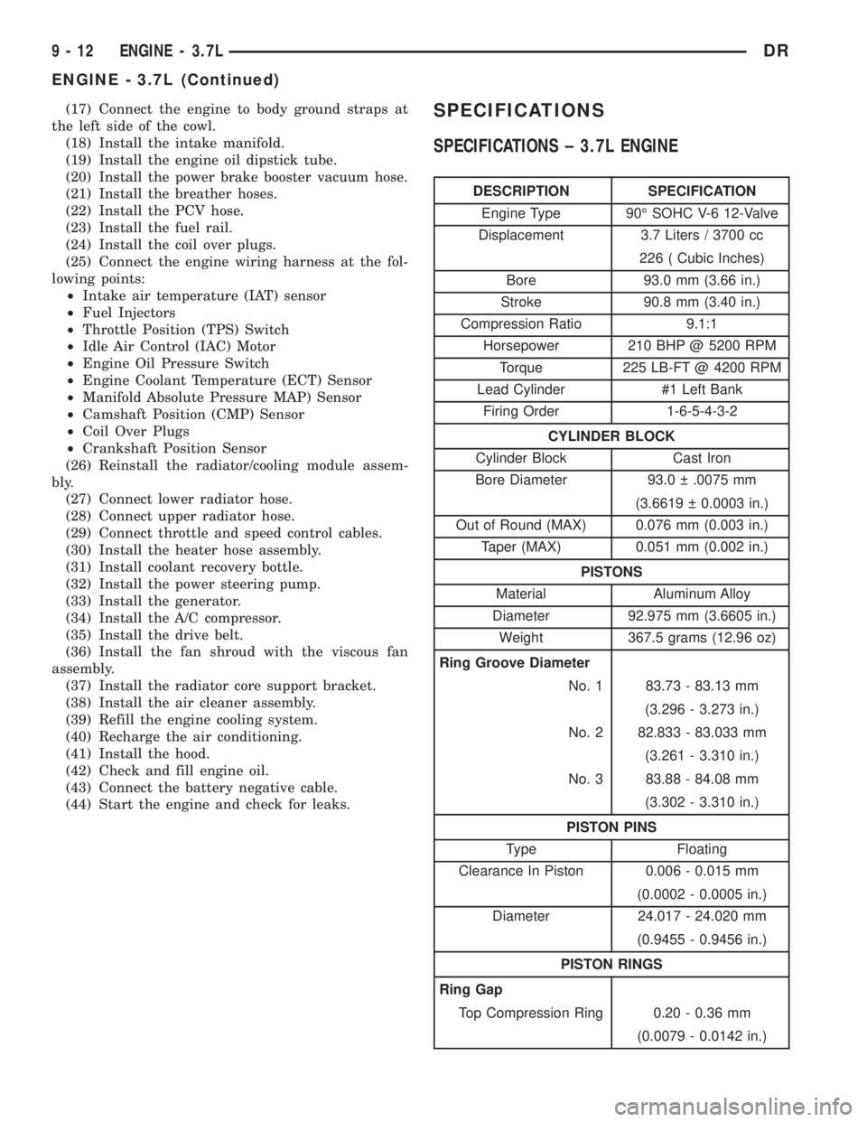
SPECIFICATIONS ± 3.7L ENGINE
DESCRIPTION SPECIFICATION
Engine Type 90É SOHC V-6 12-Valve
Displacement 3.7 Liters / 3700 cc
226 ( Cubic Inches)
Bore 93.0 mm (3.66 in.)
Stroke 90.8 mm (3.40 in.)
Compression Ratio 9.1:1
Horsepower 210 BHP @ 5200 RPM
Torque 225 LB-FT @ 4200 RPM
Lead Cylinder #1 Left Bank
Firing Order 1-6-5-4-3-2
CYLINDER BLOCK
Cylinder Block Cast Iron
Bore Diameter 93.0 .0075 mm
(3.6619 0.0003 in.)
Out of Round (MAX) 0.076 mm (0.003 in.)
Taper (MAX) 0.051 mm (0.002 in.)
PISTONS
Material Aluminum Alloy
Diameter 92.975 mm (3.6605 in.)
Weight 367.5 grams (12.96 oz)
Ring Groove Diameter
No. 1 83.73 - 83.13 mm
(3.296 - 3.273 in.)
No. 2 82.833 - 83.033 mm
(3.261 - 3.310 in.)
No. 3 83.88 - 84.08 mm
(3.302 - 3.310 in.)
PISTON PINS
Type Floating
Clearance In Piston 0.006 - 0.015 mm
(0.0002 - 0.0005 in.)
Diameter 24.017 - 24.020 mm
(0.9455 - 0.9456 in.)
PISTON RINGS
Ring Gap
Top Compression Ring 0.20 - 0.36 mm
(0.0079 - 0.0142 in.)
9 - 12 ENGINE - 3.7LDR
ENGINE - 3.7L (Continued)
Page 1264 of 2895
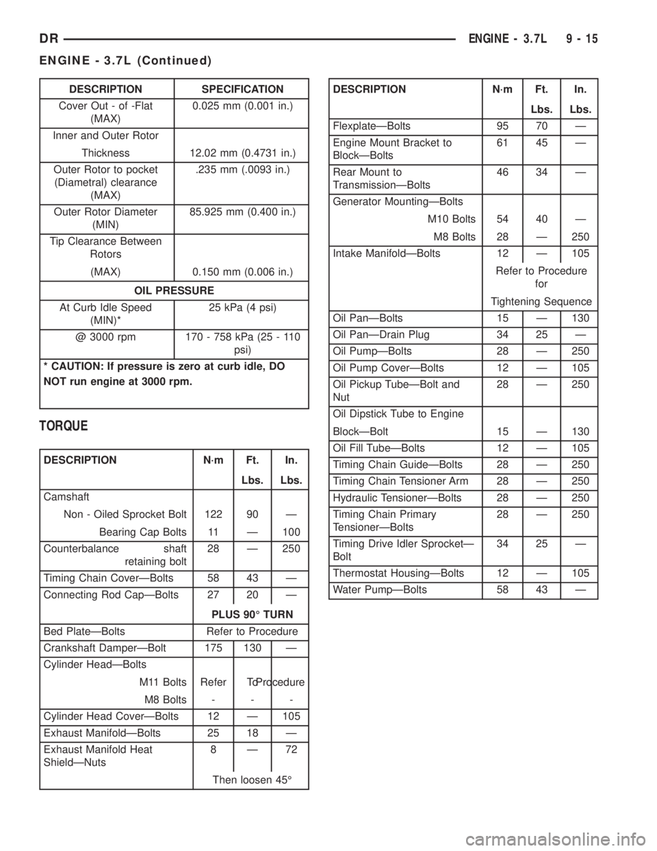
DESCRIPTION SPECIFICATION
Cover Out - of -Flat
(MAX)0.025 mm (0.001 in.)
Inner and Outer Rotor
Thickness 12.02 mm (0.4731 in.)
Outer Rotor to pocket
(Diametral) clearance
(MAX).235 mm (.0093 in.)
Outer Rotor Diameter
(MIN)85.925 mm (0.400 in.)
Tip Clearance Between
Rotors
(MAX) 0.150 mm (0.006 in.)
OIL PRESSURE
At Curb Idle Speed
(MIN)*25 kPa (4 psi)
@ 3000 rpm 170 - 758 kPa (25 - 110
psi)
* CAUTION: If pressure is zero at curb idle, DO
NOT run engine at 3000 rpm.
TORQUE
DESCRIPTION N´m Ft. In.
Lbs. Lbs.
Camshaft
Non - Oiled Sprocket Bolt 122 90 Ð
Bearing Cap Bolts 11 Ð 100
Counterbalance shaft
retaining bolt28 Ð 250
Timing Chain CoverÐBolts 58 43 Ð
Connecting Rod CapÐBolts 27 20 Ð
PLUS 90É TURN
Bed PlateÐBolts Refer to Procedure
Crankshaft DamperÐBolt 175 130 Ð
Cylinder HeadÐBolts
M11 Bolts Refer ToProcedure
M8 Bolts - - -
Cylinder Head CoverÐBolts 12 Ð 105
Exhaust ManifoldÐBolts 25 18 Ð
Exhaust Manifold Heat
ShieldÐNuts8Ð72
Then loosen 45É
DESCRIPTION N´m Ft. In.
Lbs. Lbs.
FlexplateÐBolts 95 70 Ð
Engine Mount Bracket to
BlockÐBolts61 45 Ð
Rear Mount to
TransmissionÐBolts46 34 Ð
Generator MountingÐBolts
M10 Bolts 54 40 Ð
M8 Bolts 28 Ð 250
Intake ManifoldÐBolts 12 Ð 105
Refer to Procedure
for
Tightening Sequence
Oil PanÐBolts 15 Ð 130
Oil PanÐDrain Plug 34 25 Ð
Oil PumpÐBolts 28 Ð 250
Oil Pump CoverÐBolts 12 Ð 105
Oil Pickup TubeÐBolt and
Nut28 Ð 250
Oil Dipstick Tube to Engine
BlockÐBolt 15 Ð 130
Oil Fill TubeÐBolts 12 Ð 105
Timing Chain GuideÐBolts 28 Ð 250
Timing Chain Tensioner Arm 28 Ð 250
Hydraulic TensionerÐBolts 28 Ð 250
Timing Chain Primary
TensionerÐBolts28 Ð 250
Timing Drive Idler SprocketÐ
Bolt34 25 Ð
Thermostat HousingÐBolts 12 Ð 105
Water PumpÐBolts 58 43 Ð
DRENGINE - 3.7L 9 - 15
ENGINE - 3.7L (Continued)