auxiliary battery DODGE RAM 2003 Service Repair Manual
[x] Cancel search | Manufacturer: DODGE, Model Year: 2003, Model line: RAM, Model: DODGE RAM 2003Pages: 2895, PDF Size: 83.15 MB
Page 361 of 2895

ers are supplied as standard equipment on diesel
engine powered models when equipped with an auto-
matic transmission.
The main water-to-oil transmission oil cooler is
mounted to a bracket on the intake side of the engine
(Fig. 4).
The air-to-oil cooler is located in front of and to the
left side of the radiator (Fig. 5).
OPERATION
The transmission oil is routed through the main
cooler first, then the auxiliary cooler where addi-
tional heat is removed from the transmission oil
before returning to the transmission. The cooler has
an internal thermostat that controls fluid flow
through the cooler. When the transmission fluid is
cold (less then operating temperature), the fluid is
routed through the cooler bypass. When the trans-
mission fluid reaches operating temperatures and
above, the thermostat closes off the bypass allowing
fluid flow through the cooler. The thermostat is ser-
vicable.
REMOVAL
REMOVALÐAIR TO OIL COOLER
(1) Remove Charge Air Cooler (Refer to 11 -
EXHAUST SYSTEM/TURBOCHARGER SYSTEM/
CHARGE AIR COOLER AND PLUMBING -
REMOVAL).(2) Place a drain pan under the oil cooler.
(3) Raise the vehicle.
(4) Disconnect the oil cooler quick-connect fittings
from the transmission lines.
(5) Remove the charge air cooler-to-oil cooler bolt
(Fig. 6).
(6) Remove two mounting nuts.
(7) Remove the oil cooler and line assembly
towards the front of vehicle. Cooler must be rotated
and tilted into position while removing.
REMOVALÐWATER TO OIL COOLER
CAUTION: If a leak should occur in the water-to-oil
cooler mounted to the side of the engine block,
engine coolant may become mixed with transmis-
sion fluid. Transmission fluid may also enter engine
cooling system. Both cooling system and transmis-
sion should be drained and inspected in case of oil
cooler leakage.
(1) Disconnect both battery negative cables.
(2) Remove starter (Refer to 8 - ELECTRICAL/
STARTING/STARTER MOTOR - REMOVAL).
(3) Drain cooling system (Refer to 7 - COOLING -
STANDARD PROCEDURE).
(4) Disconnect coolant lines from cooler.
Fig. 4 Transmission Water-To-Oil CoolerÐDiesel
EngineÐTypical
1 - TRANSMISSION WATER-TO-OIL COOLER
Fig. 5 Auxiliary Transmission Oil CoolerÐDiesel
Engine
1 - MOUNTING BOLTS
2 - RADIATOR
3 - QUICK-CONNECT FITTINGS
4 - TRANSMISSION OIL COOLER
7 - 74 TRANSMISSIONDR
TRANS COOLER - 5.9L DIESEL (Continued)
Page 362 of 2895
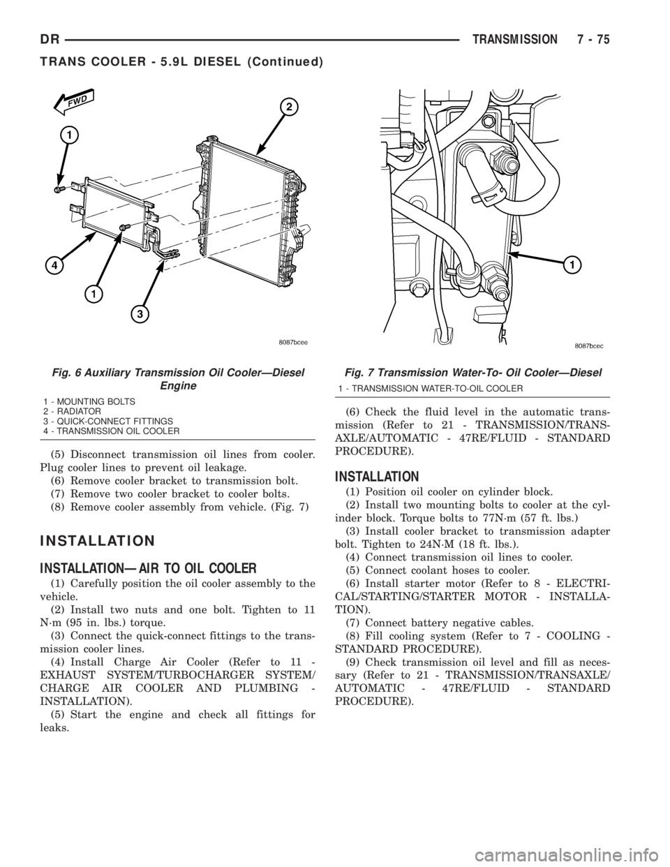
(5) Disconnect transmission oil lines from cooler.
Plug cooler lines to prevent oil leakage.
(6) Remove cooler bracket to transmission bolt.
(7) Remove two cooler bracket to cooler bolts.
(8) Remove cooler assembly from vehicle. (Fig. 7)
INSTALLATION
INSTALLATIONÐAIR TO OIL COOLER
(1) Carefully position the oil cooler assembly to the
vehicle.
(2) Install two nuts and one bolt. Tighten to 11
N´m (95 in. lbs.) torque.
(3) Connect the quick-connect fittings to the trans-
mission cooler lines.
(4) Install Charge Air Cooler (Refer to 11 -
EXHAUST SYSTEM/TURBOCHARGER SYSTEM/
CHARGE AIR COOLER AND PLUMBING -
INSTALLATION).
(5) Start the engine and check all fittings for
leaks.(6) Check the fluid level in the automatic trans-
mission (Refer to 21 - TRANSMISSION/TRANS-
AXLE/AUTOMATIC - 47RE/FLUID - STANDARD
PROCEDURE).
INSTALLATION
(1) Position oil cooler on cylinder block.
(2) Install two mounting bolts to cooler at the cyl-
inder block. Torque bolts to 77N´m (57 ft. lbs.)
(3) Install cooler bracket to transmission adapter
bolt. Tighten to 24N´M (18 ft. lbs.).
(4) Connect transmission oil lines to cooler.
(5) Connect coolant hoses to cooler.
(6) Install starter motor (Refer to 8 - ELECTRI-
CAL/STARTING/STARTER MOTOR - INSTALLA-
TION).
(7) Connect battery negative cables.
(8) Fill cooling system (Refer to 7 - COOLING -
STANDARD PROCEDURE).
(9) Check transmission oil level and fill as neces-
sary (Refer to 21 - TRANSMISSION/TRANSAXLE/
AUTOMATIC - 47RE/FLUID - STANDARD
PROCEDURE).
Fig. 6 Auxiliary Transmission Oil CoolerÐDiesel
Engine
1 - MOUNTING BOLTS
2 - RADIATOR
3 - QUICK-CONNECT FITTINGS
4 - TRANSMISSION OIL COOLER
Fig. 7 Transmission Water-To- Oil CoolerÐDiesel
1 - TRANSMISSION WATER-TO-OIL COOLER
DRTRANSMISSION 7 - 75
TRANS COOLER - 5.9L DIESEL (Continued)
Page 720 of 2895
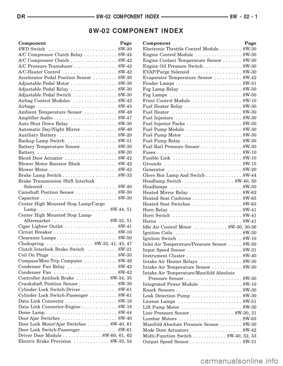
8W-02 COMPONENT INDEX
Component Page
4WD Switch......................... 8W-30
A/C Compressor Clutch Relay............ 8W-42
A/C Compressor Clutch................. 8W-42
A/C Pressure Transducer................ 8W-42
A/C-Heater Control.................... 8W-42
Accelerator Pedal Position Sensor......... 8W-30
Adjustable Pedal Motor................. 8W-30
Adjustable Pedal Relay................. 8W-30
Adjustable Pedal Switch................ 8W-30
Airbag Control Modules................ 8W-43
Airbags............................. 8W-43
Ambient Temperature Sensor............ 8W-49
Amplifier Audio....................... 8W-47
Auto Shut Down Relay................. 8W-30
Automatic Day/Night Mirror............. 8W-49
Auxiliary Battery..................... 8W-20
Backup Lamp Switch.................. 8W-51
Battery Temperature Sensor............. 8W-30
Battery............................. 8W-20
Blend Door Actuator................... 8W-42
Blower Motor Resistor Block............. 8W-42
Blower Motor......................... 8W-42
Brake Lamp Switch.................... 8W-33
Brake Transmission Shift Interlock
Solenoid........................... 8W-40
Camshaft Position Sensor............... 8W-30
Capacitor............................ 8W-30
Center High Mounted Stop Lamp/Cargo
Lamp.......................... 8W-44, 51
Center High Mounted Stop Lamp-
Aftermarket..................... 8W-33, 51
Cigar Lighter Outlet................... 8W-41
Circuit Breaker....................... 8W-10
Clearance Lamps...................... 8W-50
Clockspring................. 8W-33, 41, 43, 47
Clutch Interlock Brake Switch........... 8W-21
Coil On Plugs........................ 8W-30
Compass/Mini-Trip Computer............ 8W-49
Condenser Fan Relay.................. 8W-42
Condenser Fan....................... 8W-42
Controller Antilock Brake............ 8W-34, 35
Crankshaft Position Sensor.............. 8W-30
Cylinder Lock Switch-Driver............. 8W-61
Cylinder Lock Switch-Passenger.......... 8W-61
Data Link Connector................... 8W-18
Data Link Connector-Engine............. 8W-18
Dome Lamp.......................... 8W-44
Door Ajar Switches.................... 8W-40
Door Lock Motor/Ajar Switches........ 8W-40, 61
Door Lock Switch-Passenger............. 8W-61
Driver Door Module.............. 8W-60, 61, 62
Electric Brake Provision............. 8W-33, 54Component Page
Electronic Throttle Control Module........ 8W-30
Engine Control Module................. 8W-30
Engine Coolant Temperature Sensor....... 8W-30
Engine Oil Pressure Switch.............. 8W-30
EVAP/Purge Solenoid.................. 8W-30
Evaporator Temperature Sensor.......... 8W-42
Fender Lamps........................ 8W-51
Fog Lamp Relay...................... 8W-50
Fog Lamps.......................... 8W-50
Front Control Module.................. 8W-10
Fuel Heater Relay..................... 8W-30
Fuel Heater.......................... 8W-30
Fuel Injectors........................ 8W-30
Fuel Injector Packs.................... 8W-30
Fuel Pump Module.................... 8W-30
Fuel Pump Motor..................... 8W-30
Fuel Pump Relay...................... 8W-30
Fuel Rail Pressure Sensor............... 8W-30
Fuses............................... 8W-10
Fusible Link......................... 8W-10
Grounds............................ 8W-15
Generator........................... 8W-20
Glove Box Lamp And Switch............. 8W-44
Headlamp Switch.................. 8W-40, 50
Headlamps.......................... 8W-50
Heated Mirror Relay................... 8W-62
Heated Seat Cushions.................. 8W-63
Heated Seat Switches.................. 8W-63
Horn Relay.......................... 8W-41
Horn Switch......................... 8W-41
Horns.............................. 8W-41
Idle Air Control Motor............ 8W-30, 30-36
Ignition Coils......................... 8W-30
Ignition Switch....................... 8W-10
Inlet Air Temperature/Pressure Sensor..... 8W-30
Input Speed Sensor.................... 8W-31
Instrument Cluster.................... 8W-40
Intake Air Heater Relays............... 8W-30
Intake Air Temperature Sensor........... 8W-30
Intake Air Temperature/Manifold Absolute
Pressure Sensor..................... 8W-30
Integrated Power Module............... 8W-10
Knock Sensors........................ 8W-30
Leak Detection Pump.................. 8W-30
License Lamps....................... 8W-51
Lift Pump Motor...................... 8W-30
Line Pressure Sensor................ 8W-30, 31
Lumbar Motors....................... 8W-63
Manifold Absolute Pressure Sensor........ 8W-30
Mode Door Actuators................... 8W-42
Multi-Function Switch............ 8W-40, 52, 53
Output Speed Sensor................... 8W-31
DR8W-02 COMPONENT INDEX 8W - 02 - 1
Page 722 of 2895
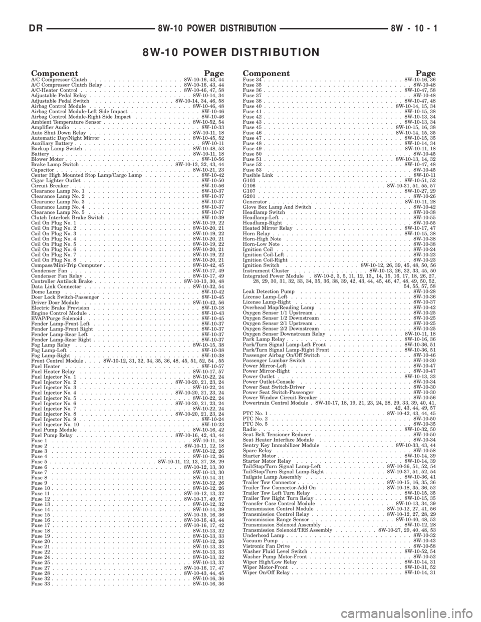
8W-10 POWER DISTRIBUTION
Component PageA/C Compressor Clutch....................8W-10-16, 43, 44
A/C Compressor Clutch Relay.................8W-10-16, 43, 44
A/C-Heater Control......................8W-10-46, 47, 58
Adjustable Pedal Relay......................8W-10-14, 34
Adjustable Pedal Switch.................8W-10-14, 34, 46, 58
Airbag Control Module......................8W-10-46, 48
Airbag Control Module-Left Side Impact...............8W-10-46
Airbag Control Module-Right Side Impact..............8W-10-46
Ambient Temperature Sensor...................8W-10-52, 54
Amplifier Audio...........................8W-10-33
Auto Shut Down Relay......................8W-10-11, 18
Automatic Day/Night Mirror...................8W-10-45, 52
Auxiliary Battery...........................8W-10-11
Backup Lamp Switch.......................8W-10-48, 53
Battery..............................8W-10-11, 18
Blower Motor.............................8W-10-56
Brake Lamp Switch....................8W-10-13, 32, 43, 44
Capacitor.............................8W-10-21, 23
Center High Mounted Stop Lamp/Cargo Lamp............8W-10-42
Cigar Lighter Outlet.........................8W-10-50
Circuit Breaker............................8W-10-56
Clearance Lamp No. 1........................8W-10-37
Clearance Lamp No. 2........................8W-10-37
Clearance Lamp No. 3........................8W-10-37
Clearance Lamp No. 4........................8W-10-37
Clearance Lamp No. 5........................8W-10-37
Clutch Interlock Brake Switch....................8W-10-39
Coil On Plug No. 1........................8W-10-19, 22
Coil On Plug No. 2........................8W-10-20, 21
Coil On Plug No. 3........................8W-10-19, 22
Coil On Plug No. 4........................8W-10-20, 21
Coil On Plug No. 5........................8W-10-19, 22
Coil On Plug No. 6........................8W-10-20, 21
Coil On Plug No. 7........................8W-10-19, 22
Coil On Plug No. 8........................8W-10-20, 21
Compass/Mini-Trip Computer...................8W-10-42, 45
Condenser Fan..........................8W-10-17, 49
Condenser Fan Relay.......................8W-10-17, 49
Controller Antilock Brake...................8W-10-13, 30, 48
Data Link Connector.......................8W-10-32, 54
Dome Lamp.............................8W-10-42
Door Lock Switch-Passenger.....................8W-10-45
Driver Door Module.......................8W-10-42, 56
Electric Brake Provision.......................8W-10-18
Engine Control Module........................8W-10-43
EVAP/Purge Solenoid.........................8W-10-45
Fender Lamp-Front Left.......................8W-10-37
Fender Lamp-Front Right......................8W-10-37
Fender Lamp-Rear Left.......................8W-10-37
Fender Lamp-Rear Right.......................8W-10-37
Fog Lamp Relay.........................8W-10-15, 38
Fog Lamp-Left............................8W-10-38
Fog Lamp-Right...........................8W-10-38
Front Control Module....8W-10-12, 31, 32, 34, 35, 36, 48, 45, 51, 52, 54 , 55
Fuel Heater.............................8W-10-57
Fuel Heater Relay........................8W-10-17, 57
Fuel Injector No. 1........................8W-10-22, 24
Fuel Injector No. 2....................8W-10-20, 21, 23, 24
Fuel Injector No. 3........................8W-10-22, 24
Fuel Injector No. 4....................8W-10-20, 21, 23, 24
Fuel Injector No. 5........................8W-10-22, 24
Fuel Injector No. 6....................8W-10-20, 21, 23, 24
Fuel Injector No. 7........................8W-10-22, 24
Fuel Injector No. 8....................8W-10-20, 21, 23, 24
Fuel Injector No. 9..........................8W-10-24
Fuel Injector No. 10.........................8W-10-23
Fuel Pump Module........................8W-10-16, 42
Fuel Pump Relay.....................8W-10-16, 42, 43, 44
Fuse 1..............................8W-10-11, 18
Fuse 2............................8W-10-11, 12, 18
Fuse 3..............................8W-10-12, 26
Fuse 4..............................8W-10-12, 26
Fuse 5.......................8W-10-11, 12, 13, 27, 28, 29
Fuse 6............................8W-10-12, 13, 30
Fuse 7..............................8W-10-13, 30
Fuse 8..............................8W-10-14, 31
Fuse 9..............................8W-10-12, 26
Fuse 10..............................8W-10-12, 26
Fuse 11............................8W-10-12, 13, 32
Fuse 12............................8W-10-17, 49, 57
Fuse 13..............................8W-10-12, 32
Fuse 14..............................8W-10-14, 39
Fuse 15............................8W-10-15, 16, 36
Fuse 16............................8W-10-16, 43, 44
Fuse 17............................8W-10-16, 17, 42
Fuse 18..............................8W-10-13, 32
Fuse 19..............................8W-10-13, 33
Fuse 20..............................8W-10-12, 26
Fuse 21..............................8W-10-13, 33
Fuse 22..............................8W-10-13, 33
Fuse 24..............................8W-10-13, 32
Fuse 25..............................8W-10-13, 33
Fuse 27............................8W-10-16, 17, 47
Fuse 28............................8W-10-43, 44, 45
Fuse 32..............................8W-10-16, 36
Fuse 33..............................8W-10-16, 36Component PageFuse 34..............................8W-10-16, 36
Fuse 35...............................8W-10-48
Fuse 36..............................8W-10-47, 58
Fuse 37...............................8W-10-48
Fuse 38..............................8W-10-47, 48
Fuse 40............................8W-10-14, 15, 34
Fuse 41..............................8W-10-15, 38
Fuse 42..............................8W-10-13, 34
Fuse 43..............................8W-10-13, 34
Fuse 45............................8W-10-15, 16, 38
Fuse 46............................8W-10-14, 15, 35
Fuse 47..............................8W-10-15, 35
Fuse 48..............................8W-10-14, 34
Fuse 49..............................8W-10-11, 18
Fuse 50...............................8W-10-45
Fuse 51............................8W-10-13, 14, 32
Fuse 52..............................8W-10-47, 48
Fuse 53...............................8W-10-45
Fusible Link.............................8W-10-11
G103...............................8W-10-51, 52
G106...........................8W-10-31, 51, 55, 57
G107...............................8W-10-27, 29
G201.................................8W-10-26
Generator.............................8W-10-11, 28
Glove Box Lamp And Switch.....................8W-10-42
Headlamp Switch..........................8W-10-38
Headlamp-Left............................8W-10-55
Headlamp-Right...........................8W-10-55
Heated Mirror Relay.......................8W-10-17, 47
Horn Relay............................8W-10-15, 38
Horn-High Note...........................8W-10-38
Horn-Low Note............................8W-10-38
Ignition Coil.............................8W-10-24
Ignition Coil-Left...........................8W-10-23
Ignition Coil-Right..........................8W-10-23
Ignition Switch................8W-10-12, 26, 39, 45, 48, 50, 56
Instrument Cluster................8W-10-13, 26, 32, 33, 45, 50
Integrated Power Module . 8W-10-2, 3, 5, 11, 12, 13,, 14, 15, 16, 17, 18, 26, 27,
28, 29, 30, 31, 32, 33, 34, 35, 36, 38, 39, 42, 43, 44, 45, 46, 47, 48, 49, 50, 52,
54, 55, 57, 58
Leak Detection Pump........................8W-10-28
License Lamp-Left..........................8W-10-36
License Lamp-Right.........................8W-10-37
Overhead Map/Reading Lamp....................8W-10-42
Oxygen Sensor 1/1 Upstream.....................8W-10-25
Oxygen Sensor 1/2 Downstream...................8W-10-25
Oxygen Sensor 2/1 Upstream.....................8W-10-25
Oxygen Sensor 2/2 Downstream...................8W-10-25
Oxygen Sensor Downstream Relay................8W-10-11, 18
Park Lamp Relay.........................8W-10-16, 36
Park/Turn Signal Lamp-Left Front................8W-10-36, 51
Park/Turn Signal Lamp-Right Front...............8W-10-36, 51
Passenger Airbag On/Off Switch...................8W-10-46
Passenger Lumbar Switch......................8W-10-30
Power Mirror-Left..........................8W-10-47
Power Mirror-Right.........................8W-10-47
Power Outlet...........................8W-10-13, 33
Power Outlet-Console........................8W-10-34
Power Seat Switch-Driver......................8W-10-30
Power Seat Switch-Passenger....................8W-10-30
Power Window Circuit Breaker....................8W-10-56
Powertrain Control Module . 8W-10-17, 18, 19, 21, 23, 24, 28, 29, 33, 39, 40, 41,
42, 43, 44, 49, 57
PTCNo.1.........................8W-10-42, 43, 44, 45
PTCNo.2 ..............................8W-10-50
PTCNo.5 ..............................8W-10-35
Radio...............................8W-10-32, 50
Seat Belt Tensioner Reducer.....................8W-10-50
Seat Heater Interface Module....................8W-10-34
Sentry Key Immobilizer Module...............8W-10-33, 43, 44
Spare Relay.............................8W-10-58
Starter Motor...........................8W-10-14, 39
Starter Motor Relay.......................8W-10-14, 39
Tail/Stop/Turn Signal Lamp-Left.............8W-10-36, 51, 52, 54
Tail/Stop/Turn Signal Lamp-Right.............8W-10-37, 51, 52, 54
Tailgate Lamp Assembly.....................8W-10-36, 41
Trailer Tow Connector...................8W-10-15, 16, 35, 36
Trailer Tow Connector-Add On..............8W-10-18, 35, 36, 52
Trailer Tow Left Turn Relay...................8W-10-15, 35
Trailer Tow Right Turn Relay...................8W-10-15, 35
Transfer Case Control Module................8W-10-13, 34, 39
Transmission Control Module...............8W-10-12, 27, 41, 56
Transmission Control Relay................8W-10-12, 27, 28, 29
Transmission Range Sensor..................8W-10-40, 48, 53
Transmission Solenoid Assembly.................8W-10-12, 28
Transmission Solenoid/TRS Assembly.........8W-10-27, 29, 40, 48, 53
Underhood Lamp...........................8W-10-32
Vacuum Pump............................8W-10-43
Vistronic Fan Drive.........................8W-10-58
Washer Fluid Level Switch....................8W-10-52, 54
Washer Pump Motor-Front......................8W-10-52
Wiper High/Low Relay......................8W-10-14, 31
Wiper Motor-Front........................8W-10-31, 52
Wiper On/Off Relay........................8W-10-14, 31
DR8W-10 POWER DISTRIBUTION 8W - 10 - 1
Page 780 of 2895
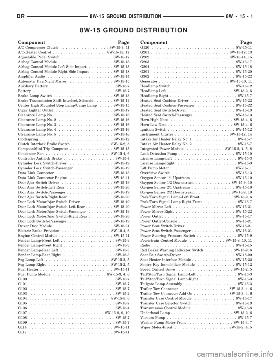
8W-15 GROUND DISTRIBUTION
Component Page
A/C Compressor Clutch..................8W-15-9, 11
A/C-Heater Control....................8W-15-15, 17
Adjustable Pedal Switch...................8W-15-17
Airbag Control Module....................8W-15-18
Airbag Control Module-Left Side Impact.........8W-15-18
Airbag Control Module-Right Side Impact........8W-15-18
Amplifier Audio........................8W-15-14
Automatic Day/Night Mirror................8W-15-15
Auxiliary Battery........................8W-15-7
Battery..............................8W-15-7
Brake Lamp Switch......................8W-15-13
Brake Transmission Shift Interlock Solenoid.......8W-15-14
Center High Mounted Stop Lamp/Cargo Lamp.....8W-15-15
Cigar Lighter Outlet.....................8W-15-17
Clearance Lamp No. 1....................8W-15-16
Clearance Lamp No. 2....................8W-15-16
Clearance Lamp No. 3....................8W-15-16
Clearance Lamp No. 4....................8W-15-16
Clearance Lamp No. 5....................8W-15-16
Clockspring...........................8W-15-12
Clutch Interlock Brake Switch..............8W-15-2, 5
Compass/Mini-Trip Computer................8W-15-15
Condenser Fan........................8W-15-4, 6
Controller Antilock Brake...................8W-15-4
Cylinder Lock Switch-Driver................8W-15-19
Cylinder Lock Switch-Passenger..............8W-15-19
Data Link Connector.....................8W-15-13
Data Link Connector-Engine................8W-15-11
Door Ajar Switch-Driver...................8W-15-19
Door Ajar Switch-Left Rear.................8W-15-20
Door Ajar Switch-Passenger.................8W-15-19
Door Ajar Switch-Right Rear................8W-15-20
Door Lock Motor/Ajar Switch-Driver............8W-15-19
Door Lock Motor/Ajar Switch-Left Rear..........8W-15-20
Door Lock Motor/Ajar Switch-Passenger.........8W-15-19
Door Lock Motor/Ajar Switch-Right Rear.........8W-15-20
Door Lock Switch-Passenger.................8W-15-19
Driver Door Module......................8W-15-21
Electric Brake Provision..................8W-15-4, 6
Engine Control Module....................8W-15-11
Fender Lamp-Front Left....................8W-15-3
Fender Lamp-Front Right...................8W-15-3
Fender Lamp-Rear Left....................8W-15-3
Fender Lamp-Rear Right...................8W-15-3
Fog Lamp-Left........................8W-15-2, 5
Fog Lamp-Right.......................8W-15-2, 5
Fuel Heater...........................8W-15-11
Fuel Pump Module....................8W-15-3, 4, 6
G100................................8W-15-7
G101................................8W-15-7
G102................................8W-15-7
G103................................8W-15-2
G104..............................8W-15-5, 6
G105................................8W-15-7
G106................................8W-15-4
G107............................8W-15-8, 9, 10
G108................................8W-15-7
G109................................8W-15-7
G114 ...............................8W-15-11
G117 ...............................8W-15-11
Component Page
G120...............................8W-15-11
G201.............................8W-15-12, 13
G202.............................8W-15-14, 15
G203...............................8W-15-17
G204...............................8W-15-18
G301...............................8W-15-20
G302...............................8W-15-22
Generator..........................8W-15-10, 11
Headlamp Switch.......................8W-15-12
Headlamp-Left........................8W-15-2, 5
Headlamp-Right.........................8W-15-7
Heated Seat Cushion-Driver.................8W-15-22
Heated Seat Cushion-Passenger..............8W-15-22
Heated Seat Switch-Driver.................8W-15-13
Heated Seat Switch-Passenger...............8W-15-13
Horn-High Note.......................8W-15-4, 6
Horn-Low Note........................8W-15-4, 6
Ignition Switch.........................8W-15-12
Instrument Cluster....................8W-15-12, 14
Intake Air Heater Relay No. 1................8W-15-7
Intake Air Heater Relay No. 2................8W-15-7
Integrated Power Module..............8W-15-2, 4, 5, 8
Leak Detection Pump.....................8W-15-10
License Lamp-Left.......................8W-15-3
License Lamp-Right......................8W-15-3
Lift Pump Motor........................8W-15-11
Overdrive Switch.......................8W-15-13
Oxygen Sensor 1/1 Upstream................8W-15-10
Oxygen Sensor 1/2 Downstream.............8W-15-9, 10
Oxygen Sensor 2/1 Upstream................8W-15-10
Oxygen Sensor 2/2 Downstream.............8W-15-9, 10
Park/Turn Signal Lamp-Left Front............8W-15-2, 6
Park/Turn Signal Lamp-Right Front............8W-15-7
Power Mirror-Left.......................8W-15-21
Power Mirror-Right......................8W-15-22
Power Outlet..........................8W-15-17
Power Outlet-Console.....................8W-15-21
Power Seat Switch-Driver..................8W-15-21
Power Seat Switch-Passenger................8W-15-21
Power Steering Pressure Switch...............8W-15-9
Powertrain Control Module.............8W-15-8, 10, 11
Radio...............................8W-15-15
Red Brake Warning Indicator Switch..........8W-15-2, 6
Seat Belt Switch-Driver...................8W-15-20
Seat Heater Interface Module................8W-15-22
Sentry Key Immobilizer Module..............8W-15-12
Speed Control Servo.....................8W-15-2, 5
Tail/Stop/Turn Signal Lamp-Left...............8W-15-3
Tail/Stop/Turn Signal Lamp-Right..............8W-15-3
Tailgate Lamp Assembly....................8W-15-3
Trailer Tow Connector..................8W-15-3, 4, 6
Trailer Tow Connector-Add On.............8W-15-3, 4, 6
Transfer Case Control Module...............8W-15-17
Transfer Case Selector Switch................8W-15-13
Transmission Control Module.................8W-15-8
Underhood Lamp.......................8W-15-2, 6
Vacuum Pump..........................8W-15-7
Washer Pump Motor-Front.................8W-15-4, 7
Wiper Motor-Front....................8W-15-2, 4, 5
DR8W-15 GROUND DISTRIBUTION 8W - 15 - 1
Page 808 of 2895
8W-20 CHARGING SYSTEM
Component Page
Auxiliary Battery.................... 8W-20-3
Battery.......................... 8W-20-2, 3
Engine Control Module.............. 8W-20-3, 4
Fuse 19.......................... 8W-20-2, 3
Fusible Link.................... 8W-20-2, 3, 4
G100............................ 8W-20-2, 3
G101............................ 8W-20-2, 3
G102............................ 8W-20-2, 3
G107.............................. 8W-20-2
G108.............................. 8W-20-3Component Page
G109.............................. 8W-20-3
G120.............................. 8W-20-3
Generator........................ 8W-20-2, 3
Integrated Power Module.......... 8W-20-2, 3, 4
Leak Detection Pump................. 8W-20-2
Powertrain Control Module.......... 8W-20-2, 3
Starter Motor..................... 8W-20-2, 3
Transmission Control Relay............ 8W-20-2
DR8W-20 CHARGING SYSTEM 8W - 20 - 1
Page 812 of 2895
8W-21 STARTING SYSTEM
Component Page
Auxiliary Battery.................... 8W-21-3
Battery.......................... 8W-21-2, 3
Clutch Interlock Brake Switch.......... 8W-21-4
Fuse 14.......................... 8W-21-2, 3
G103.............................. 8W-21-4
G104.............................. 8W-21-4
Ignition Switch.................... 8W-21-2, 3
Integrated Power Module.......... 8W-21-2, 3, 4Component Page
Powertrain Control Module.......... 8W-21-2, 4
Starter Motor..................... 8W-21-2, 3
Starter Motor Relay................ 8W-21-2, 3
Transfer Case Control Module.......... 8W-21-4
Transmission Range Sensor............ 8W-21-4
Transmission Solenoid/TRS Assembly.... 8W-21-4
DR8W-21 STARTING SYSTEM 8W - 21 - 1
Page 1541 of 2895
(2) Lower engine into the engine compartment and
install the engine the engine mount through bolts
and nuts.
(3) Tighten the mount through bolts and nuts to
88 N-m (65 ft-lbs) torque.
(4) Remove the engine lifting device (Tool 9009).
(5) Check cylinder head capscrew length and
install into cylinder head.
(6) Torque alternately to 70 N-m (52 ft-lbs). Torque
alternately to 105 N-m (77 ft-lbs). Rotate 90 degrees.
(7) Install rocker housing. Torque to 24 N-m (18 ft-
lbs). Refer to Section 9 Rocker Housing Installation
(8) Replace injector o-ring and sealing washer on
injectors #5 and #6. Install injectors and alternately
tighten hold-down capscrews to 10 N-m (89 in-lbs).
(9) Install fuel connector tube and fuel connector
tube nut. Torque to 50 N-m (37 ft-lb). 10.
(10) Install #5 and #6 high pressure fuel lines. Fol-
low correct torque sequence per section 14. Torque
fuel line fittings to 30 N-m (22 ft-lb). Torque brace
capscrew to 24 N-m (18 ft-lb).
(11) Install rear engine lift bracket. Torque to 77
N-m (57 ft-lb).
(12) Install push tubes, rocker arms, and pedestals
for cylinders #4, #5, and #6. Torque the mounting
bolts to 36 N-m (27 ft-lbs).
(13) Reset valve lash on cylinders #4, #5, and #6.
Torque adjusting nuts to 24 N-m (18 ft-lbs).
(14) Install cylinder head cover. Torque to 24 N-m
(18 ft-lbs).(Refer to 9 - ENGINE/CYLINDER HEAD -
INSTALLATION).
(15) Connect breather tube and lube oil drain tube
to breather housing. Install breather housing. Torque
capscrews to 24 N-m (18 ft-lbs)
(16) Connect fuel supply and return hoses.
(17) Connect ECM ground to hydroform screw.
Connect ECM power connector.
(18) Install the APPS cable(s) to the APPS. Install
the throttle linkage cover.
(19) Install the power steering pump.
(20) Install the damper and speed indicator ring.
Torque to 40 N-m (30 ft-lb) plus 60 degrees.
(21) Connect the engine block heater connection.
(22) Connect the A/C compressor and pressure sen-
sor connectors
(23) Install the charge air cooler and a/c condenser
(if equipped). Install and tighten the charge air
cooler mounting bolts to 2 N-m (17 in-lbs).
(24) Connect the charge air cooler piping. Torque
all clamps to 8 N-m (72 in-lbs).
(25) Connect the a/c refrigerant lines to the a/c
condenser (if equipped).
(26) Install the radiator upper support panel.
(27) Install radiator.
(28) Connect the transmission quick-connect oil
cooler lines.(29) Raise vehicle.
(30) Connect a/c compressor suction/discharge hose
(if equipped).
(31) Install the radiator lower hose and clamps.
(32) Install the battery negative cables to the
engine block on the driver and passenger side.
(33) Install the transmission adapter with a new
camshaft rectangular ring seal. Torque to 77 N-m (57
ft-lb).
(34) Install the flywheel/flexplate. Torque to 137
N-m (101 ft-lb).
(35) Install the starter motor. Torque to 43 N-m
(32 ft-lb). (Refer to 8 - ELECTRICAL/STARTING/
STARTER MOTOR - INSTALLATION).
(36) Connect engine to vehicle harness connectors.
(37) Install transmission and transfer case (if
equipped).
(38) Connect the exhaust pipe to the turbocharger
elbow.
(39) Connect the transmission auxiliary oil cooler
lines (if equipped).
(40) Lower the vehicle.
(41)
Connect the heater core supply and return hoses.
(42) Install the cooling fan and upper fan shroud
at the same time. (Refer to 7 - COOLING/ENGINE/
RADIATOR FAN - INSTALLATION).
(43) Install the coolant recovery bottle.
(44) Install the windshield washer bottle.
(45) Install the upper radiator hose and clamps.
(46) Raise vehicle.
(47) Connect electronically controlled fan drive
wire harness. Install lower radiator fan shroud.
(48) Change oil filter and install new engine oil.
(49) Fill the cooling system with coolant. (Refer to
7 - COOLING - STANDARD PROCEDURE).
(50) Connect grid heater harness at grid heater
relays.
(51) Connect electrical connections to rear of alter-
nator.
(52) Start the engine and inspect for engine oil,
coolant, and fuel leaks.
INSTALLATIONÐCRANKCASE BREATHER
(1) Install a new o-ring onto the breather element.
(2) Lubricate o-ring and install into cylinder head
cover. Torque capscrews to 10 N´m (89 in. lbs.).
(3) Connect breather tube and lube oil drain tube.
(4) Install breather cover (Fig. 4). Torque to 24
N´m (18 ft. lbs.)
(5) Install oil fill cap.
9 - 292 ENGINE 5.9L DIESELDR
ENGINE 5.9L DIESEL (Continued)
Page 1570 of 2895
(14) Install the fan support/hub assembly and
tighten bolts to 33 N´m (24 ft. lbs.) torque.
(15) Install the power steering pump.
(16) Install accessory drive belt tensioner. Torque
bolt to 43 Nm (43 ft. lbs.).
(17) Install the accessory drive belt (Refer to 7 -
COOLING/ACCESSORY DRIVE/DRIVE BELTS -
INSTALLATION).
(18) Install the charge air cooler (with a/c con-
denser and auxiliary transmission oil cooler, if
equipped) and tighten the mounting bolts to 2 N´m
(17 in. lbs.) torque.
(19) Connect charge air cooler inlet and outlet
pipes. Tighten clamps to 11 N´m (95 in. lbs.) torque.
(20) Install the radiator upper support panel.
(21) Close radiator petcock and lower the radiator
into the engine compartment. Tighten the mounting
bolts to 11 N´m (95 in. lbs.) torque.
(22) Raise vehicle on hoist.
(23)
Connect radiator lower hose and install clamp.
(24) Connect transmission auxiliary oil cooler lines
(if equipped).
(25) Lower vehicle.
(26) Install the fan shroud and tighten the mount-
ing screws to 6 N´m (50 in. lbs.) torque.
(27) Install the electronically controlled viscous
fan/drive assembly. Connect harness connector.(Refer
to 7 - COOLING/ENGINE/RADIATOR FAN -
INSTALLATION).
(28) Install the coolant recovery and windshield
washer fluid reservoirs to the fan shroud.
(29) Connect the coolant recovery hose to the radi-
ator filler neck.
(30) Add engine coolant (Refer to 7 - COOLING -
STANDARD PROCEDURE).
(31) Charge A/C system with refrigerant (if A/C
equipped) (Refer to 24 - HEATING & AIR CONDI-
TIONING/PLUMBING - STANDARD PROCEDURE).
(32) Connect the battery negative cables.
(33) Start engine and check for engine oil and cool-
ant leaks.
CONNECTING ROD BEARINGS
STANDARD PROCEDURE - CONNECTING ROD
BEARING AND CRANKSHAFT JOURNAL
CLEARANCE
(1) Measure the connecting rod bore with bearings
removedand the bolts tightened to 100 N´m (73 ft.
lbs.) torque..
(2) Measure the connecting rod bore with the bear-
ingsinstalledand the bolts tightened to 100 N´m
(73 ft. lbs.) torque.
Measure within 20É arc from each side of the part-
ing line. Also measure 90É from parting line.Record the smallest and largest diameter.
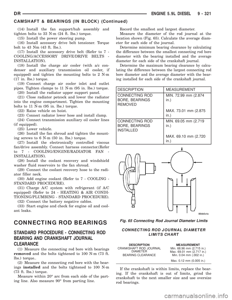
Measure the diameter of the rod journal at the
location shown (Fig. 65). Calculate the average diam-
eter for each side of the journal.
Determine minimum bearing clearance by calculating
the differance between the smallest connecting rod bore
diameter with the bearing installed and the average
diameter for each side of the crankshaft journal.
Determine the maximum bearing clearance by calcu-
lating the difference between the largest connecting rod
bore diameter and the average diameter with the bear-
ing installed for each side of the crankshaft journal.
DESCRIPTION MEASUREMENT
CONNECTING ROD
BORE, BEARINGS
REMOVEDMIN. 72.99 mm (2.874
in.)
MAX. 73.01 mm (2.875
in.)
CONNECTING ROD
BORE, BEARINGS
INSTALLEDMIN. 69.05 mm (2.719
in.)
MAX. 69.10 mm (2.720
in.)
If the crankshaft is within limits, replace the bear-
ing. If the crankshaft is out of limits, grind the
crankshaft to the next smaller size and use oversize
rod bearings.
Fig. 65 Connecting Rod Journal Diameter Limits
CONNECTING ROD JOURNAL DIAMETER
LIMITS CHART
DESCRIPTION MEASUREMENT
CRANKSHAFT ROD JOURNAL
DIAMETERMin. 68.96 mm (2.715 in.)
Max. 69.01 mm (2.717 in.)
BEARING CLEARANCE Min. 0.04 mm (.002 in.)
Max. 0.12 mm (0.005 in.)
DRENGINE 5.9L DIESEL 9 - 321
CAMSHAFT & BEARINGS (IN BLOCK) (Continued)
Page 1671 of 2895
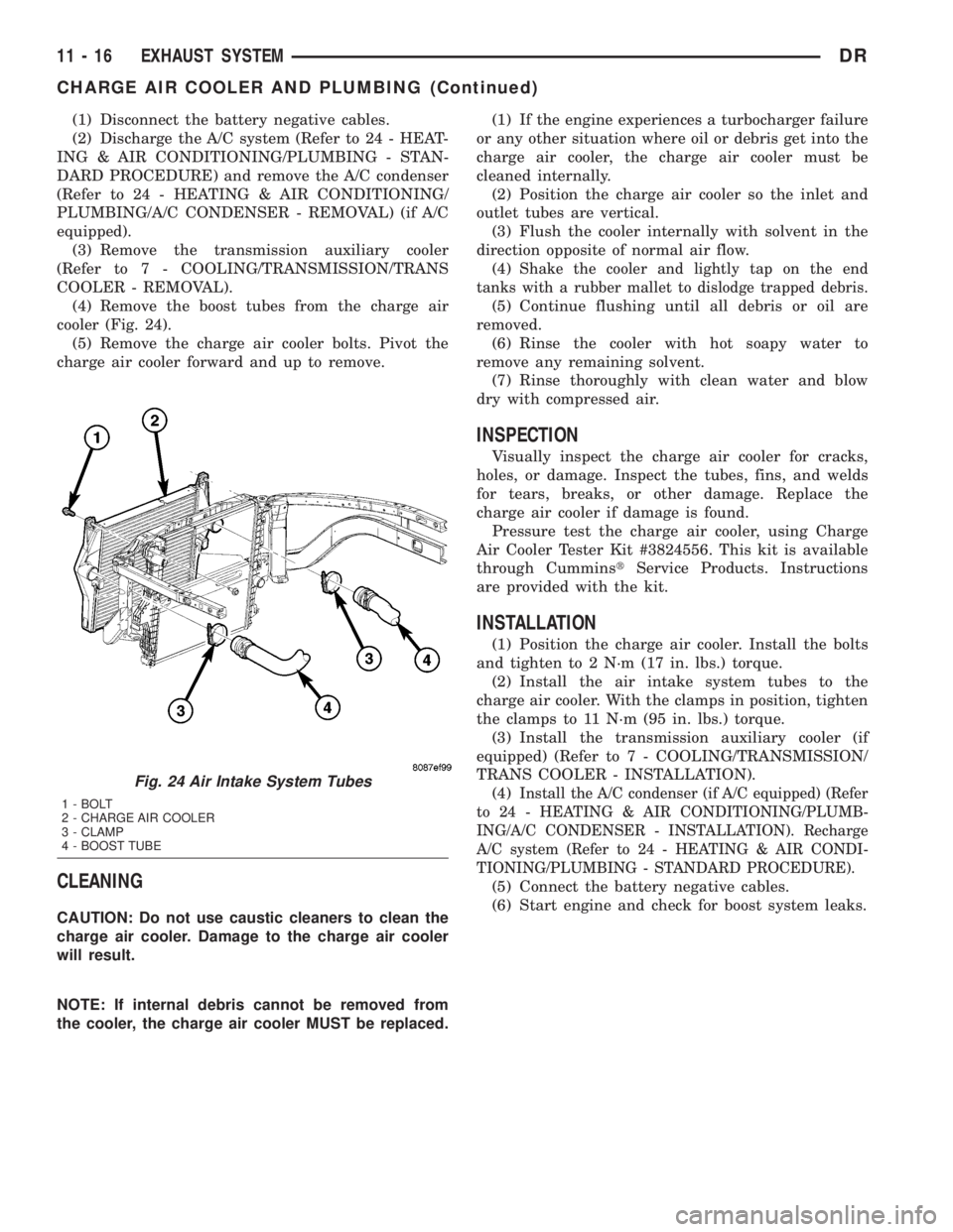
(1) Disconnect the battery negative cables.
(2) Discharge the A/C system (Refer to 24 - HEAT-
ING & AIR CONDITIONING/PLUMBING - STAN-
DARD PROCEDURE) and remove the A/C condenser
(Refer to 24 - HEATING & AIR CONDITIONING/
PLUMBING/A/C CONDENSER - REMOVAL) (if A/C
equipped).
(3) Remove the transmission auxiliary cooler
(Refer to 7 - COOLING/TRANSMISSION/TRANS
COOLER - REMOVAL).
(4) Remove the boost tubes from the charge air
cooler (Fig. 24).
(5) Remove the charge air cooler bolts. Pivot the
charge air cooler forward and up to remove.
CLEANING
CAUTION: Do not use caustic cleaners to clean the
charge air cooler. Damage to the charge air cooler
will result.
NOTE: If internal debris cannot be removed from
the cooler, the charge air cooler MUST be replaced.(1) If the engine experiences a turbocharger failure
or any other situation where oil or debris get into the
charge air cooler, the charge air cooler must be
cleaned internally.
(2) Position the charge air cooler so the inlet and
outlet tubes are vertical.
(3) Flush the cooler internally with solvent in the
direction opposite of normal air flow.
(4)
Shake the cooler and lightly tap on the end
tanks with a rubber mallet to dislodge trapped debris.
(5) Continue flushing until all debris or oil are
removed.
(6) Rinse the cooler with hot soapy water to
remove any remaining solvent.
(7) Rinse thoroughly with clean water and blow
dry with compressed air.
INSPECTION
Visually inspect the charge air cooler for cracks,
holes, or damage. Inspect the tubes, fins, and welds
for tears, breaks, or other damage. Replace the
charge air cooler if damage is found.
Pressure test the charge air cooler, using Charge
Air Cooler Tester Kit #3824556. This kit is available
through CumminstService Products. Instructions
are provided with the kit.
INSTALLATION
(1) Position the charge air cooler. Install the bolts
and tighten to 2 N´m (17 in. lbs.) torque.
(2) Install the air intake system tubes to the
charge air cooler. With the clamps in position, tighten
the clamps to 11 N´m (95 in. lbs.) torque.
(3) Install the transmission auxiliary cooler (if
equipped) (Refer to 7 - COOLING/TRANSMISSION/
TRANS COOLER - INSTALLATION).
(4)
Install the A/C condenser (if A/C equipped) (Refer
to 24 - HEATING & AIR CONDITIONING/PLUMB-
ING/A/C CONDENSER - INSTALLATION). Recharge
A/C system (Refer to 24 - HEATING & AIR CONDI-
TIONING/PLUMBING - STANDARD PROCEDURE).
(5) Connect the battery negative cables.
(6) Start engine and check for boost system leaks.
Fig. 24 Air Intake System Tubes
1 - BOLT
2 - CHARGE AIR COOLER
3 - CLAMP
4 - BOOST TUBE
11 - 16 EXHAUST SYSTEMDR
CHARGE AIR COOLER AND PLUMBING (Continued)