sensor DODGE RAM 2003 Service Repair Manual
[x] Cancel search | Manufacturer: DODGE, Model Year: 2003, Model line: RAM, Model: DODGE RAM 2003Pages: 2895, PDF Size: 83.15 MB
Page 2519 of 2895
SPECIFICATIONS
TRANSFER CASE - NV243
TORQUE SPECIFICATIONS
DESCRIPTION N-m Ft. Lbs. In. Lbs.
Plug, Detent 16-24 12-18 -
Plug, Drain/Fill 40-45 30-40 -
Bolt, Extension Housing 16-24 12-18 -
Bolt, Case Half 20-27 15-24 -
Screw, Oil Pump 12-16 8-12 -
Nuts, Mounting 30-41 20-30 -
Bolts, Shift Motor and
Mode Sensor Assembly16-24 12-18 -
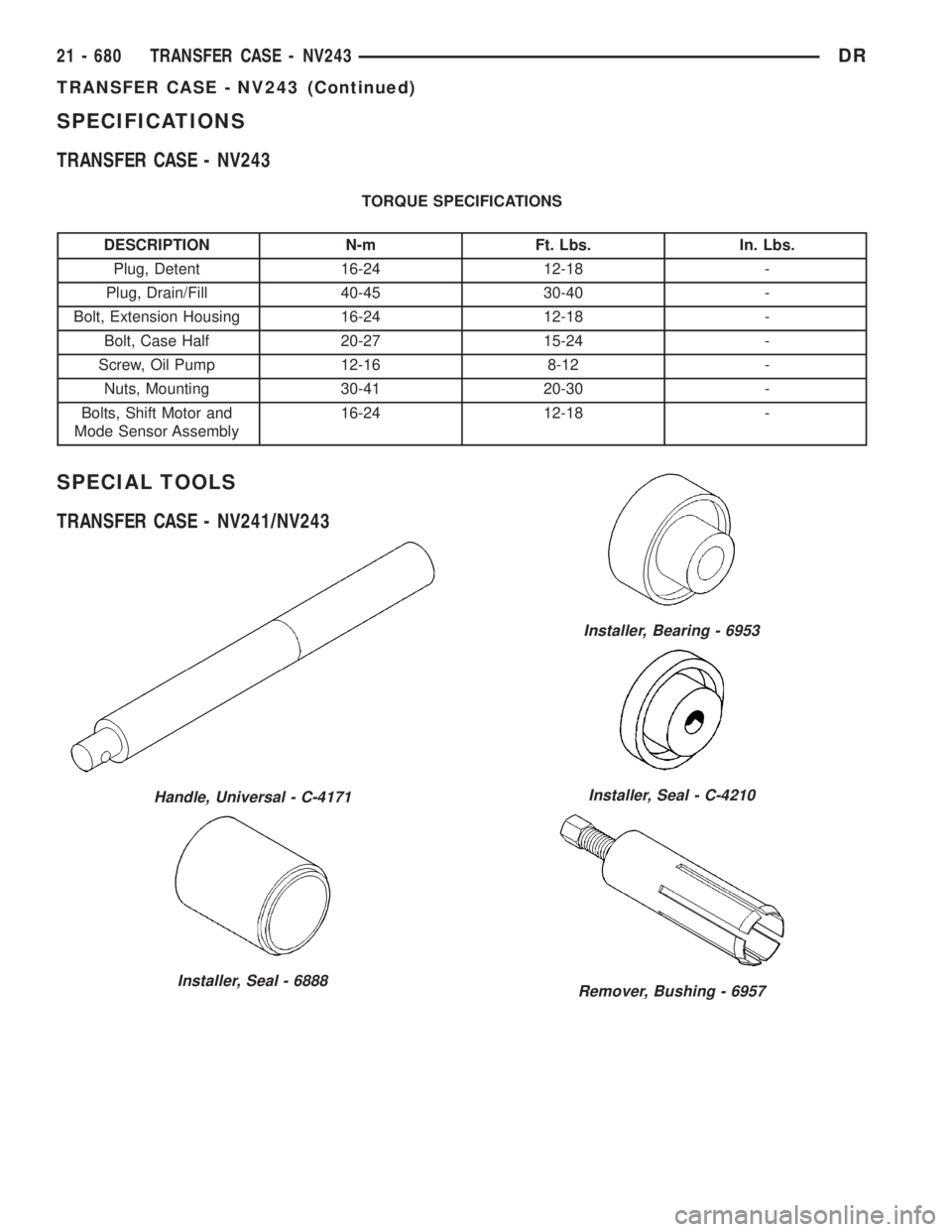
SPECIAL TOOLS
TRANSFER CASE - NV241/NV243
Handle, Universal - C-4171
Installer, Seal - 6888
Installer, Bearing - 6953
Installer, Seal - C-4210
Remover, Bushing - 6957
21 - 680 TRANSFER CASE - NV243DR
TRANSFER CASE - NV243 (Continued)
Page 2523 of 2895
MODE SENSOR
DESCRIPTION
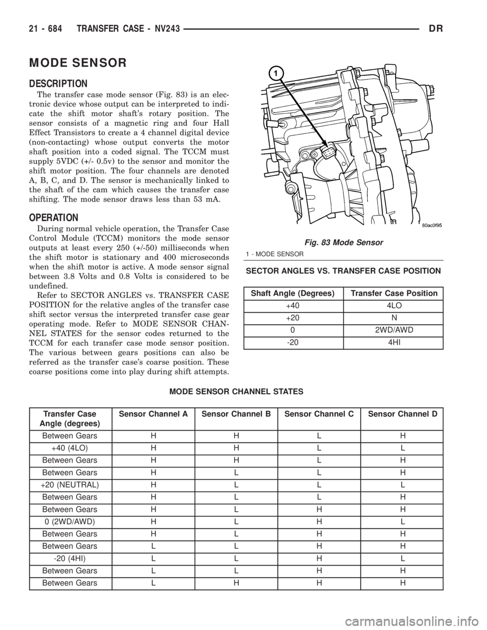
The transfer case mode sensor (Fig. 83) is an elec-
tronic device whose output can be interpreted to indi-
cate the shift motor shaft's rotary position. The
sensor consists of a magnetic ring and four Hall
Effect Transistors to create a 4 channel digital device
(non-contacting) whose output converts the motor
shaft position into a coded signal. The TCCM must
supply 5VDC (+/- 0.5v) to the sensor and monitor the
shift motor position. The four channels are denoted
A, B, C, and D. The sensor is mechanically linked to
the shaft of the cam which causes the transfer case
shifting. The mode sensor draws less than 53 mA.
OPERATION
During normal vehicle operation, the Transfer Case
Control Module (TCCM) monitors the mode sensor
outputs at least every 250 (+/-50) milliseconds when
the shift motor is stationary and 400 microseconds
when the shift motor is active. A mode sensor signal
between 3.8 Volts and 0.8 Volts is considered to be
undefined.
Refer to SECTOR ANGLES vs. TRANSFER CASE
POSITION for the relative angles of the transfer case
shift sector versus the interpreted transfer case gear
operating mode. Refer to MODE SENSOR CHAN-
NEL STATES for the sensor codes returned to the
TCCM for each transfer case mode sensor position.
The various between gears positions can also be
referred as the transfer case's coarse position. These
coarse positions come into play during shift attempts.SECTOR ANGLES VS. TRANSFER CASE POSITION
Shaft Angle (Degrees) Transfer Case Position
+40 4LO
+20 N
0 2WD/AWD
-20 4HI
MODE SENSOR CHANNEL STATES
Transfer Case
Angle (degrees)Sensor Channel A Sensor Channel B Sensor Channel C Sensor Channel D
Between Gears H H L H
+40 (4LO) H H L L
Between Gears H H L H
Between Gears H L L H
+20 (NEUTRAL) H L L L
Between Gears H L L H
Between Gears H L H H
0 (2WD/AWD) H L H L
Between Gears H L H H
Between Gears L L H H
-20 (4HI) L L H L
Between Gears L L H H
Between Gears L H H H
Fig. 83 Mode Sensor
1 - MODE SENSOR
21 - 684 TRANSFER CASE - NV243DR
Page 2524 of 2895
SELECTOR SWITCH
DESCRIPTION
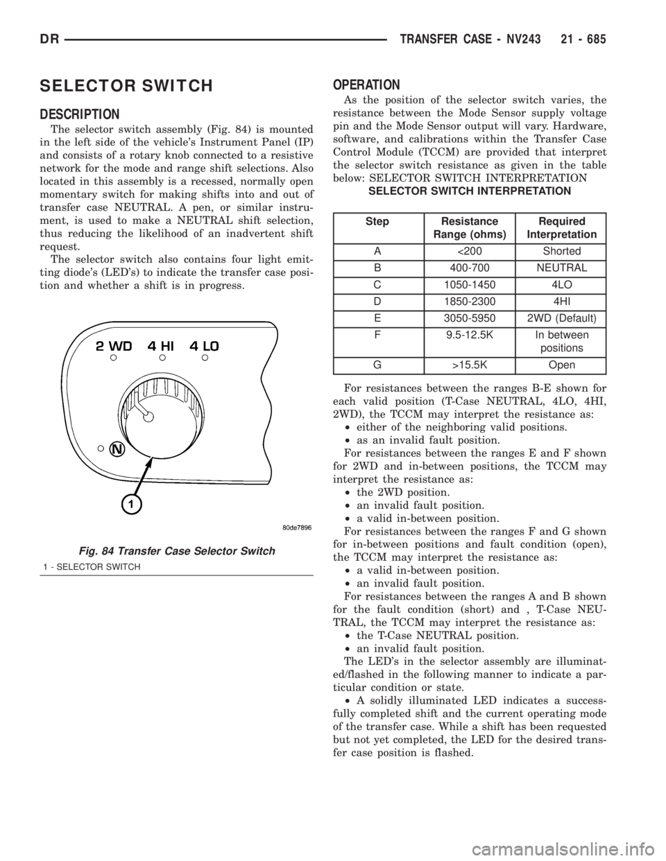
The selector switch assembly (Fig. 84) is mounted
in the left side of the vehicle's Instrument Panel (IP)
and consists of a rotary knob connected to a resistive
network for the mode and range shift selections. Also
located in this assembly is a recessed, normally open
momentary switch for making shifts into and out of
transfer case NEUTRAL. A pen, or similar instru-
ment, is used to make a NEUTRAL shift selection,
thus reducing the likelihood of an inadvertent shift
request.
The selector switch also contains four light emit-
ting diode's (LED's) to indicate the transfer case posi-
tion and whether a shift is in progress.
OPERATION
As the position of the selector switch varies, the
resistance between the Mode Sensor supply voltage
pin and the Mode Sensor output will vary. Hardware,
software, and calibrations within the Transfer Case
Control Module (TCCM) are provided that interpret
the selector switch resistance as given in the table
below: SELECTOR SWITCH INTERPRETATION
SELECTOR SWITCH INTERPRETATION
Step Resistance
Range (ohms)Required
Interpretation
A <200 Shorted
B 400-700 NEUTRAL
C 1050-1450 4LO
D 1850-2300 4HI
E 3050-5950 2WD (Default)
F 9.5-12.5K In between
positions
G >15.5K Open
For resistances between the ranges B-E shown for
each valid position (T-Case NEUTRAL, 4LO, 4HI,
2WD), the TCCM may interpret the resistance as:
²either of the neighboring valid positions.
²as an invalid fault position.
For resistances between the ranges E and F shown
for 2WD and in-between positions, the TCCM may
interpret the resistance as:
²the 2WD position.
²an invalid fault position.
²a valid in-between position.
For resistances between the ranges F and G shown
for in-between positions and fault condition (open),
the TCCM may interpret the resistance as:
²a valid in-between position.
²an invalid fault position.
For resistances between the ranges A and B shown
for the fault condition (short) and , T-Case NEU-
TRAL, the TCCM may interpret the resistance as:
²the T-Case NEUTRAL position.
²an invalid fault position.
The LED's in the selector assembly are illuminat-
ed/flashed in the following manner to indicate a par-
ticular condition or state.
²A solidly illuminated LED indicates a success-
fully completed shift and the current operating mode
of the transfer case. While a shift has been requested
but not yet completed, the LED for the desired trans-
fer case position is flashed.
Fig. 84 Transfer Case Selector Switch
1 - SELECTOR SWITCH
DRTRANSFER CASE - NV243 21 - 685
Page 2525 of 2895
²A flashing operating mode LED for the desired
gear indicates that a shift to that position has been
requested, but all of the driver controllable conditions
have not been met. This is in an attempt to notify
the driver that the transmission needs to be put into
NEUTRAL, the vehicle speed is too great, or some
other condition outlined (other than a diagnostic fail-
ure that would prevent this shift) elsewhere (Refer to
8 - ELECTRICAL/ELECTRONIC CONTROL MOD-
ULES/TRANSFER CASE CONTROL MODULE -
OPERATION) is not met. Note that this flashing will
continue indefinitely until the conditions are eventu-
ally met, or the selector switch position is changed,
or if diagnostic routines no longer allow the
requested shift.
²If the driver attempts to make a shift into trans-
fer case NEUTRAL, and any of the driver controlla-
ble conditions are not met, the request will be
ignored until all of the conditions are met or until
the NEUTRAL select button is released. Additionally
the neutral lamp will flash, or begin to flash while
the button is depressed and operator controllable
conditions are not being met. All of the LED's except
the Neutral will flash if any of the operator control-
lable conditions for shifting are not met while the
Neutral button is depressed. This9toggle9type of fea-
ture is necessary because the TCCM would interpret
another request immediately after the shift into
transfer case NEUTRAL has completed.
²No LED's illuminated indicate a fault in the
transfer case control system.
SHIFT MOTOR
DESCRIPTION
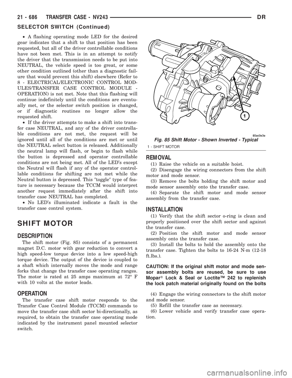
The shift motor (Fig. 85) consists of a permanent
magnet D.C. motor with gear reduction to convert a
high speed-low torque device into a low speed-high
torque device. The output of the device is coupled to
a shaft which internally moves the mode and range
forks that change the transfer case operating ranges.
The motor is rated at 25 amps maximum at 72É F
with 10 volts at the motor leads.
OPERATION
The transfer case shift motor responds to the
Transfer Case Control Module (TCCM) commands to
move the transfer case shift sector bi-directionally, as
required, to obtain the transfer case operating mode
indicated by the instrument panel mounted selector
switch.
REMOVAL
(1) Raise the vehicle on a suitable hoist.
(2) Disengage the wiring connectors from the shift
motor and mode sensor.
(3) Remove the bolts holding the shift motor and
mode sensor assembly onto the transfer case.
(4) Separate the shift motor and mode sensor
assembly from the transfer case.
INSTALLATION
(1) Verify that the shift sector o-ring is clean and
properly positioned over the shift sector and against
the transfer case.
(2) Position the shift motor and mode sensor
assembly onto the transfer case.
(3) Install the bolts to hold the assembly onto the
transfer case. Tighten the bolts to 16-24 N´m (12-18
ft.lbs.).
CAUTION: If the original shift motor and mode sen-
sor assembly bolts are reused, be sure to use
MoparTLock & Seal or LoctiteŸ 242 to replenish
the lock patch material originally found on the bolts
(4) Engage the wiring connectors to the shift motor
and mode sensor.
(5) Refill the transfer case as necessary.
(6) Lower vehicle and verify transfer case opera-
tion.
Fig. 85 Shift Motor - Shown Inverted - Typical
1 - SHIFT MOTOR
21 - 686 TRANSFER CASE - NV243DR
SELECTOR SWITCH (Continued)
Page 2526 of 2895
TRANSFER CASE - NV273
TABLE OF CONTENTS
page page
TRANSFER CASE - NV273
DESCRIPTION........................687
OPERATION..........................688
DIAGNOSIS AND TESTING - TRANSFER
CASE - NV273.......................688
REMOVAL............................689
DISASSEMBLY........................689
CLEANING...........................698
INSPECTION.........................699
ASSEMBLY...........................701
INSTALLATION........................713
SPECIFICATIONS
TRANSFER CASE - NV273.............713
SPECIAL TOOLS
TRANSFER CASE NV271/NV273.........714
EXTENSION HOUSING SEAL AND DUST BOOT
REMOVAL............................716
INSTALLATION........................716FLUID
STANDARD PROCEDURE - FLUID DRAIN AND
REFILL............................716
FRONT OUTPUT SHAFT SEAL
REMOVAL............................717
INSTALLATION........................717
MODE SENSOR
DESCRIPTION........................718
OPERATION..........................718
SELECTOR SWITCH
DESCRIPTION........................719
OPERATION..........................719
SHIFT MOTOR
DESCRIPTION........................720
OPERATION..........................720
REMOVAL............................720
INSTALLATION........................720
TRANSFER CASE - NV273
DESCRIPTION
The NV273 is an electronically controlled part-time
transfer case with a low range gear reduction system.
The NV273 has three operating ranges plus a NEU-
TRAL position. The low range system provides a gear
reduction ratio for increased low speed torque capa-
bility.
The geartrain is mounted in two aluminum case
halves attached with bolts. The mainshaft front and
rear bearings are mounted in aluminum case halves.
OPERATING RANGES
Transfer case operating ranges are:
²2WD (2-wheel drive)
²4HI (4-wheel drive)
²4LO (4-wheel drive low range)
²NEUTRAL
The 2WD range is for use on any road surface at
any time.The 4HI and 4LO ranges are for off road use only.
They are not for use on hard surface roads. The only
exception being when the road surface is wet or slip-
pery or covered by ice and snow.
The low range reduction gear system is operative
in 4LO range only. This range is for extra pulling
power in off road situations. Low range reduction
ratio is 2.72:1.
SHIFT MECHANISM
Operating ranges are selected with a dash
mounted shift selector switch. The shift selector
switch provides a input to the Transfer Case Control
Module (TCCM) to indicate the driver's desire to
change operating ranges. The TCCM uses this input,
along with input from the transfer case mounted
mode sensor and information from the vehicle's bus,
to determine if a shift is permitted. If the TCCM
decides the shift is permitted, the TCCM controls the
shift motor, mounted to the exterior of the transfer
case, to perform the shift.
DRTRANSFER CASE - NV273 21 - 687
Page 2528 of 2895
Condition Possible Cause Correction
Transfer case noisy while in, or
jumps out of, 4LO mode.1) Transfer case not completely
engaged in 4LO position.1) While rolling 2-3 MPH and the
transmission in NEUTRAL, or clutch
depressed on vehicles equipped
with a manual transmission, shift
transfer case to the 2WD or 4HI
position, and then back into the 4LO
position.
2) Range fork damaged, inserts
worn, or fork is binding on the shift
rail.2) Repair or replace components as
necessary.
3) Low range gear worn or
damaged.3) Repair or replace components as
necessary.
Lubricant leaking from transfer case
seals or vent.1) Transfer case overfilled. 1) Drain lubricant to the correct
level.
2) Transfer case vent closed or
restricted.2) Clean or replace vent as
necessary.
3) Transfer case seals damaged or
installed incorrectly.3) Replace suspect seal.
Abnormal tire wear. 1) Extended operation in 4HI mode
on dry surfaces,1) Operate vehicle in 2WD mode on
dry surfaces.
REMOVAL
(1) Shift transfer case into 2WD.
(2) Raise vehicle.
(3) Drain transfer case lubricant.
(4) Mark front and rear propeller shafts for align-
ment reference.
(5) Support transmission with jack stand.
(6) Remove the transfer case skid plate, if
equipped.
(7) Disconnect front and rear propeller shafts at
transfer case.
(8) Disconnect transfer case shift motor and mode
sensor wire connectors.
(9) Disconnect transfer case vent hose.
(10) Support transfer case with transmission jack.
(11) Secure transfer case to jack with chains.
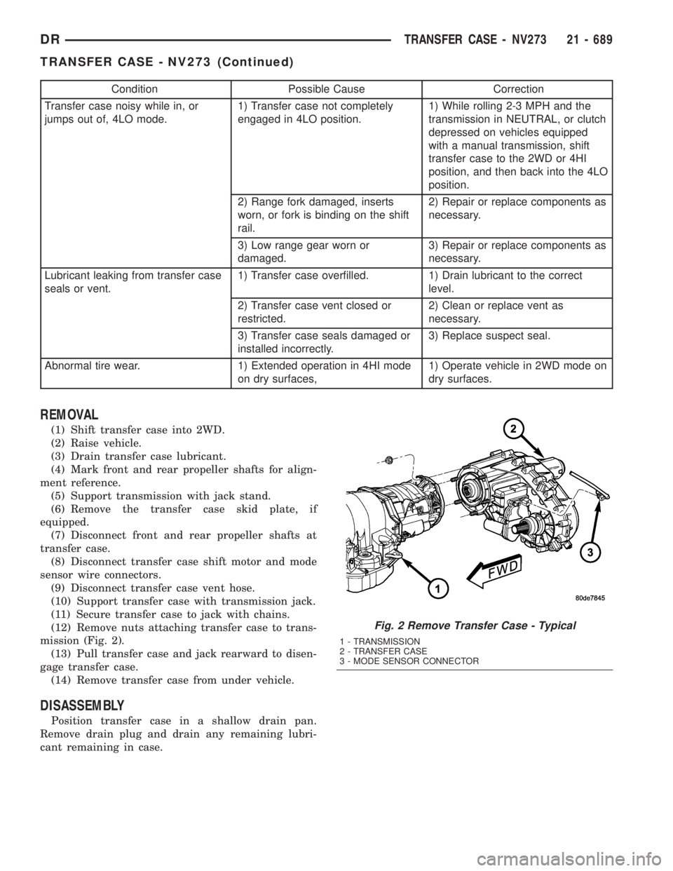
(12) Remove nuts attaching transfer case to trans-
mission (Fig. 2).
(13) Pull transfer case and jack rearward to disen-
gage transfer case.
(14) Remove transfer case from under vehicle.
DISASSEMBLY
Position transfer case in a shallow drain pan.
Remove drain plug and drain any remaining lubri-
cant remaining in case.
Fig. 2 Remove Transfer Case - Typical
1 - TRANSMISSION
2 - TRANSFER CASE
3 - MODE SENSOR CONNECTOR
DRTRANSFER CASE - NV273 21 - 689
TRANSFER CASE - NV273 (Continued)
Page 2547 of 2895
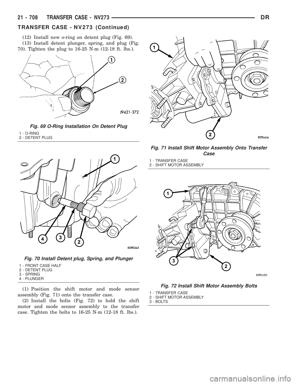
(12) Install new o-ring on detent plug (Fig. 69).
(13) Install detent plunger, spring, and plug (Fig.
70). Tighten the plug to 16-25 N´m (12-18 ft. lbs.).
(1) Position the shift motor and mode sensor
assembly (Fig. 71) onto the transfer case.
(2) Install the bolts (Fig. 72) to hold the shift
motor and mode sensor assembly to the transfer
case. Tighten the bolts to 16-25 N´m (12-18 ft. lbs.).
Fig. 69 O-Ring Installation On Detent Plug
1 - O-RING
2 - DETENT PLUG
Fig. 70 Install Detent plug, Spring, and Plunger
1 - FRONT CASE HALF
2 - DETENT PLUG
3 - SPRING
4 - PLUNGER
Fig. 71 Install Shift Motor Assembly Onto Transfer
Case
1 - TRANSFER CASE
2 - SHIFT MOTOR ASSEMBLY
Fig. 72 Install Shift Motor Assembly Bolts
1 - TRANSFER CASE
2 - SHIFT MOTOR ASSEMBLY
3 - BOLTS
21 - 708 TRANSFER CASE - NV273DR
TRANSFER CASE - NV273 (Continued)
Page 2552 of 2895
(7) Install the front companion flange onto the
front output shaft.
(8) Install two bolts 180É apart into the front out-
put shaft companion flange.
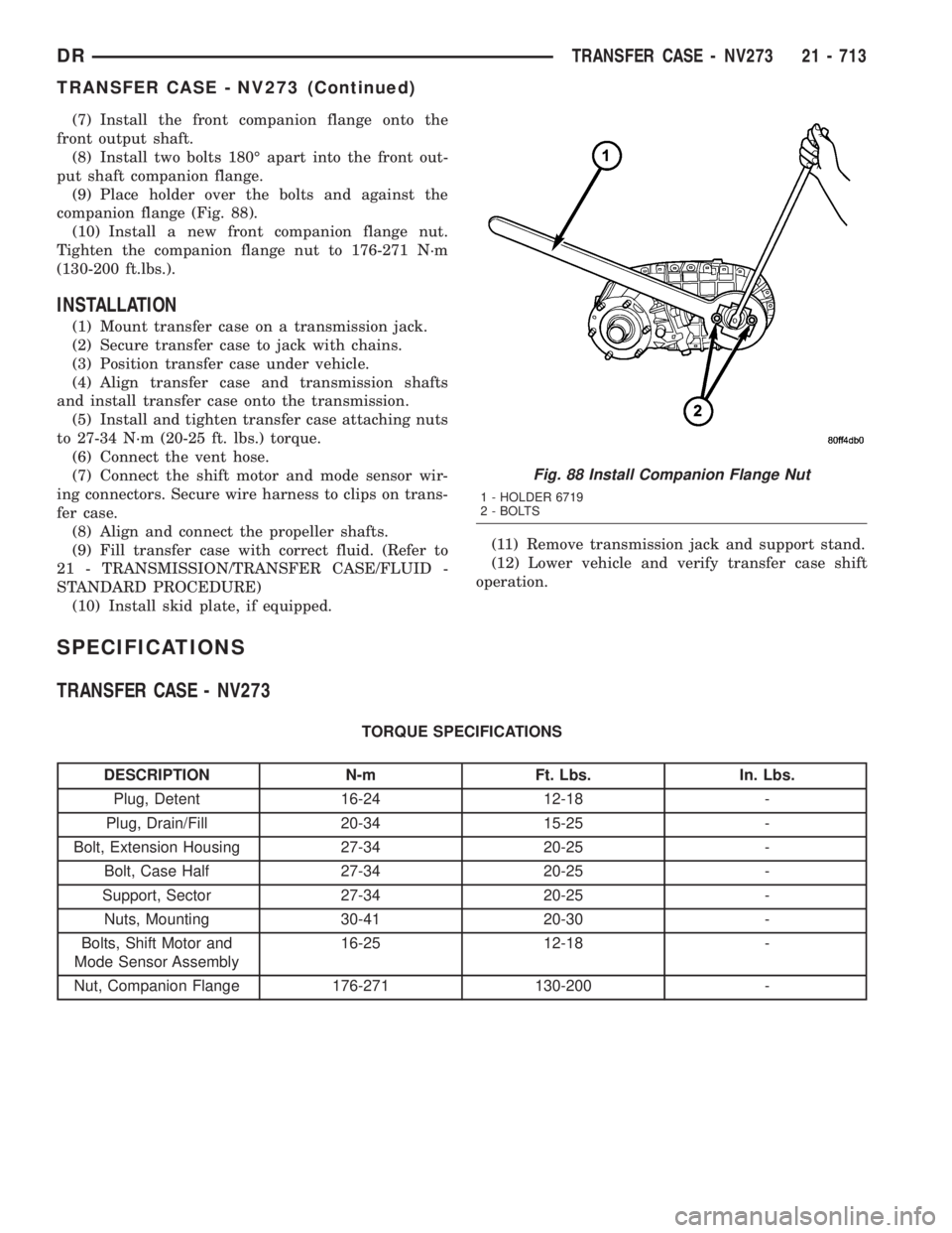
(9) Place holder over the bolts and against the
companion flange (Fig. 88).
(10) Install a new front companion flange nut.
Tighten the companion flange nut to 176-271 N´m
(130-200 ft.lbs.).
INSTALLATION
(1) Mount transfer case on a transmission jack.
(2) Secure transfer case to jack with chains.
(3) Position transfer case under vehicle.
(4) Align transfer case and transmission shafts
and install transfer case onto the transmission.
(5) Install and tighten transfer case attaching nuts
to 27-34 N´m (20-25 ft. lbs.) torque.
(6) Connect the vent hose.
(7) Connect the shift motor and mode sensor wir-
ing connectors. Secure wire harness to clips on trans-
fer case.
(8) Align and connect the propeller shafts.
(9) Fill transfer case with correct fluid. (Refer to
21 - TRANSMISSION/TRANSFER CASE/FLUID -
STANDARD PROCEDURE)
(10) Install skid plate, if equipped.(11) Remove transmission jack and support stand.
(12) Lower vehicle and verify transfer case shift
operation.
SPECIFICATIONS
TRANSFER CASE - NV273
TORQUE SPECIFICATIONS
DESCRIPTION N-m Ft. Lbs. In. Lbs.
Plug, Detent 16-24 12-18 -
Plug, Drain/Fill 20-34 15-25 -
Bolt, Extension Housing 27-34 20-25 -
Bolt, Case Half 27-34 20-25 -
Support, Sector 27-34 20-25 -
Nuts, Mounting 30-41 20-30 -
Bolts, Shift Motor and
Mode Sensor Assembly16-25 12-18 -
Nut, Companion Flange 176-271 130-200 -
Fig. 88 Install Companion Flange Nut
1 - HOLDER 6719
2 - BOLTS
DRTRANSFER CASE - NV273 21 - 713
TRANSFER CASE - NV273 (Continued)
Page 2557 of 2895
MODE SENSOR
DESCRIPTION
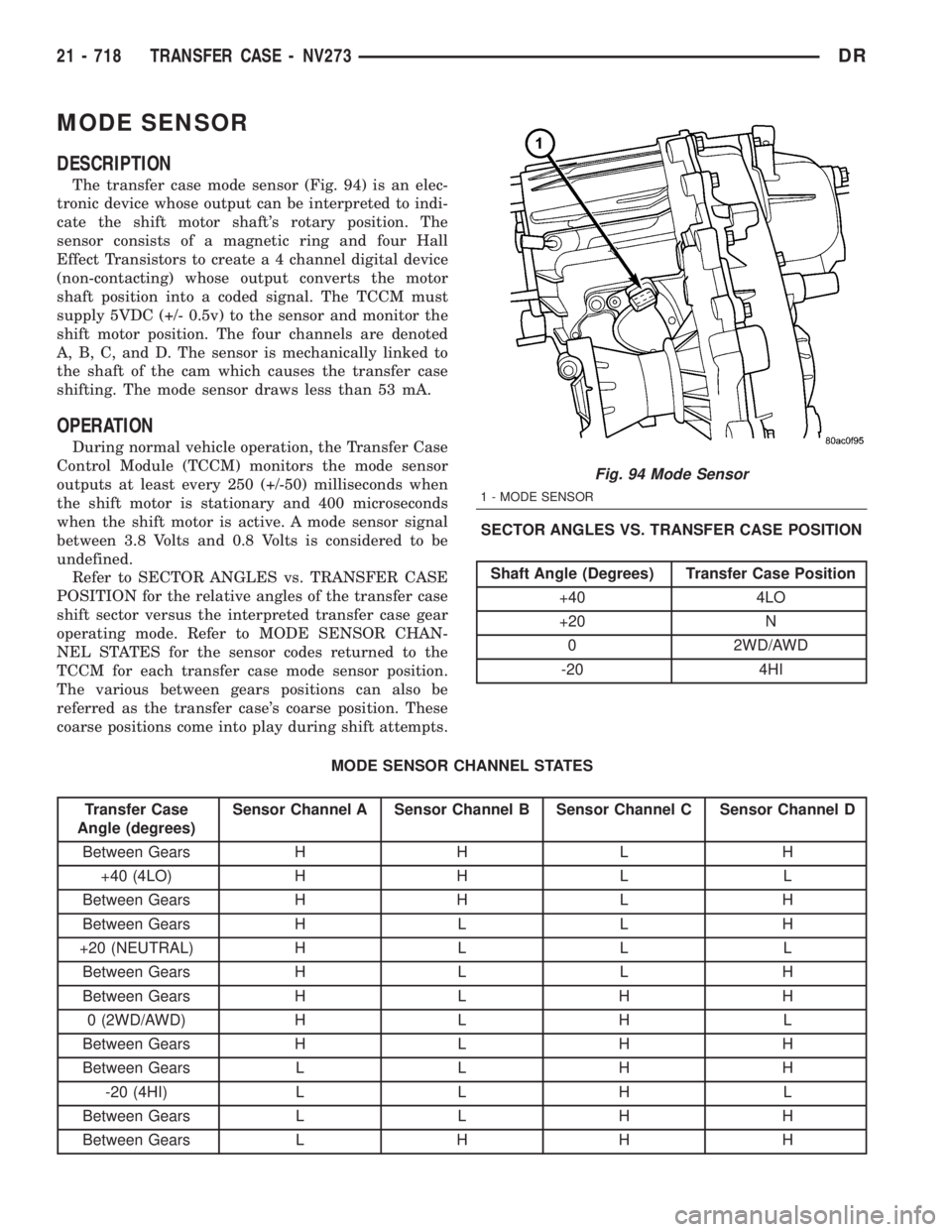
The transfer case mode sensor (Fig. 94) is an elec-
tronic device whose output can be interpreted to indi-
cate the shift motor shaft's rotary position. The
sensor consists of a magnetic ring and four Hall
Effect Transistors to create a 4 channel digital device
(non-contacting) whose output converts the motor
shaft position into a coded signal. The TCCM must
supply 5VDC (+/- 0.5v) to the sensor and monitor the
shift motor position. The four channels are denoted
A, B, C, and D. The sensor is mechanically linked to
the shaft of the cam which causes the transfer case
shifting. The mode sensor draws less than 53 mA.
OPERATION
During normal vehicle operation, the Transfer Case
Control Module (TCCM) monitors the mode sensor
outputs at least every 250 (+/-50) milliseconds when
the shift motor is stationary and 400 microseconds
when the shift motor is active. A mode sensor signal
between 3.8 Volts and 0.8 Volts is considered to be
undefined.
Refer to SECTOR ANGLES vs. TRANSFER CASE
POSITION for the relative angles of the transfer case
shift sector versus the interpreted transfer case gear
operating mode. Refer to MODE SENSOR CHAN-
NEL STATES for the sensor codes returned to the
TCCM for each transfer case mode sensor position.
The various between gears positions can also be
referred as the transfer case's coarse position. These
coarse positions come into play during shift attempts.SECTOR ANGLES VS. TRANSFER CASE POSITION
Shaft Angle (Degrees) Transfer Case Position
+40 4LO
+20 N
0 2WD/AWD
-20 4HI
MODE SENSOR CHANNEL STATES
Transfer Case
Angle (degrees)Sensor Channel A Sensor Channel B Sensor Channel C Sensor Channel D
Between Gears H H L H
+40 (4LO) H H L L
Between Gears H H L H
Between Gears H L L H
+20 (NEUTRAL) H L L L
Between Gears H L L H
Between Gears H L H H
0 (2WD/AWD) H L H L
Between Gears H L H H
Between Gears L L H H
-20 (4HI) L L H L
Between Gears L L H H
Between Gears L H H H
Fig. 94 Mode Sensor
1 - MODE SENSOR
21 - 718 TRANSFER CASE - NV273DR
Page 2558 of 2895
SELECTOR SWITCH
DESCRIPTION
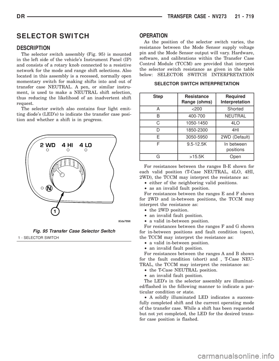
The selector switch assembly (Fig. 95) is mounted
in the left side of the vehicle's Instrument Panel (IP)
and consists of a rotary knob connected to a resistive
network for the mode and range shift selections. Also
located in this assembly is a recessed, normally open
momentary switch for making shifts into and out of
transfer case NEUTRAL. A pen, or similar instru-
ment, is used to make a NEUTRAL shift selection,
thus reducing the likelihood of an inadvertent shift
request.
The selector switch also contains four light emit-
ting diode's (LED's) to indicate the transfer case posi-
tion and whether a shift is in progress.
OPERATION
As the position of the selector switch varies, the
resistance between the Mode Sensor supply voltage
pin and the Mode Sensor output will vary. Hardware,
software, and calibrations within the Transfer Case
Control Module (TCCM) are provided that interpret
the selector switch resistance as given in the table
below: SELECTOR SWITCH INTERPRETATION
SELECTOR SWITCH INTERPRETATION
Step Resistance
Range (ohms)Required
Interpretation
A <200 Shorted
B 400-700 NEUTRAL
C 1050-1450 4LO
D 1850-2300 4HI
E 3050-5950 2WD (Default)
F 9.5-12.5K In between
positions
G >15.5K Open
For resistances between the ranges B-E shown for
each valid position (T-Case NEUTRAL, 4LO, 4HI,
2WD), the TCCM may interpret the resistance as:
²either of the neighboring valid positions.
²as an invalid fault position.
For resistances between the ranges E and F shown
for 2WD and in-between positions, the TCCM may
interpret the resistance as:
²the 2WD position.
²an invalid fault position.
²a valid in-between position.
For resistances between the ranges F and G shown
for in-between positions and fault condition (open),
the TCCM may interpret the resistance as:
²a valid in-between position.
²an invalid fault position.
For resistances between the ranges A and B shown
for the fault condition (short) and , T-Case NEU-
TRAL, the TCCM may interpret the resistance as:
²the T-Case NEUTRAL position.
²an invalid fault position.
The LED's in the selector assembly are illuminat-
ed/flashed in the following manner to indicate a par-
ticular condition or state.
²A solidly illuminated LED indicates a success-
fully completed shift and the current operating mode
of the transfer case. While a shift has been requested
but not yet completed, the LED for the desired trans-
fer case position is flashed.
Fig. 95 Transfer Case Selector Switch
1 - SELECTOR SWITCH
DRTRANSFER CASE - NV273 21 - 719