sensor DODGE RAM 2003 Service Repair Manual
[x] Cancel search | Manufacturer: DODGE, Model Year: 2003, Model line: RAM, Model: DODGE RAM 2003Pages: 2895, PDF Size: 83.15 MB
Page 2559 of 2895
²A flashing operating mode LED for the desired
gear indicates that a shift to that position has been
requested, but all of the driver controllable conditions
have not been met. This is in an attempt to notify
the driver that the transmission needs to be put into
NEUTRAL, the vehicle speed is too great, or some
other condition outlined (other than a diagnostic fail-
ure that would prevent this shift) elsewhere (Refer to
8 - ELECTRICAL/ELECTRONIC CONTROL MOD-
ULES/TRANSFER CASE CONTROL MODULE -
OPERATION) is not met. Note that this flashing will
continue indefinitely until the conditions are eventu-
ally met, or the selector switch position is changed,
or if diagnostic routines no longer allow the
requested shift.
²If the driver attempts to make a shift into trans-
fer case NEUTRAL, and any of the driver controlla-
ble conditions are not met, the request will be
ignored until all of the conditions are met or until
the NEUTRAL select button is released. Additionally
the neutral lamp will flash, or begin to flash while
the button is depressed and operator controllable
conditions are not being met. All of the LED's except
the Neutral will flash if any of the operator control-
lable conditions for shifting are not met while the
Neutral button is depressed. This9toggle9type of fea-
ture is necessary because the TCCM would interpret
another request immediately after the shift into
transfer case NEUTRAL has completed.
²No LED's illuminated indicate a fault in the
transfer case control system.
SHIFT MOTOR
DESCRIPTION
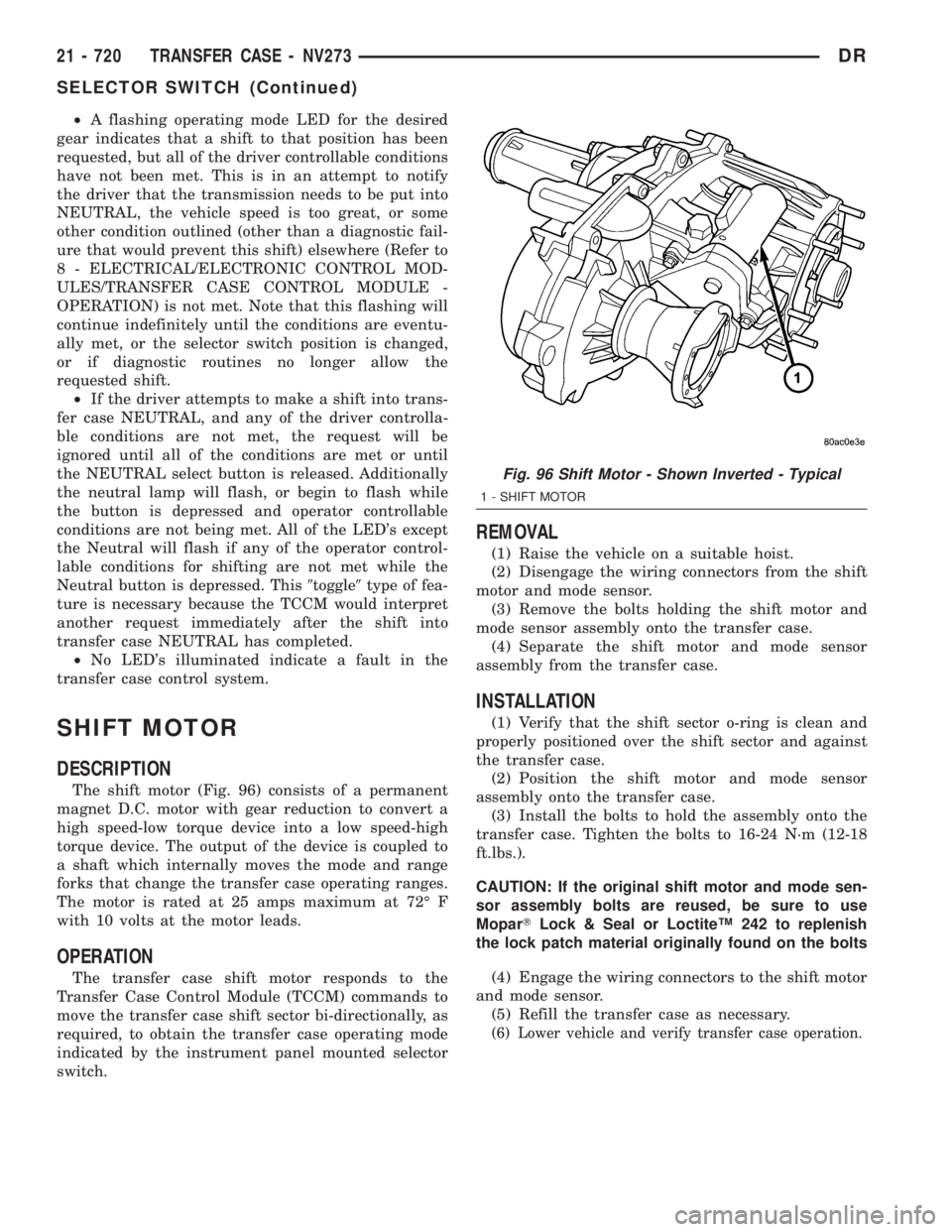
The shift motor (Fig. 96) consists of a permanent
magnet D.C. motor with gear reduction to convert a
high speed-low torque device into a low speed-high
torque device. The output of the device is coupled to
a shaft which internally moves the mode and range
forks that change the transfer case operating ranges.
The motor is rated at 25 amps maximum at 72É F
with 10 volts at the motor leads.
OPERATION
The transfer case shift motor responds to the
Transfer Case Control Module (TCCM) commands to
move the transfer case shift sector bi-directionally, as
required, to obtain the transfer case operating mode
indicated by the instrument panel mounted selector
switch.
REMOVAL
(1) Raise the vehicle on a suitable hoist.
(2) Disengage the wiring connectors from the shift
motor and mode sensor.
(3) Remove the bolts holding the shift motor and
mode sensor assembly onto the transfer case.
(4) Separate the shift motor and mode sensor
assembly from the transfer case.
INSTALLATION
(1) Verify that the shift sector o-ring is clean and
properly positioned over the shift sector and against
the transfer case.
(2) Position the shift motor and mode sensor
assembly onto the transfer case.
(3) Install the bolts to hold the assembly onto the
transfer case. Tighten the bolts to 16-24 N´m (12-18
ft.lbs.).
CAUTION: If the original shift motor and mode sen-
sor assembly bolts are reused, be sure to use
MoparTLock & Seal or LoctiteŸ 242 to replenish
the lock patch material originally found on the bolts
(4) Engage the wiring connectors to the shift motor
and mode sensor.
(5) Refill the transfer case as necessary.
(6) Lower vehicle and verify transfer case operation.
Fig. 96 Shift Motor - Shown Inverted - Typical
1 - SHIFT MOTOR
21 - 720 TRANSFER CASE - NV273DR
SELECTOR SWITCH (Continued)
Page 2622 of 2895
HOOD
REMOVAL
(1) Open the hood.
(2) Using a grease pencil or equivalent, mark the
position of the hinges on the hood.
(3) Remove the hood hinge nuts and remove the
hood.
(4) Remove the grille. (Refer to 23 - BODY/EXTE-
RIOR/GRILLE - REMOVAL)
(5) Remove the hood lamp and ambient tempera-
ture sensor.
INSTALLATION
(1) Install the hood lamp and ambient temperature
sensor.
(2) Install the grille. (Refer to 23 - BODY/EXTERI-
OR/GRILLE - INSTALLATION)
(3) Install the hood and install the nuts.
(4) Line up the marks made previously and
tighten the nuts to 23 N´m (17 ft. lbs.).
(5) Check the hood fit and adjust if required.
(Refer to 23 - BODY/BODY STRUCTURE/GAP AND
FLUSH - SPECIFICATIONS)
LATCH
REMOVAL
(1) Open the hood.
(2) Using a grease pencil or equivalent, mark the
position of the latch on the radiator crossmember.
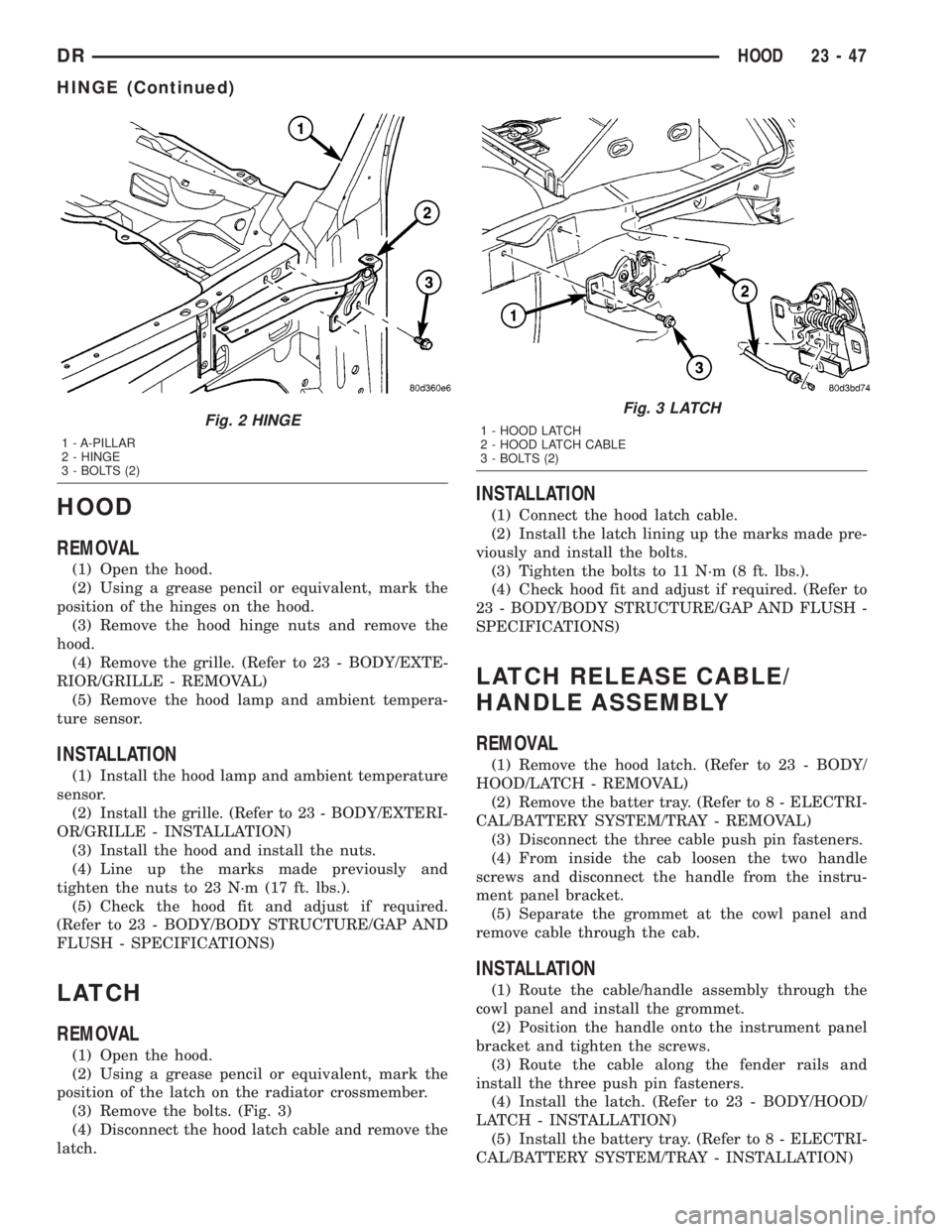
(3) Remove the bolts. (Fig. 3)
(4) Disconnect the hood latch cable and remove the
latch.
INSTALLATION
(1) Connect the hood latch cable.
(2) Install the latch lining up the marks made pre-
viously and install the bolts.
(3) Tighten the bolts to 11 N´m (8 ft. lbs.).
(4) Check hood fit and adjust if required. (Refer to
23 - BODY/BODY STRUCTURE/GAP AND FLUSH -
SPECIFICATIONS)
LATCH RELEASE CABLE/
HANDLE ASSEMBLY
REMOVAL
(1) Remove the hood latch. (Refer to 23 - BODY/
HOOD/LATCH - REMOVAL)
(2) Remove the batter tray. (Refer to 8 - ELECTRI-
CAL/BATTERY SYSTEM/TRAY - REMOVAL)
(3) Disconnect the three cable push pin fasteners.
(4) From inside the cab loosen the two handle
screws and disconnect the handle from the instru-
ment panel bracket.
(5) Separate the grommet at the cowl panel and
remove cable through the cab.
INSTALLATION
(1) Route the cable/handle assembly through the
cowl panel and install the grommet.
(2) Position the handle onto the instrument panel
bracket and tighten the screws.
(3) Route the cable along the fender rails and
install the three push pin fasteners.
(4) Install the latch. (Refer to 23 - BODY/HOOD/
LATCH - INSTALLATION)
(5) Install the battery tray. (Refer to 8 - ELECTRI-
CAL/BATTERY SYSTEM/TRAY - INSTALLATION)
Fig. 2 HINGE
1 - A-PILLAR
2 - HINGE
3 - BOLTS (2)
Fig. 3 LATCH
1 - HOOD LATCH
2 - HOOD LATCH CABLE
3 - BOLTS (2)
DRHOOD 23 - 47
HINGE (Continued)
Page 2779 of 2895
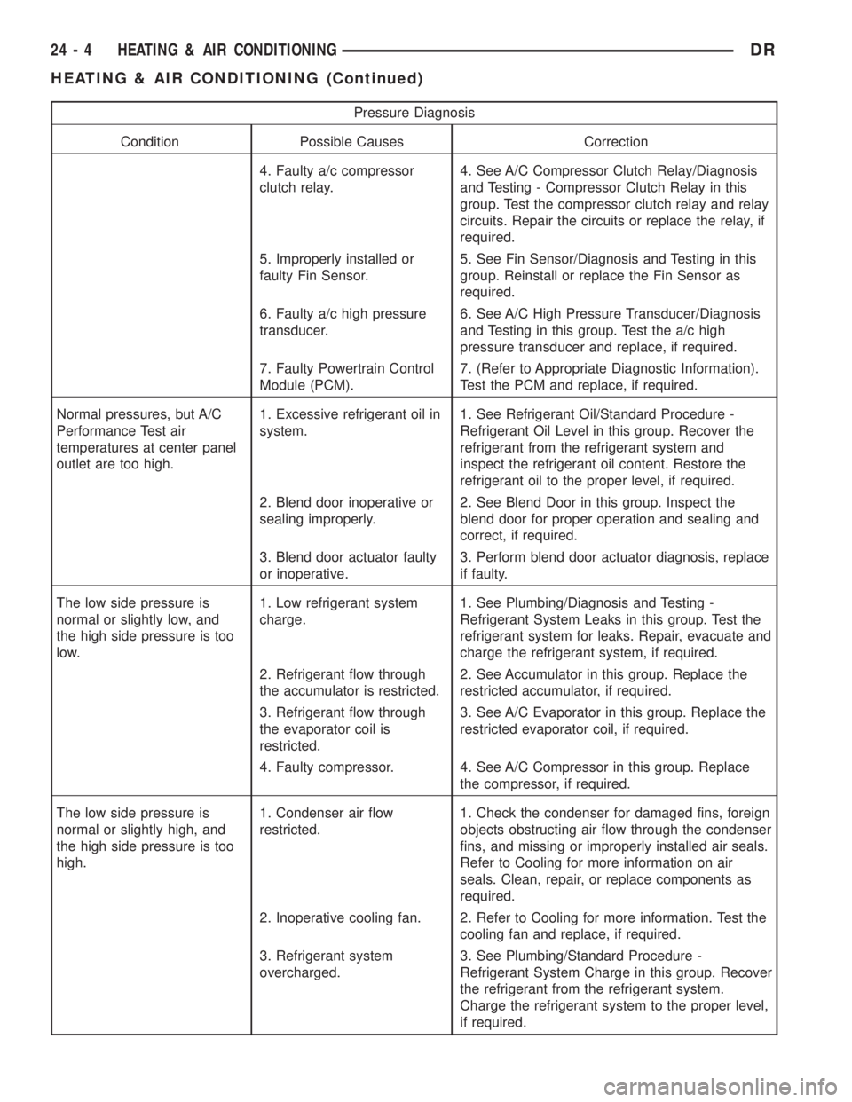
Pressure Diagnosis
Condition Possible Causes Correction
4. Faulty a/c compressor
clutch relay.4. See A/C Compressor Clutch Relay/Diagnosis
and Testing - Compressor Clutch Relay in this
group. Test the compressor clutch relay and relay
circuits. Repair the circuits or replace the relay, if
required.
5. Improperly installed or
faulty Fin Sensor.5. See Fin Sensor/Diagnosis and Testing in this
group. Reinstall or replace the Fin Sensor as
required.
6. Faulty a/c high pressure
transducer.6. See A/C High Pressure Transducer/Diagnosis
and Testing in this group. Test the a/c high
pressure transducer and replace, if required.
7. Faulty Powertrain Control
Module (PCM).7. (Refer to Appropriate Diagnostic Information).
Test the PCM and replace, if required.
Normal pressures, but A/C
Performance Test air
temperatures at center panel
outlet are too high.1. Excessive refrigerant oil in
system.1. See Refrigerant Oil/Standard Procedure -
Refrigerant Oil Level in this group. Recover the
refrigerant from the refrigerant system and
inspect the refrigerant oil content. Restore the
refrigerant oil to the proper level, if required.
2. Blend door inoperative or
sealing improperly.2. See Blend Door in this group. Inspect the
blend door for proper operation and sealing and
correct, if required.
3. Blend door actuator faulty
or inoperative.3. Perform blend door actuator diagnosis, replace
if faulty.
The low side pressure is
normal or slightly low, and
the high side pressure is too
low.1. Low refrigerant system
charge.1. See Plumbing/Diagnosis and Testing -
Refrigerant System Leaks in this group. Test the
refrigerant system for leaks. Repair, evacuate and
charge the refrigerant system, if required.
2. Refrigerant flow through
the accumulator is restricted.2. See Accumulator in this group. Replace the
restricted accumulator, if required.
3. Refrigerant flow through
the evaporator coil is
restricted.3. See A/C Evaporator in this group. Replace the
restricted evaporator coil, if required.
4. Faulty compressor. 4. See A/C Compressor in this group. Replace
the compressor, if required.
The low side pressure is
normal or slightly high, and
the high side pressure is too
high.1. Condenser air flow
restricted.1. Check the condenser for damaged fins, foreign
objects obstructing air flow through the condenser
fins, and missing or improperly installed air seals.
Refer to Cooling for more information on air
seals. Clean, repair, or replace components as
required.
2. Inoperative cooling fan. 2. Refer to Cooling for more information. Test the
cooling fan and replace, if required.
3. Refrigerant system
overcharged.3. See Plumbing/Standard Procedure -
Refrigerant System Charge in this group. Recover
the refrigerant from the refrigerant system.
Charge the refrigerant system to the proper level,
if required.
24 - 4 HEATING & AIR CONDITIONINGDR
HEATING & AIR CONDITIONING (Continued)
Page 2782 of 2895
STANDARD PROCEDURE - DIODE
REPLACEMENT
(1) Disconnect the battery negative cable and iso-
late it. If vehicle has a dual batterys remove both
negative cables.
(2) Locate the diode in the harness, and remove
the protective covering.
(3) Remove the diode from the harness, pay atten-
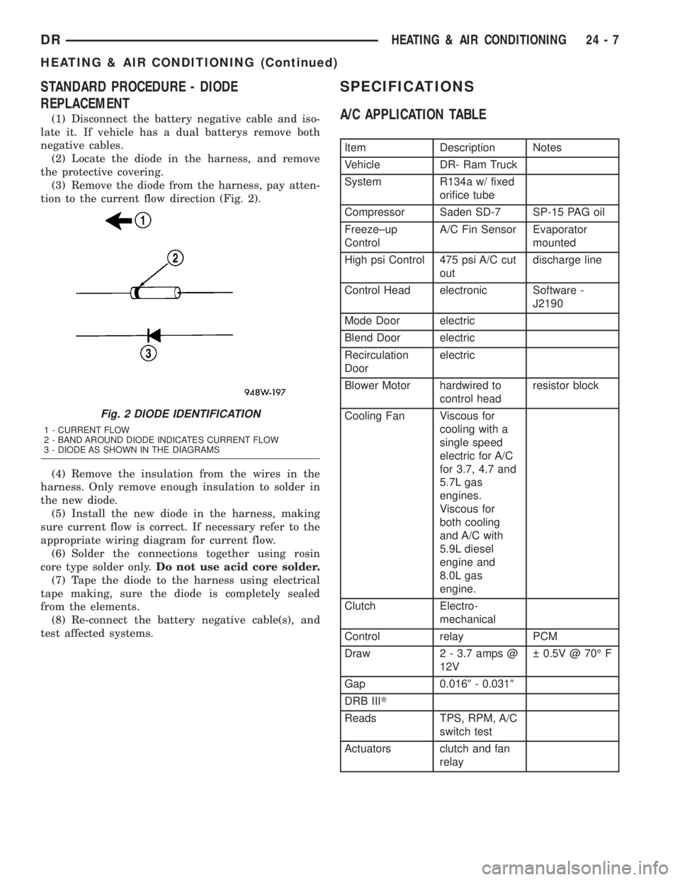
tion to the current flow direction (Fig. 2).
(4) Remove the insulation from the wires in the
harness. Only remove enough insulation to solder in
the new diode.
(5) Install the new diode in the harness, making
sure current flow is correct. If necessary refer to the
appropriate wiring diagram for current flow.
(6) Solder the connections together using rosin
core type solder only.Do not use acid core solder.
(7) Tape the diode to the harness using electrical
tape making, sure the diode is completely sealed
from the elements.
(8) Re-connect the battery negative cable(s), and
test affected systems.
SPECIFICATIONS
A/C APPLICATION TABLE
Item Description Notes
Vehicle DR- Ram Truck
System R134a w/ fixed
orifice tube
Compressor Saden SD-7 SP-15 PAG oil
Freeze±up
ControlA/C Fin Sensor Evaporator
mounted
High psi Control 475 psi A/C cut
outdischarge line
Control Head electronic Software -
J2190
Mode Door electric
Blend Door electric
Recirculation
Doorelectric
Blower Motor hardwired to
control headresistor block
Cooling Fan Viscous for
cooling with a
single speed
electric for A/C
for 3.7, 4.7 and
5.7L gas
engines.
Viscous for
both cooling
and A/C with
5.9L diesel
engine and
8.0L gas
engine.
Clutch Electro-
mechanical
Control relay PCM
Draw 2 - 3.7 amps @
12V 0.5V @ 70É F
Gap 0.0169- 0.0319
DRB IIIT
Reads TPS, RPM, A/C
switch test
Actuators clutch and fan
relay
Fig. 2 DIODE IDENTIFICATION
1 - CURRENT FLOW
2 - BAND AROUND DIODE INDICATES CURRENT FLOW
3 - DIODE AS SHOWN IN THE DIAGRAMS
DRHEATING & AIR CONDITIONING 24 - 7
HEATING & AIR CONDITIONING (Continued)
Page 2790 of 2895
INSTALLATION
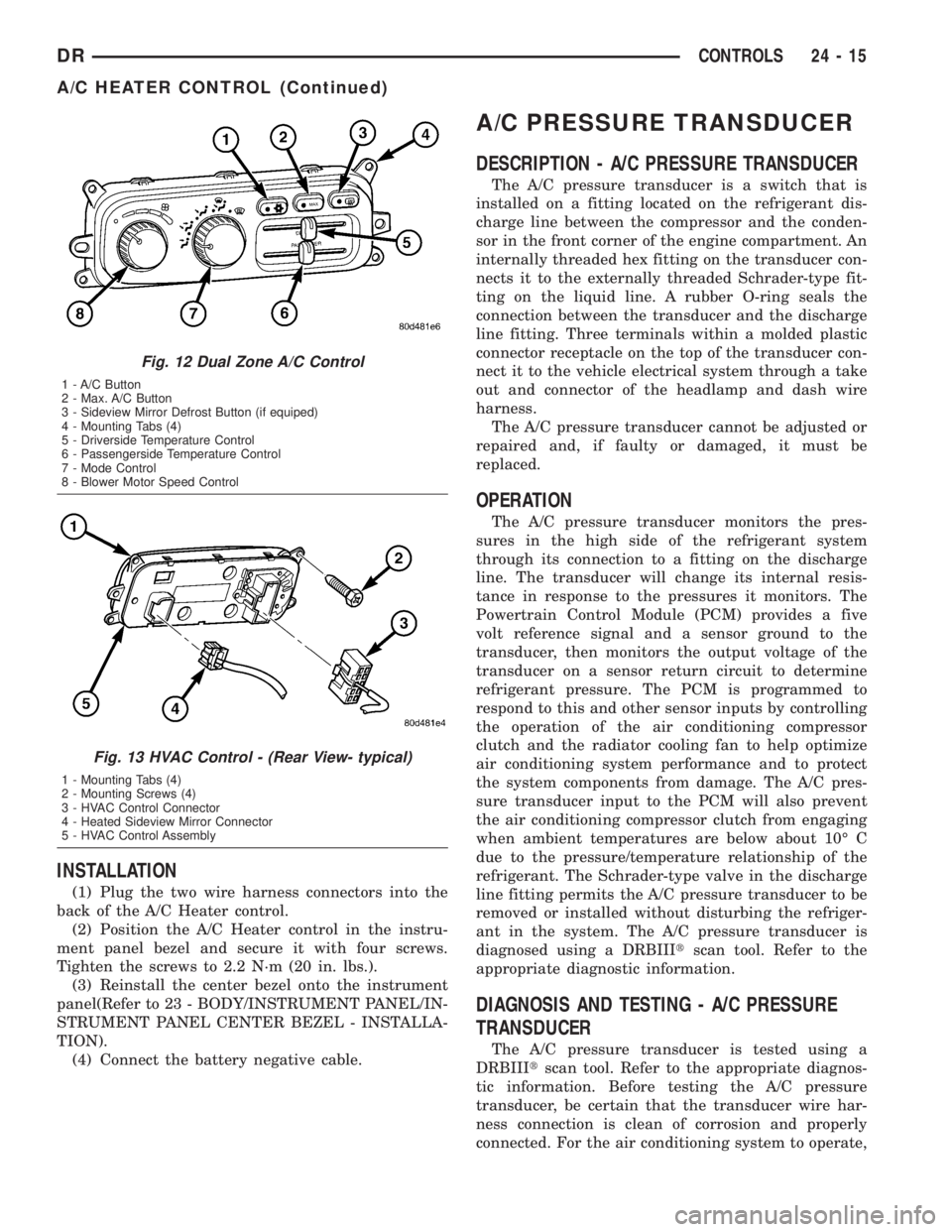
(1) Plug the two wire harness connectors into the
back of the A/C Heater control.
(2) Position the A/C Heater control in the instru-
ment panel bezel and secure it with four screws.
Tighten the screws to 2.2 N´m (20 in. lbs.).
(3) Reinstall the center bezel onto the instrument
panel(Refer to 23 - BODY/INSTRUMENT PANEL/IN-
STRUMENT PANEL CENTER BEZEL - INSTALLA-
TION).
(4) Connect the battery negative cable.
A/C PRESSURE TRANSDUCER
DESCRIPTION - A/C PRESSURE TRANSDUCER
The A/C pressure transducer is a switch that is
installed on a fitting located on the refrigerant dis-
charge line between the compressor and the conden-
sor in the front corner of the engine compartment. An
internally threaded hex fitting on the transducer con-
nects it to the externally threaded Schrader-type fit-
ting on the liquid line. A rubber O-ring seals the
connection between the transducer and the discharge
line fitting. Three terminals within a molded plastic
connector receptacle on the top of the transducer con-
nect it to the vehicle electrical system through a take
out and connector of the headlamp and dash wire
harness.
The A/C pressure transducer cannot be adjusted or
repaired and, if faulty or damaged, it must be
replaced.
OPERATION
The A/C pressure transducer monitors the pres-
sures in the high side of the refrigerant system
through its connection to a fitting on the discharge
line. The transducer will change its internal resis-
tance in response to the pressures it monitors. The
Powertrain Control Module (PCM) provides a five
volt reference signal and a sensor ground to the
transducer, then monitors the output voltage of the
transducer on a sensor return circuit to determine
refrigerant pressure. The PCM is programmed to
respond to this and other sensor inputs by controlling
the operation of the air conditioning compressor
clutch and the radiator cooling fan to help optimize
air conditioning system performance and to protect
the system components from damage. The A/C pres-
sure transducer input to the PCM will also prevent
the air conditioning compressor clutch from engaging
when ambient temperatures are below about 10É C
due to the pressure/temperature relationship of the
refrigerant. The Schrader-type valve in the discharge
line fitting permits the A/C pressure transducer to be
removed or installed without disturbing the refriger-
ant in the system. The A/C pressure transducer is
diagnosed using a DRBIIItscan tool. Refer to the
appropriate diagnostic information.
DIAGNOSIS AND TESTING - A/C PRESSURE
TRANSDUCER
The A/C pressure transducer is tested using a
DRBIIItscan tool. Refer to the appropriate diagnos-
tic information. Before testing the A/C pressure
transducer, be certain that the transducer wire har-
ness connection is clean of corrosion and properly
connected. For the air conditioning system to operate,
Fig. 12 Dual Zone A/C Control
1 - A/C Button
2 - Max. A/C Button
3 - Sideview Mirror Defrost Button (if equiped)
4 - Mounting Tabs (4)
5 - Driverside Temperature Control
6 - Passengerside Temperature Control
7 - Mode Control
8 - Blower Motor Speed Control
Fig. 13 HVAC Control - (Rear View- typical)
1 - Mounting Tabs (4)
2 - Mounting Screws (4)
3 - HVAC Control Connector
4 - Heated Sideview Mirror Connector
5 - HVAC Control Assembly
DRCONTROLS 24 - 15
A/C HEATER CONTROL (Continued)
Page 2791 of 2895
an A/C pressure transducer voltage reading between
0.451 and 4.519 volts is required. Voltages outside
this range indicate a low or high refrigerant system
pressure condition to the Powertrain Control Module
(PCM). The PCM is programmed to respond to a low
or high refrigerant system pressure by suppressing
operation of the compressor. Refer to the A/C Pres-
sure Transducer Voltage table for the possible condi-
tion indicated by the transducer voltage readings.
A/C PRESSURE TRANSDUCER VOLTAGE
VOLTAGE POSSIBLE INDICATION
0.0 1. NO SENSOR SUPPLY
VOLTAGE FROM PCM.
2. SHORTED SENSOR CIRCUIT.
3. FAULTY TRANSDUCER.
0.150 TO 0.450 1. AMBIENT TEMPERATURE
BELOW 10É C (50É F).
2. LOW REFRIGERANT
SYSTEM PRESSURE.
0.451 TO 4.519 1. NORMAL REFRIGERANT
SYSTEM PRESSURE.
4.520 TO 4.850 1. HIGH REFRIGERANT
SYSTEM PRESSURE.
5.0 1. OPEN SENSOR CIRCUIT.
2. FAULTY TRANSDUCER.
REMOVAL
(1) Disconnect and isolate the battery negative
cable.
(2) Disconnect the wire harness connector for the
A/C pressure transducer from the transducer connec-
tor receptacle.
(3) Using an open end wrench, unscrew the A/C
pressure transducer from the fitting on the discharge
line between the compressor and the condenser.
(4) Remove the seal from the A/C pressure trans-
ducer fitting and discard.
INSTALLATION
(1) Lubricate a new rubber O-ring seal with clean
refrigerant oil and install it on the A/C pressure
transducer fitting.
(2) Using an open end wrench, install and tighten
the A/C pressure transducer onto the fitting on the
discharge line between the compressor and the con-
denser.
(3) Reconnect the wire harness connector for the
A/C pressure transducer to the transducer connector
receptacle.
(4) Reconnect the battery negative cable.
BLEND DOOR ACTUATOR
DESCRIPTION
The blend door actuators are reversible, 12-volt
Direct Current (DC), servo motors. Models with the
single zone heater and air conditioner system have a
single blend air door, which is controlled by a single
blend door actuator. Models with the optional dual
zone front heater and air conditioner system have
dual blend air doors, which are controlled by two
blend door actuators. The single zone blend door
actuator is located on the driver side end of the heat-
er-A/C housing unit, close to the dash panel. In the
dual zone system, the same blend door actuator used
for the single zone system becomes the driver side
blend door actuator, and is mechanically connected to
only the driver side blend air door. In the dual zone
system, a second separate blend door actuator is also
located on the top of the heater-A/C housing unit and
is mechanically connected to only the passenger side
blend air door.
The blend door actuators are interchangeable with
each other, as well as with the actuators for the
mode door and the recirculation air door. Each actua-
tor is contained within an identical black molded
plastic housing with an integral wire connector
receptacle. Two integral mounting tabs allow the
actuator to be secured with two screws to the heater-
A/C unit housing. Each actuator also has an identical
output shaft with splines that connects it to the link-
age that drives the proper blend air door. The blend
door actuators do not require mechanical indexing to
the blend door linkage, as they are electronically cal-
ibrated by the heater-A/C control module. The blend
door actuators cannot be adjusted or repaired and, if
damaged or faulty, they must be replaced.
OPERATION
Each blend door actuator is connected to the heat-
er-A/C control module through the vehicle electrical
system by a dedicated two-wire take out and connec-
tor of the HVAC wire harness. The blend door actua-
tor can move the blend air door in two directions.
When the heater-A/C control module pulls the volt-
age on one side of the motor connection high and the
other connection low, the blend air door will move in
one direction. When the module reverses the polarity
of the voltage to the motor, the blend air door moves
in the opposite direction. When the module makes
the voltage to both connections high or both connec-
tions low, the blend air door stops and will not move.
These same motor connections also provide a feed-
back signal to the heater-A/C control module. This
feedback signal allows the module to monitor the
operation and relative positions of the blend door
actuator and the blend air door. The heater-A/C con-
24 - 16 CONTROLSDR
A/C PRESSURE TRANSDUCER (Continued)
Page 2800 of 2895
(1) Recover refrigerant(Refer to 24 - HEATING &
AIR CONDITIONING/PLUMBING - STANDARD
PROCEDURE).
(2) Remove and disassemble the HVAC housing.
(Refer to 24 - HEATING & AIR CONDITIONING/
DISTRIBUTION/HVAC HOUSING - REMOVAL)
(Refer to 24 - HEATING & AIR CONDITIONING/
DISTRIBUTION/HVAC HOUSING - DISASSEMBLY)
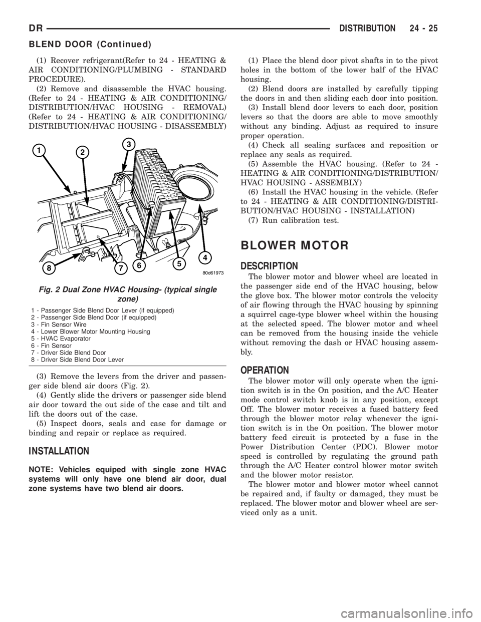
(3) Remove the levers from the driver and passen-
ger side blend air doors (Fig. 2).
(4) Gently slide the drivers or passenger side blend
air door toward the out side of the case and tilt and
lift the doors out of the case.
(5) Inspect doors, seals and case for damage or
binding and repair or replace as required.
INSTALLATION
NOTE: Vehicles equiped with single zone HVAC
systems will only have one blend air door, dual
zone systems have two blend air doors.(1) Place the blend door pivot shafts in to the pivot
holes in the bottom of the lower half of the HVAC
housing.
(2) Blend doors are installed by carefully tipping
the doors in and then sliding each door into position.
(3) Install blend door levers to each door, position
levers so that the doors are able to move smoothly
without any binding. Adjust as required to insure
proper operation.
(4) Check all sealing surfaces and reposition or
replace any seals as required.
(5) Assemble the HVAC housing. (Refer to 24 -
HEATING & AIR CONDITIONING/DISTRIBUTION/
HVAC HOUSING - ASSEMBLY)
(6) Install the HVAC housing in the vehicle. (Refer
to 24 - HEATING & AIR CONDITIONING/DISTRI-
BUTION/HVAC HOUSING - INSTALLATION)
(7) Run calibration test.
BLOWER MOTOR
DESCRIPTION
The blower motor and blower wheel are located in
the passenger side end of the HVAC housing, below
the glove box. The blower motor controls the velocity
of air flowing through the HVAC housing by spinning
a squirrel cage-type blower wheel within the housing
at the selected speed. The blower motor and wheel
can be removed from the housing inside the vehicle
without removing the dash or HVAC housing assem-
bly.
OPERATION
The blower motor will only operate when the igni-
tion switch is in the On position, and the A/C Heater
mode control switch knob is in any position, except
Off. The blower motor receives a fused battery feed
through the blower motor relay whenever the igni-
tion switch is in the On position. The blower motor
battery feed circuit is protected by a fuse in the
Power Distribution Center (PDC). Blower motor
speed is controlled by regulating the ground path
through the A/C Heater control blower motor switch
and the blower motor resistor.
The blower motor and blower motor wheel cannot
be repaired and, if faulty or damaged, they must be
replaced. The blower motor and blower wheel are ser-
viced only as a unit.
Fig. 2 Dual Zone HVAC Housing- (typical single
zone)
1 - Passenger Side Blend Door Lever (if equipped)
2 - Passenger Side Blend Door (if equipped)
3 - Fin Sensor Wire
4 - Lower Blower Motor Mounting Housing
5 - HVAC Evaporator
6 - Fin Sensor
7 - Driver Side Blend Door
8 - Driver Side Blend Door Lever
DRDISTRIBUTION 24 - 25
BLEND DOOR (Continued)
Page 2823 of 2895
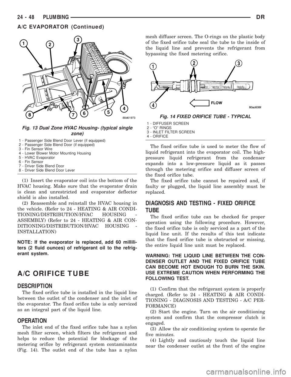
(1) Insert the evaporator coil into the bottom of the
HVAC housing. Make sure that the evaporator drain
is clean and unrestricted and evaporator deflector
shield is also installed.
(2) Reassemble and reinstall the HVAC housing in
the vehicle. (Refer to 24 - HEATING & AIR CONDI-
TIONING/DISTRIBUTION/HVAC HOUSING -
ASSEMBLY) (Refer to 24 - HEATING & AIR CON-
DITIONING/DISTRIBUTION/HVAC HOUSING -
INSTALLATION)
NOTE: If the evaporator is replaced, add 60 millili-
ters (2 fluid ounces) of refrigerant oil to the refrig-
erant system.
A/C ORIFICE TUBE
DESCRIPTION
The fixed orifice tube is installed in the liquid line
between the outlet of the condenser and the inlet of
the evaporator. The fixed orifice tube is only serviced
as an integral part of the liquid line.
OPERATION
The inlet end of the fixed orifice tube has a nylon
mesh filter screen, which filters the refrigerant and
helps to reduce the potential for blockage of the
metering orifice by refrigerant system contaminants
(Fig. 14). The outlet end of the tube has a nylonmesh diffuser screen. The O-rings on the plastic body
of the fixed orifice tube seal the tube to the inside of
the liquid line and prevents the refrigerant from
bypassing the fixed metering orifice.
The fixed orifice tube is used to meter the flow of
liquid refrigerant into the evaporator coil. The high-
pressure liquid refrigerant from the condenser
expands into a low-pressure liquid as it passes
through the metering orifice and diffuser screen of
the fixed orifice tube.
The fixed orifice tube cannot be repaired and, if
faulty or plugged, the liquid line assembly must be
replaced.
DIAGNOSIS AND TESTING - FIXED ORIFICE
TUBE
The fixed orifice tube can be checked for proper
operation using the following procedure. However,
the fixed orifice tube is only serviced as a part of the
liquid line unit. If the results of this test indicate
that the fixed orifice tube is obstructed or missing,
the entire liquid line unit must be replaced.
WARNING: THE LIQUID LINE BETWEEN THE CON-
DENSER OUTLET AND THE FIXED ORIFICE TUBE
CAN BECOME HOT ENOUGH TO BURN THE SKIN.
USE EXTREME CAUTION WHEN PERFORMING THE
FOLLOWING TEST.
(1) Confirm that the refrigerant system is properly
charged. (Refer to 24 - HEATING & AIR CONDI-
TIONING - DIAGNOSIS AND TESTING - A/C PER-
FORMANCE)
(2) Start the engine. Turn on the air conditioning
system and confirm that the compressor clutch is
engaged.
(3) Allow the air conditioning system to operate for
five minutes.
(4) Lightly and cautiously touch the liquid line
near the condenser outlet at the front of the engine
Fig. 13 Dual Zone HVAC Housing- (typical single
zone)
1 - Passenger Side Blend Door Lever (if equipped)
2 - Passenger Side Blend Door (if equipped)
3 - Fin Sensor Wire
4 - Lower Blower Motor Mounting Housing
5 - HVAC Evaporator
6 - Fin Sensor
7 - Driver Side Blend Door
8 - Driver Side Blend Door Lever
Fig. 14 FIXED ORIFICE TUBE - TYPICAL
1 - DIFFUSER SCREEN
2 - ªOº RINGS
3 - INLET FILTER SCREEN
4 - ORIFICE
24 - 48 PLUMBINGDR
A/C EVAPORATOR (Continued)
Page 2830 of 2895
EMISSIONS CONTROL
TABLE OF CONTENTS
page page
EMISSIONS CONTROL
DESCRIPTION
DESCRIPTION - STATE DISPLAY TEST
MODE...............................1
DESCRIPTION - CIRCUIT ACTUATION TEST
MODE...............................1
DESCRIPTION - DIAGNOSTIC TROUBLE
CODES..............................1
DESCRIPTION - TASK MANAGER..........1DESCRIPTION - MONITORED SYSTEMS....1
DESCRIPTION - TRIP DEFINITION.........4
DESCRIPTION - COMPONENT MONITORS . . 4
OPERATION
OPERATION..........................4
OPERATION - TASK MANAGER...........5
OPERATION - NON-MONITORED CIRCUITS . . 8
EVAPORATIVE EMISSIONS................10
EMISSIONS CONTROL
DESCRIPTION
DESCRIPTION - STATE DISPLAY TEST MODE
The switch inputs to the Powertrain Control Mod-
ule (PCM) have two recognized states; HIGH and
LOW. For this reason, the PCM cannot recognize the
difference between a selected switch position versus
an open circuit, a short circuit, or a defective switch.
If the State Display screen shows the change from
HIGH to LOW or LOW to HIGH, assume the entire
switch circuit to the PCM functions properly. Connect
the DRB scan tool to the data link connector and
access the state display screen. Then access either
State Display Inputs and Outputs or State Display
Sensors.
DESCRIPTION - CIRCUIT ACTUATION TEST
MODE
The Circuit Actuation Test Mode checks for proper
operation of output circuits or devices the Powertrain
Control Module (PCM) may not internally recognize.
The PCM attempts to activate these outputs and
allow an observer to verify proper operation. Most of
the tests provide an audible or visual indication of
device operation (click of relay contacts, fuel spray,
etc.). Except for intermittent conditions, if a device
functions properly during testing, assume the device,
its associated wiring, and driver circuit work cor-
rectly. Connect the DRB scan tool to the data link
connector and access the Actuators screen.
DESCRIPTION - DIAGNOSTIC TROUBLE CODES
A Diagnostic Trouble Code (DTC) indicates the
PCM has recognized an abnormal condition in the
system.Remember that DTC's are the results of a sys-
tem or circuit failure, but do not directly iden-
tify the failed component or components.
BULB CHECK
Each time the ignition key is turned to the ON
position, the malfunction indicator (check engine)
lamp on the instrument panel should illuminate for
approximately 2 seconds then go out. This is done for
a bulb check.
OBTAINING DTC'S USING DRB SCAN TOOL
(1) Obtain the applicable Powertrain Diagnostic
Manual.
(2) Obtain the DRB Scan Tool.
(3) Connect the DRB Scan Tool to the data link
(diagnostic) connector. This connector is located in
the passenger compartment; at the lower edge of
instrument panel; near the steering column.
(4) Turn the ignition switch on and access the
ªRead Faultº screen.
(5) Record all the DTC's and ªfreeze frameº infor-
mation shown on the DRB scan tool.
(6) To erase DTC's, use the ªErase Trouble Codeº
data screen on the DRB scan tool.Do not erase any
DTC's until problems have been investigated
and repairs have been performed.
DESCRIPTION - TASK MANAGER
The PCM is responsible for efficiently coordinating
the operation of all the emissions-related compo-
nents. The PCM is also responsible for determining if
the diagnostic systems are operating properly. The
software designed to carry out these responsibilities
is call the 'Task Manager'.
DESCRIPTION - MONITORED SYSTEMS
There are new electronic circuit monitors that
check fuel, emission, engine and ignition perfor-
DREMISSIONS CONTROL 25 - 1
Page 2831 of 2895
mance. These monitors use information from various
sensor circuits to indicate the overall operation of the
fuel, engine, ignition and emission systems and thus
the emissions performance of the vehicle.
The fuel, engine, ignition and emission systems
monitors do not indicate a specific component prob-
lem. They do indicate that there is an implied prob-
lem within one of the systems and that a specific
problem must be diagnosed.
If any of these monitors detect a problem affecting
vehicle emissions, the Malfunction Indicator Lamp
(MIL) will be illuminated. These monitors generate
Diagnostic Trouble Codes that can be displayed with
the MIL or a scan tool.
The following is a list of the system monitors:
²Misfire Monitor
²Fuel System Monitor
²Oxygen Sensor Monitor
²Oxygen Sensor Heater Monitor
²Catalyst Monitor
²Leak Detection Pump Monitor (if equipped)
All these system monitors require two consecutive
trips with the malfunction present to set a fault.
Refer to the appropriate Powertrain Diagnos-
tics Procedures manual for diagnostic proce-
dures.
The following is an operation and description of
each system monitor :
OXYGEN SENSOR (O2S) MONITOR
Effective control of exhaust emissions is achieved
by an oxygen feedback system. The most important
element of the feedback system is the O2S. The O2S
is located in the exhaust path. Once it reaches oper-
ating temperature 300É to 350ÉC (572É to 662ÉF), the
sensor generates a voltage that is inversely propor-
tional to the amount of oxygen in the exhaust. The
information obtained by the sensor is used to calcu-
late the fuel injector pulse width. This maintains a
14.7 to 1 Air Fuel (A/F) ratio. At this mixture ratio,
the catalyst works best to remove hydrocarbons (HC),
carbon monoxide (CO) and nitrogen oxide (NOx) from
the exhaust.
The O2S is also the main sensing element for the
Catalyst and Fuel Monitors.
The O2S can fail in any or all of the following
manners:
²slow response rate
²reduced output voltage
²dynamic shift
²shorted or open circuits
Response rate is the time required for the sensor to
switch from lean to rich once it is exposed to a richer
than optimum A/F mixture or vice versa. As the sen-
sor starts malfunctioning, it could take longer todetect the changes in the oxygen content of the
exhaust gas.
The output voltage of the O2S ranges from 0 to 1
volt. A good sensor can easily generate any output
voltage in this range as it is exposed to different con-
centrations of oxygen. To detect a shift in the A/F
mixture (lean or rich), the output voltage has to
change beyond a threshold value. A malfunctioning
sensor could have difficulty changing beyond the
threshold value.
OXYGEN SENSOR HEATER MONITOR
If there is an oxygen sensor (O2S) shorted to volt-
age DTC, as well as a O2S heater DTC, the O2S
fault MUST be repaired first. Before checking the
O2S fault, verify that the heater circuit is operating
correctly.
Effective control of exhaust emissions is achieved
by an oxygen feedback system. The most important
element of the feedback system is the O2S. The O2S
is located in the exhaust path. Once it reaches oper-
ating temperature 300É to 350ÉC (572 É to 662ÉF), the
sensor generates a voltage that is inversely propor-
tional to the amount of oxygen in the exhaust. The
information obtained by the sensor is used to calcu-
late the fuel injector pulse width. This maintains a
14.7 to 1 Air Fuel (A/F) ratio. At this mixture ratio,
the catalyst works best to remove hydrocarbons (HC),
carbon monoxide (CO) and nitrogen oxide (NOx) from
the exhaust.
The voltage readings taken from the O2S sensor
are very temperature sensitive. The readings are not
accurate below 300ÉC. Heating of the O2S sensor is
done to allow the engine controller to shift to closed
loop control as soon as possible. The heating element
used to heat the O2S sensor must be tested to ensure
that it is heating the sensor properly.
The O2S sensor circuit is monitored for a drop in
voltage. The sensor output is used to test the heater
by isolating the effect of the heater element on the
O2S sensor output voltage from the other effects.
LEAK DETECTION PUMP MONITOR (IF EQUIPPED)
The leak detection assembly incorporates two pri-
mary functions: it must detect a leak in the evapora-
tive system and seal the evaporative system so the
leak detection test can be run.
The primary components within the assembly are:
A three port solenoid that activates both of the func-
tions listed above; a pump which contains a switch,
two check valves and a spring/diaphragm, a canister
vent valve (CVV) seal which contains a spring loaded
vent seal valve.
Immediately after a cold start, between predeter-
mined temperature thresholds limits, the three port
solenoid is briefly energized. This initializes the
25 - 2 EMISSIONS CONTROLDR
EMISSIONS CONTROL (Continued)