Engine Intake Manifold DODGE RAM 2003 Service Manual PDF
[x] Cancel search | Manufacturer: DODGE, Model Year: 2003, Model line: RAM, Model: DODGE RAM 2003Pages: 2895, PDF Size: 83.15 MB
Page 1468 of 2895
INSTALLATION
(1) Position the oil pump onto the crankshaft and
install the 4 oil pump retaining bolts.
(2) Tighten the oil pump retaining bolts to 28 N´m
(250 in. lbs.).
(3) Install the timing chain cover(Refer to 9 -
ENGINE/VALVE TIMING/TIMING BELT / CHAIN
COVER(S) - INSTALLATION).
(4) Install the pick-up tube and oil pan(Refer to 9 -
ENGINE/LUBRICATION/OIL PAN - INSTALLA-
TION).
INTAKE MANIFOLD
DESCRIPTION
The intake manifold is made of a composite mate-
rial and features long runners which maximizes low
end torque. The intake manifold uses single plane
sealing which consist of eight individual press in
place port gaskets to prevent leaks.
DIAGNOSIS AND TESTING - INTAKE
MANIFOLD LEAKAGE
An intake manifold air leak is characterized by
lower than normal manifold vacuum. Also, one or
more cylinders may not be functioning.
WARNING: USE EXTREME CAUTION WHEN THE
ENGINE IS OPERATING. DO NOT STAND IN A
DIRECT LINE WITH THE FAN. DO NOT PUT YOUR
HANDS NEAR THE PULLEYS, BELTS OR THE FAN.
DO NOT WEAR LOOSE CLOTHING.
(1) Start the engine.(2) Spray a small stream of water at the suspected
leak area.
(3) If a change in RPM is observed the area of the
suspected leak has been found.
(4) Repair as required.
REMOVAL
(1) Disconnect negative cable from battery.
(2) Remove resonator assembly and air inlet hose.
(3) Disconnect electrical connectors for the follow-
ing components:
²Manifold Absolute Pressure (MAP) Sensor
²Intake Air Temperature (IAT) Sensor
²Throttle Position (TPS) Sensor
²Coolant Temperature (CTS) Sensor
(4) Disconnect brake booster hose and positive
crankcase ventilation (PCV) hose.
(5) Remove generator and set aside.
NOTE: It is not necessary to remove lines or
remove freon from A/C compressor.
(6) Remove air conditioning compressor and set
aside..
(7) Bleed fuel system (Refer to 14 - FUEL SYS-
TEM/FUEL DELIVERY - STANDARD PROCE-
DURE).
(8) Remove intake manifold retaining fasteners in
a crisscross pattern starting from the outside bolts
and ending at the middle bolts.
(9) Remove intake manifold and IAFM as an
assembly.
CLEANING
NOTE: There is NO approved repair procedure for
the intake manifold. If severe damage is found dur-
ing inspection, the intake manifold must be
replaced.
Before installing the intake manifold thoroughly
clean the mating surfaces. Use a suitable cleaning
solvent, then air dry.
INSPECTION
(1) Inspect the intake sealing surface for cracks,
nicks and distortion.
(2) Inspect the intake manifold vacuum hose fit-
tings for looseness or blockage.
(3) Inspect the manifold to throttle body mating
surface for cracks, nicks and distortion.
INSTALLATION
(1) Install intake manifold seals.
(2) Position intake manifold and IAFM.
(3) Install intake manifold retaining bolts, and
tighten in sequence from the middle bolts towards
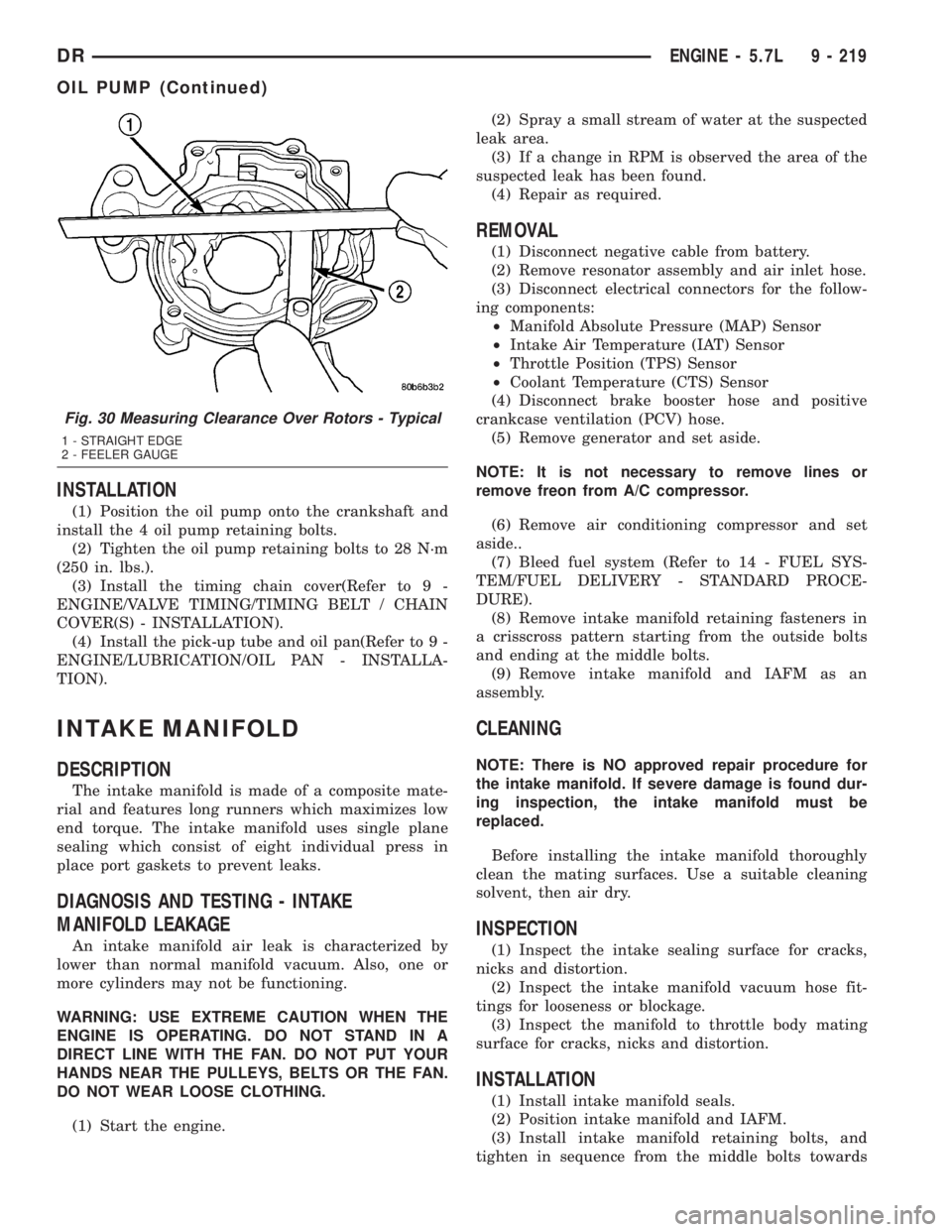
Fig. 30 Measuring Clearance Over Rotors - Typical
1 - STRAIGHT EDGE
2 - FEELER GAUGE
DRENGINE - 5.7L 9 - 219
OIL PUMP (Continued)
Page 1469 of 2895
the outside in a crisscross pattern. Torque fasteners
to 12 N´m (105 in. lbs.).
(4) Connect electrical connectors for the following
components:
²Manifold Absolute Pressure (MAP) Sensor
²Intake Air Temperature (IAT) Sensor
²Throttle Position (TPS) Sensor
²Coolant Temperature (CTS) Sensor
²Idle Air Control (IAC) Motor
(5) Install generator.
(6) Install A/C compressor.
(7) Connect Brake booster hose and Positive crank-
case ventilation (PCV) hose.
(8) Install resonator assembly and air inlet hose.
(9) Connect negative cable to battery.
EXHAUST MANIFOLD
DESCRIPTION
The exhaust manifolds are log style with a pat-
ented flow enhancing design to maximize perfor-
mance. The exhaust manifolds are made of high
silicon molybdenum cast iron. A perforated core
graphite exhaust manifold gasket is used to improve
sealing to the cylinder head. The exhaust manifolds
are covered by a three layer laminated heat shield
for thermal protection and noise reduction. The heat
shields are fastened with a torque prevailing nut
that is backed off slightly to allow for the thermal
expansion of the exhaust manifold.
OPERATION
The exhaust manifolds collect the engine exhaust
exiting the combustion chambers, then channels the
exhaust gases to the exhaust pipes attached to the
manifolds.
REMOVAL
EXHAUST MANIFOLD
(1) Disconnect negative battery cable.
(2) Raise vehicle.
(3) Remove exhaust pipe to manifold bolts.
(4) Lower vehicle.
(5) Install engine support fixture special tool
#8534.
(6) Raise engine enough to remove manifolds.
CAUTION: Do not damage engine harness while
raising the engine.
(7) Remove heat shield.
(8) Remove manifold bolts.
(9) Remove manifold and gasket.
CLEANING
Clean mating surfaces on cylinder head and mani-
fold. Wash with solvent and blow dry with com-
pressed air.
INSPECTION
Inspect manifold for cracks.
Inspect mating surfaces of manifold for flatness
with a straight edge. Gasket surfaces must be flat
within 0.2 mm per 300 mm (0.008 inch per foot).
INSTALLATION
EXHAUST MANIFOLD
(1) Install manifold gasket and manifold.
(2) Install manifold bolts and tighten to 25 N´m
(18 ft. lbs.).
(3) Install heat shield and tighten nuts to 15 N´m
(11 ft. lbs.).
(4) Lower engine.
CAUTION: Do not damage engine harness while
lowering the engine.
(5) Remove engine support fixture from engine.
(6) Raise vehicle.
(7) Tighten right and left side engine mount
through bolts.
(8) Install exhaust flange to pipe bolts.
(9) Lower vehicle.
(10) Connect negative battery cable.
TIMING/CHAIN COVER
REMOVAL
(1) Disconnect the battery negative cable.
(2) Remove air cleaner assembly.
(3) Drain cooling system.
(4) Remove accessory drive belt.
(5) Remove fan and fan drive assembly (Refer to 7
- COOLING/ENGINE/FAN DRIVE VISCOUS
CLUTCH - REMOVAL).
(6) Remove coolant bottle and washer bottle.
(7) Remove fan shroud.
NOTE: It is not necessary to disconnect A/C lines or
discharge freon.
(8) Remove A/C compressor and set aside.
(9) Remove the generator.
(10) Remove upper radiator hose.
(11) Disconnect both heater hoses at timing cover.
(12) Disconnect lower radiator hose at engine.
(13) Remove accessory drive belt tensioner and
both idler pulleys.
9 - 220 ENGINE - 5.7LDR
INTAKE MANIFOLD (Continued)
Page 1473 of 2895
HYDRAULIC LIFTERS
DIAGNOSIS AND TESTINGÐHYDRAULIC
TAPPETS...........................258
REMOVAL............................259
CLEANING...........................260
INSTALLATION........................260
PISTON & CONNECTING ROD
DESCRIPTION........................260
STANDARD PROCEDURE - PISTON FITTING . 260
REMOVAL............................261
CLEANING...........................261
INSPECTION.........................261
INSTALLATION........................261
PISTON RINGS
STANDARD PROCEDURE - PISTON RING
FITTING............................262
VIBRATION DAMPER
REMOVAL............................263
INSTALLATION........................263
FRONT MOUNT
REMOVAL............................264
INSTALLATION........................265
REAR MOUNT
REMOVAL............................266
INSTALLATION........................267
LUBRICATION
DESCRIPTION........................267
OPERATION..........................267
DIAGNOSIS AND TESTING
DIAGNOSIS AND TESTINGÐENGINE OIL
LEAKS.............................269
DIAGNOSIS AND TESTINGÐENGINE OIL
PRESSURE.........................269
OIL
STANDARD PROCEDURE - ENGINE OIL....269
OIL FILTER
REMOVAL............................270INSTALLATION........................270
OIL PAN
REMOVAL............................270
CLEANING...........................270
INSPECTION.........................271
INSTALLATION........................271
OIL PUMP
REMOVAL............................272
DISASSEMBLY........................272
INSPECTION.........................272
ASSEMBLY...........................274
INSTALLATION........................274
INTAKE MANIFOLD
DESCRIPTION........................274
OPERATION..........................274
DIAGNOSIS AND TESTINGÐINTAKE
MANIFOLD LEAKAGE.................274
REMOVAL............................275
CLEANING...........................275
INSPECTION.........................275
INSTALLATION........................275
EXHAUST MANIFOLD
DESCRIPTION........................277
OPERATION..........................277
REMOVAL............................277
CLEANING...........................277
INSPECTION.........................277
INSTALLATION........................277
TIMING BELT / CHAIN COVER(S)
REMOVAL............................278
INSTALLATION........................278
TIMING BELT/CHAIN AND SPROCKETS
REMOVAL............................279
INSPECTIONÐMEASURING TIMING CHAIN
STRETCH..........................279
INSTALLATION........................279
ENGINE - 5.9L
DESCRIPTION
The 5.9 Liter (360 CID) eight-cylinder engine is a
V-Type lightweight, single cam, overhead valve
engine with hydraulic roller tappets. This engine is
designed for unleaded fuel.
The engine lubrication system consists of a rotor
type oil pump and a full flow oil filter.
The cylinders are numbered from front to rear; 1,
3, 5, 7 on the left bank and 2, 4, 6, 8 on the right
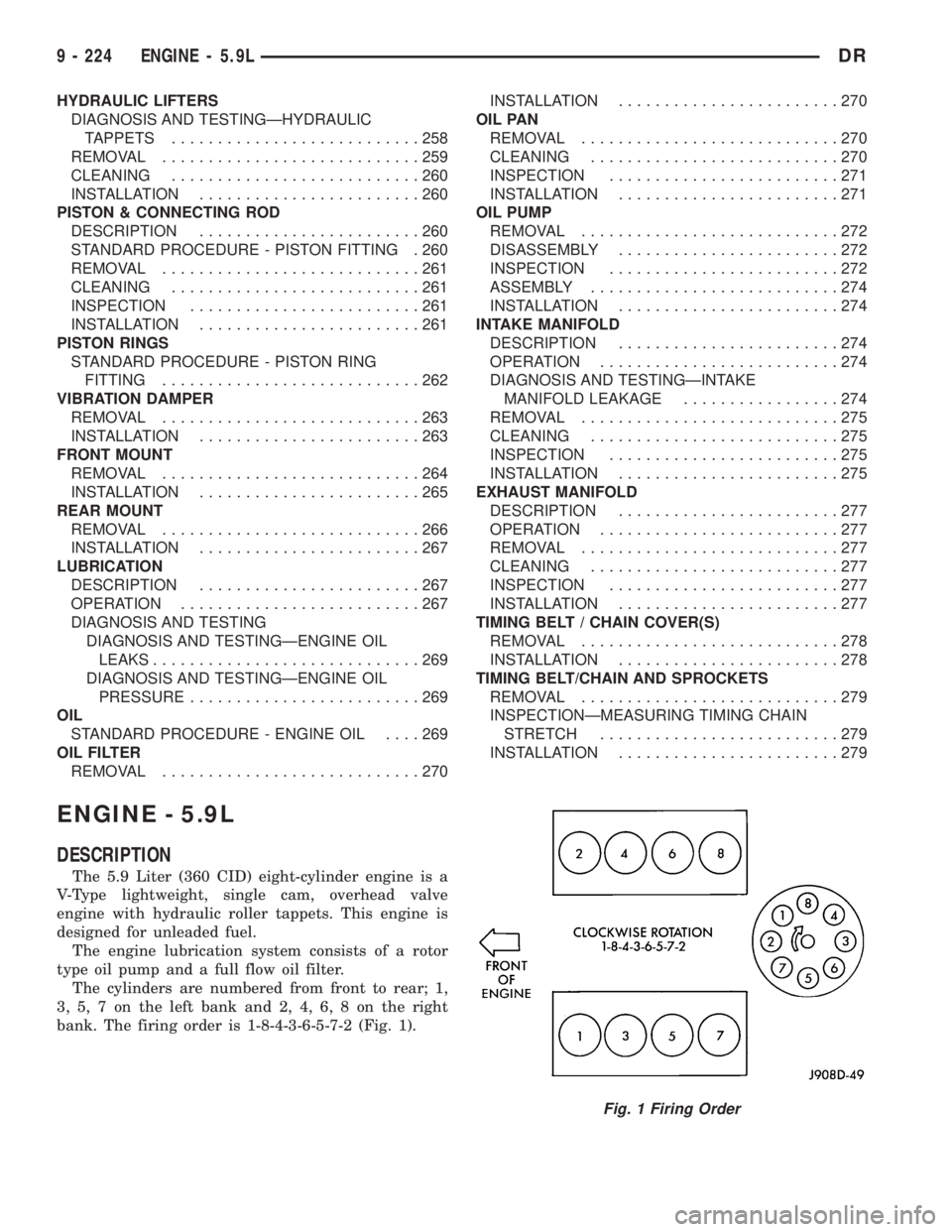
bank. The firing order is 1-8-4-3-6-5-7-2 (Fig. 1).
Fig. 1 Firing Order
9 - 224 ENGINE - 5.9LDR
Page 1474 of 2895
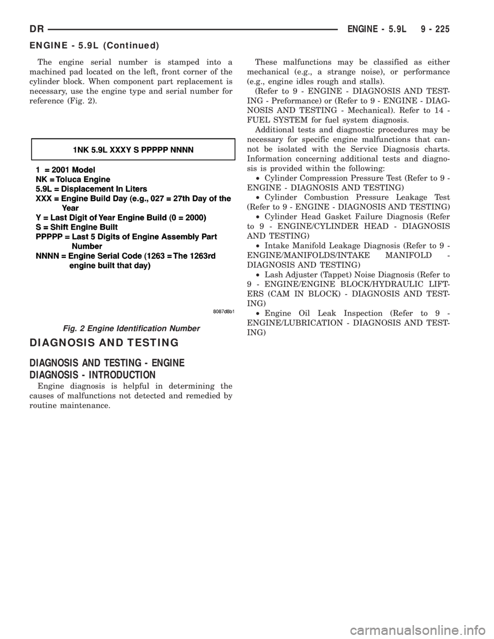
The engine serial number is stamped into a
machined pad located on the left, front corner of the
cylinder block. When component part replacement is
necessary, use the engine type and serial number for
reference (Fig. 2).
DIAGNOSIS AND TESTING
DIAGNOSIS AND TESTING - ENGINE
DIAGNOSIS - INTRODUCTION
Engine diagnosis is helpful in determining the
causes of malfunctions not detected and remedied by
routine maintenance.These malfunctions may be classified as either
mechanical (e.g., a strange noise), or performance
(e.g., engine idles rough and stalls).
(Refer to 9 - ENGINE - DIAGNOSIS AND TEST-
ING - Preformance) or (Refer to 9 - ENGINE - DIAG-
NOSIS AND TESTING - Mechanical). Refer to 14 -
FUEL SYSTEM for fuel system diagnosis.
Additional tests and diagnostic procedures may be
necessary for specific engine malfunctions that can-
not be isolated with the Service Diagnosis charts.
Information concerning additional tests and diagno-
sis is provided within the following:
²Cylinder Compression Pressure Test (Refer to 9 -
ENGINE - DIAGNOSIS AND TESTING)
²Cylinder Combustion Pressure Leakage Test
(Refer to 9 - ENGINE - DIAGNOSIS AND TESTING)
²Cylinder Head Gasket Failure Diagnosis (Refer
to 9 - ENGINE/CYLINDER HEAD - DIAGNOSIS
AND TESTING)
²Intake Manifold Leakage Diagnosis (Refer to 9 -
ENGINE/MANIFOLDS/INTAKE MANIFOLD -
DIAGNOSIS AND TESTING)
²Lash Adjuster (Tappet) Noise Diagnosis (Refer to
9 - ENGINE/ENGINE BLOCK/HYDRAULIC LIFT-
ERS (CAM IN BLOCK) - DIAGNOSIS AND TEST-
ING)
²Engine Oil Leak Inspection (Refer to 9 -
ENGINE/LUBRICATION - DIAGNOSIS AND TEST-
ING)
Fig. 2 Engine Identification Number
DRENGINE - 5.9L 9 - 225
ENGINE - 5.9L (Continued)
Page 1476 of 2895
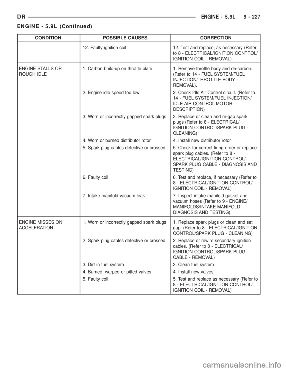
CONDITION POSSIBLE CAUSES CORRECTION
12. Faulty ignition coil 12. Test and replace, as necessary (Refer
to 8 - ELECTRICAL/IGNITION CONTROL/
IGNITION COIL - REMOVAL).
ENGINE STALLS OR
ROUGH IDLE1. Carbon build-up on throttle plate 1. Remove throttle body and de-carbon.
(Refer to 14 - FUEL SYSTEM/FUEL
INJECTION/THROTTLE BODY -
REMOVAL).
2. Engine idle speed too low 2. Check Idle Air Control circuit. (Refer to
14 - FUEL SYSTEM/FUEL INJECTION/
IDLE AIR CONTROL MOTOR -
DESCRIPTION)
3. Worn or incorrectly gapped spark plugs 3. Replace or clean and re-gap spark
plugs (Refer to 8 - ELECTRICAL/
IGNITION CONTROL/SPARK PLUG -
CLEANING)
4. Worn or burned distributor rotor 4. Install new distributor rotor
5. Spark plug cables defective or crossed 5. Check for correct firing order or replace
spark plug cables. (Refer to 8 -
ELECTRICAL/IGNITION CONTROL/
SPARK PLUG CABLE - DIAGNOSIS AND
TESTING)
6. Faulty coil 6. Test and replace, if necessary (Refer to
8 - ELECTRICAL/IGNITION CONTROL/
IGNITION COIL - REMOVAL)
7. Intake manifold vacuum leak 7. Inspect intake manifold gasket and
vacuum hoses (Refer to 9 - ENGINE/
MANIFOLDS/INTAKE MANIFOLD -
DIAGNOSIS AND TESTING).
ENGINE MISSES ON
ACCELERATION1. Worn or incorrectly gapped spark plugs 1. Replace spark plugs or clean and set
gap. (Refer to 8 - ELECTRICAL/IGNITION
CONTROL/SPARK PLUG - CLEANING)
2. Spark plug cables defective or crossed 2. Replace or rewire secondary ignition
cables. (Refer to 8 - ELECTRICAL/
IGNITION CONTROL/SPARK PLUG
CABLE - REMOVAL)
3. Dirt in fuel system 3. Clean fuel system
4. Burned, warped or pitted valves 4. Install new valves
5. Faulty coil 5. Test and replace as necessary (Refer to
8 - ELECTRICAL/IGNITION CONTROL/
IGNITION COIL - REMOVAL)
DRENGINE - 5.9L 9 - 227
ENGINE - 5.9L (Continued)
Page 1482 of 2895
(1) Perform the Fuel Pressure Release Procedure
(Refer to 14 - FUEL SYSTEM/FUEL DELIVERY -
STANDARD PROCEDURE).
(2) Disconnect the negative cable(s) from the bat-
tery.
(3) Inspect air cleaner, induction system, and
intake manifold to ensure system is dry and clear of
foreign material.
(4) Place a shop towel around the spark plugs to
catch any fluid that may possibly be under pressure
in the cylinder head. Remove the spark plugs.
(5) With all spark plugs removed, rotate the crank-
shaft using a breaker bar and socket.
(6) Identify the fluid in the cylinders (coolant, fuel,
oil, etc.).
(7) Be sure all fluid has been removed from the
cylinders.
(8) Repair engine or components as necessary to
prevent this problem from occurring again.
(9) Squirt a small amount of engine oil into the
cylinders to lubricate the walls. This will prevent
damage on restart.
(10) Install new spark plugs. Tighten the spark
plugs to 41 N´m (30 ft. lbs.) torque.
(11) Drain engine oil. Remove and discard the oil
filter.
(12) Install the drain plug. Tighten the plug to 34
N´m (25 ft. lbs.) torque.
(13) Install a new oil filter.
(14) Fill engine crankcase with the specified
amount and grade of oil. (Refer to LUBRICATION &
MAINTENANCE - SPECIFICATIONS).
(15) Connect the negative cable(s) to the battery.
(16) Start the engine and check for any leaks.
STANDARD PROCEDURE - CYLINDER BORE
HONING
Before honing, stuff plenty of clean shop towels
under the bores and over the crankshaft to keep
abrasive materials from entering the crankshaft
area.
(1) Used carefully, the Cylinder Bore Sizing Hone
C-823, equipped with 220 grit stones, is the best tool
for this job. In addition to deglazing, it will reduce
taper and out-of-round, as well as removing light
scuffing, scoring and scratches. Usually, a few strokes
will clean up a bore and maintain the required lim-
its.
CAUTION: DO NOT use rigid type hones to remove
cylinder wall glaze.
(2) Deglazing of the cylinder walls may be done if
the cylinder bore is straight and round. Use a cylin-
der surfacing hone, Honing Tool C-3501, equipped
with 280 grit stones (C-3501-3810). about 20-60strokes, depending on the bore condition, will be suf-
ficient to provide a satisfactory surface. Using honing
oil C-3501-3880, or a light honing oil, available from
major oil distributors.
CAUTION: DO NOT use engine or transmission oil,
mineral spirits, or kerosene.
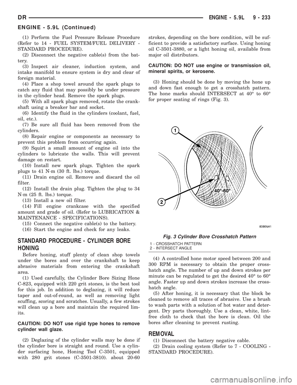
(3) Honing should be done by moving the hone up
and down fast enough to get a crosshatch pattern.
The hone marks should INTERSECT at 40É to 60É
for proper seating of rings (Fig. 3).
(4) A controlled hone motor speed between 200 and
300 RPM is necessary to obtain the proper cross-
hatch angle. The number of up and down strokes per
minute can be regulated to get the desired 40É to 60É
angle. Faster up and down strokes increase the cross-
hatch angle.
(5) After honing, it is necessary that the block be
cleaned to remove all traces of abrasive. Use a brush
to wash parts with a solution of hot water and deter-
gent. Dry parts thoroughly. Use a clean, white, lint-
free cloth to check that the bore is clean. Oil the
bores after cleaning to prevent rusting.
REMOVAL
(1) Disconnect the battery negative cable.
(2) Drain cooling system (Refer to 7 - COOLING -
STANDARD PROCEDURE).
Fig. 3 Cylinder Bore Crosshatch Pattern
1 - CROSSHATCH PATTERN
2 - INTERSECT ANGLE
DRENGINE - 5.9L 9 - 233
ENGINE - 5.9L (Continued)
Page 1483 of 2895
(3) Recover refrigerant from a/c system, if
equipped (Refer to 24 - HEATING & AIR CONDI-
TIONING/PLUMBING - STANDARD PROCEDURE).
(4) Remove the a/c condenser, if equipped (Refer to
24 - HEATING & AIR CONDITIONING/PLUMBING/
A/C CONDENSER - REMOVAL).
(5) Remove the transmission oil cooler (Refer to 7 -
COOLING/TRANSMISSION/TRANS COOLER -
REMOVAL).
(6) Remove the washer bottle from the fan shroud.
(7) Remove the viscous fan/drive (Refer to 7 -
COOLING/ENGINE/RADIATOR FAN - REMOVAL).
(8) Remove radiator (Refer to 7 - COOLING/EN-
GINE/RADIATOR - REMOVAL).
(9) Remove the upper crossmember and top core
support.
(10) Remove the accessory drive belt (Refer to 7 -
COOLING/ACCESSORY DRIVE/DRIVE BELTS -
REMOVAL).
(11) Remove the A/C compressor with the lines
attached. Secure compressor out of the way.
(12) Remove generator assembly (Refer to 8 -
ELECTRICAL/CHARGING/GENERATOR - REMOV-
AL).
(13) Remove the air cleaner resonator and duct
work as an assembly.
(14) Disconnect the throttle linkage (Refer to 14 -
FUEL SYSTEM/FUEL INJECTION/THROTTLE
CONTROL CABLE - REMOVAL).
(15) Remove throttle body (Refer to 14 - FUEL
SYSTEM/FUEL INJECTION/THROTTLE BODY -
REMOVAL).
(16) Remove the intake manifold (Refer to 9 -
ENGINE/MANIFOLDS/INTAKE MANIFOLD -
REMOVAL).
(17) Remove the distributor cap and wiring.
(18) Disconnect the heater hoses.
(19) Disconnect the power steering hoses, if
equipped.
(20) Perform the Fuel System Pressure Release
procedure (Refer to 14 - FUEL SYSTEM/FUEL
DELIVERY - STANDARD PROCEDURE).
(21) Disconnect the fuel supply line (Refer to 14 -
FUEL SYSTEM/FUEL DELIVERY/QUICK CON-
NECT FITTING - STANDARD PROCEDURE).
(22) On Manual Transmission vehicles, remove the
shift lever (Refer to 21 - TRANSMISSION/TRANS-
AXLE/MANUAL/SHIFT COVER - REMOVAL).
(23) Raise and support the vehicle on a hoist and
drain the engine oil.
(24) Remove engine front mount thru-bolt nuts.
(25) Disconnect the transmission oil cooler lines
from their retainers at the oil pan bolts.
(26) Disconnect exhaust pipe at manifolds.(27) Disconnect the starter wires. Remove starter
motor (Refer to 8 - ELECTRICAL/STARTING/
STARTER MOTOR - REMOVAL).
(28) Remove the dust shield and transmission
inspection cover.
(29) Remove drive plate to converter bolts (Auto-
matic transmission equipped vehicles).
(30) Remove transmission bell housing to engine
block bolts.
(31) Lower the vehicle.
(32) Install an engine lifting fixture.
(33) Separate engine from transmission, remove
engine from vehicle, and install engine assembly on a
repair stand.
INSTALLATION
(1) Remove engine from the repair stand and posi-
tion in the engine compartment. Position the thru-
bolt into the support cushion brackets.
(2) Install engine lifting device.
(3) Lower engine into compartment and align
engine with transmission:
²Manual Transmission: Align clutch disc assem-
bly (if disturbed). Install transmission input shaft
into clutch disc while mating engine and transmis-
sion surfaces. Install two transmission to engine
block mounting bolts finger tight.
²Automatic Transmission: Mate engine and trans-
mission and install two transmission to engine block
mounting bolts finger tight.
(4) Lower engine assembly until engine mount
through bolts rest in mount perches.
(5) Install remaining transmission to engine block
mounting bolts and tighten.
(6) Tighten engine mount through bolts.
(7) Install drive plate to torque converter bolts.
(Automatic transmission models)
(8) Install the dust shield and transmission cover.
(9) Install the starter and connect the starter
wires (Refer to 8 - ELECTRICAL/STARTING/
STARTER MOTOR - INSTALLATION).
(10) Install exhaust pipe to manifold.
(11) Install the transmission cooler line brackets to
the oil pan.
(12) Install the drain plug and tighten to 34 N´m
(25 ft. lbs.) torque.
(13) Lower the vehicle.
(14) Remove engine lifting fixture.
(15) On Manual Transmission vehicles, install the
shift lever (Refer to 21 - TRANSMISSION/TRANS-
AXLE/MANUAL/SHIFT COVER - INSTALLATION).
(16) Connect the fuel supply line (Refer to 14 -
FUEL SYSTEM/FUEL DELIVERY/QUICK CON-
NECT FITTING - STANDARD PROCEDURE).
(17) Connect the power steering hoses, if equipped.
(18) Connect the heater hoses.
9 - 234 ENGINE - 5.9LDR
ENGINE - 5.9L (Continued)
Page 1484 of 2895
(19) Install the distributor cap and wiring.
(20) Install the intake manifold (Refer to 9 -
ENGINE/MANIFOLDS/INTAKE MANIFOLD -
INSTALLATION).
(21) Using a new gasket, install throttle body
(Refer to 14 - FUEL SYSTEM/FUEL INJECTION/
THROTTLE BODY - INSTALLATION).
(22) Connect the throttle linkage (Refer to 14 -
FUEL SYSTEM/FUEL INJECTION/THROTTLE
CONTROL CABLE - INSTALLATION).
(23) Install the air cleaner resonator and duct
work..
(24) Install the generator and wire connections
(Refer to 8 - ELECTRICAL/CHARGING/GENERA-
TOR - INSTALLATION).
(25) Install a/c compressor and lines (Refer to 24 -
HEATING & AIR CONDITIONING/PLUMBING/A/C
COMPRESSOR - INSTALLATION).
(26) Install the accessory drive belt (Refer to 7 -
COOLING/ACCESSORY DRIVE/DRIVE BELTS -
INSTALLATION).
(27) Install upper radiator support crossmember.
(28) Install radiator (Refer to 7 - COOLING/EN-
GINE/RADIATOR - INSTALLATION).
(29) Connect the radiator lower hose.
(30) Connect the transmission oil cooler lines to
the radiator.
(31) Install the fan shroud.
(32) Install the fan (Refer to 7 - COOLING/EN-
GINE/RADIATOR FAN - INSTALLATION).
(33) Connect the radiator upper hose.
(34) Install the washer bottle.
(35) Install the transmission oil cooler (Refer to 7 -
COOLING/TRANSMISSION/TRANS COOLER -
INSTALLATION).
(36) Connect the transmission cooler lines.
(37) If equipped, install the condenser (Refer to 24
- HEATING & AIR CONDITIONING/PLUMBING/
A/C CONDENSER - INSTALLATION).
(38) Evacuate and charge the air conditioning sys-
tem, if equipped (Refer to 24 - HEATING & AIR
CONDITIONING/PLUMBING - STANDARD PRO-
CEDURE).
(39) Add engine oil to crankcase (Refer to LUBRI-
CATION & MAINTENANCE/FLUID TYPES - SPEC-
IFICATIONS).
(40) Fill cooling system (Refer to 7 - COOLING -
STANDARD PROCEDURE).
(41) Connect battery negative cable.
(42) Start engine and inspect for leaks.
(43) Road test vehicle.SPECIFICATIONS
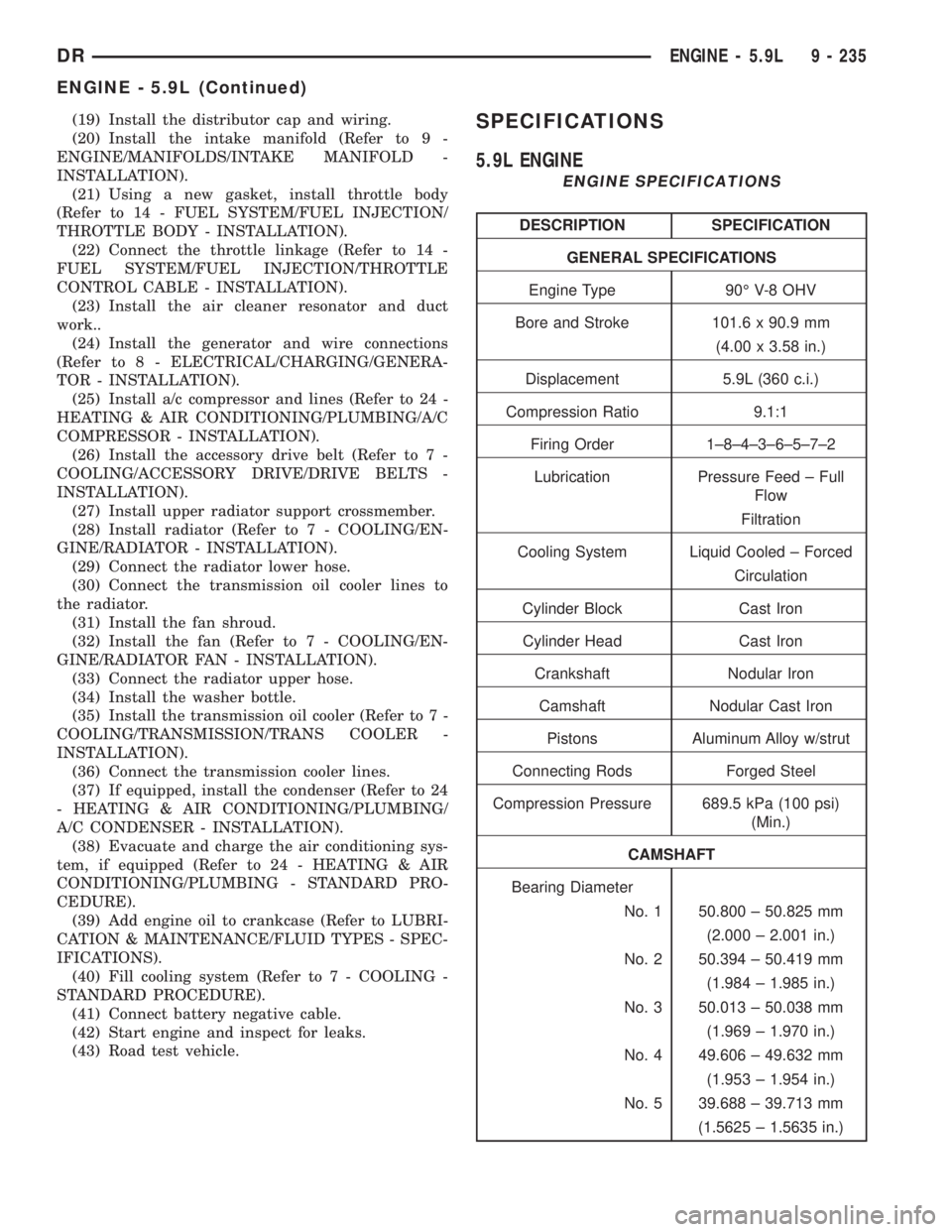
5.9L ENGINE
ENGINE SPECIFICATIONS
DESCRIPTION SPECIFICATION
GENERAL SPECIFICATIONS
Engine Type 90É V-8 OHV
Bore and Stroke 101.6 x 90.9 mm
(4.00 x 3.58 in.)
Displacement 5.9L (360 c.i.)
Compression Ratio 9.1:1
Firing Order 1±8±4±3±6±5±7±2
Lubrication Pressure Feed ± Full
Flow
Filtration
Cooling System Liquid Cooled ± Forced
Circulation
Cylinder Block Cast Iron
Cylinder Head Cast Iron
Crankshaft Nodular Iron
Camshaft Nodular Cast Iron
Pistons Aluminum Alloy w/strut
Connecting Rods Forged Steel
Compression Pressure 689.5 kPa (100 psi)
(Min.)
CAMSHAFT
Bearing Diameter
No. 1 50.800 ± 50.825 mm
(2.000 ± 2.001 in.)
No. 2 50.394 ± 50.419 mm
(1.984 ± 1.985 in.)
No. 3 50.013 ± 50.038 mm
(1.969 ± 1.970 in.)
No. 4 49.606 ± 49.632 mm
(1.953 ± 1.954 in.)
No. 5 39.688 ± 39.713 mm
(1.5625 ± 1.5635 in.)
DRENGINE - 5.9L 9 - 235
ENGINE - 5.9L (Continued)
Page 1488 of 2895
OS-US Item Identification Location of
.127 mm adjacent to
two
(.005 in.) 3/89tapped
holes on
each
end of
cylinder
head.
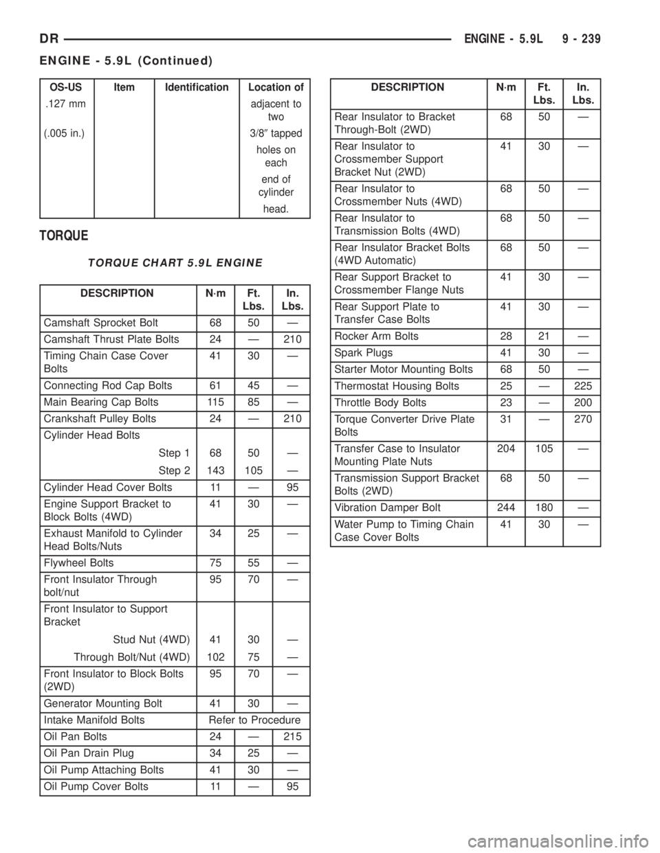
TORQUE
TORQUE CHART 5.9L ENGINE
DESCRIPTION N´m Ft.
Lbs.In.
Lbs.
Camshaft Sprocket Bolt 68 50 Ð
Camshaft Thrust Plate Bolts 24 Ð 210
Timing Chain Case Cover
Bolts41 30 Ð
Connecting Rod Cap Bolts 61 45 Ð
Main Bearing Cap Bolts 115 85 Ð
Crankshaft Pulley Bolts 24 Ð 210
Cylinder Head Bolts
Step 1 68 50 Ð
Step 2 143 105 Ð
Cylinder Head Cover Bolts 11 Ð 95
Engine Support Bracket to
Block Bolts (4WD)41 30 Ð
Exhaust Manifold to Cylinder
Head Bolts/Nuts34 25 Ð
Flywheel Bolts 75 55 Ð
Front Insulator Through
bolt/nut95 70 Ð
Front Insulator to Support
Bracket
Stud Nut (4WD) 41 30 Ð
Through Bolt/Nut (4WD) 102 75 Ð
Front Insulator to Block Bolts
(2WD)95 70 Ð
Generator Mounting Bolt 41 30 Ð
Intake Manifold Bolts Refer to Procedure
Oil Pan Bolts 24 Ð 215
Oil Pan Drain Plug 34 25 Ð
Oil Pump Attaching Bolts 41 30 Ð
Oil Pump Cover Bolts 11 Ð 95
DESCRIPTION N´m Ft.
Lbs.In.
Lbs.
Rear Insulator to Bracket
Through-Bolt (2WD)68 50 Ð
Rear Insulator to
Crossmember Support
Bracket Nut (2WD)41 30 Ð
Rear Insulator to
Crossmember Nuts (4WD)68 50 Ð
Rear Insulator to
Transmission Bolts (4WD)68 50 Ð
Rear Insulator Bracket Bolts
(4WD Automatic)68 50 Ð
Rear Support Bracket to
Crossmember Flange Nuts41 30 Ð
Rear Support Plate to
Transfer Case Bolts41 30 Ð
Rocker Arm Bolts 28 21 Ð
Spark Plugs 41 30 Ð
Starter Motor Mounting Bolts 68 50 Ð
Thermostat Housing Bolts 25 Ð 225
Throttle Body Bolts 23 Ð 200
Torque Converter Drive Plate
Bolts31 Ð 270
Transfer Case to Insulator
Mounting Plate Nuts204 105 Ð
Transmission Support Bracket
Bolts (2WD)68 50 Ð
Vibration Damper Bolt 244 180 Ð
Water Pump to Timing Chain
Case Cover Bolts41 30 Ð
DRENGINE - 5.9L 9 - 239
ENGINE - 5.9L (Continued)
Page 1493 of 2895
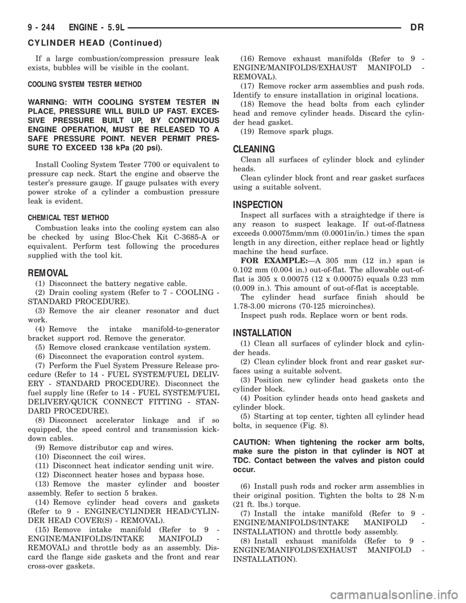
If a large combustion/compression pressure leak
exists, bubbles will be visible in the coolant.
COOLING SYSTEM TESTER METHOD
WARNING: WITH COOLING SYSTEM TESTER IN
PLACE, PRESSURE WILL BUILD UP FAST. EXCES-
SIVE PRESSURE BUILT UP, BY CONTINUOUS
ENGINE OPERATION, MUST BE RELEASED TO A
SAFE PRESSURE POINT. NEVER PERMIT PRES-
SURE TO EXCEED 138 kPa (20 psi).
Install Cooling System Tester 7700 or equivalent to
pressure cap neck. Start the engine and observe the
tester's pressure gauge. If gauge pulsates with every
power stroke of a cylinder a combustion pressure
leak is evident.
CHEMICAL TEST METHOD
Combustion leaks into the cooling system can also
be checked by using Bloc-Chek Kit C-3685-A or
equivalent. Perform test following the procedures
supplied with the tool kit.
REMOVAL
(1) Disconnect the battery negative cable.
(2) Drain cooling system (Refer to 7 - COOLING -
STANDARD PROCEDURE).
(3) Remove the air cleaner resonator and duct
work.
(4) Remove the intake manifold-to-generator
bracket support rod. Remove the generator.
(5) Remove closed crankcase ventilation system.
(6) Disconnect the evaporation control system.
(7) Perform the Fuel System Pressure Release pro-
cedure (Refer to 14 - FUEL SYSTEM/FUEL DELIV-
ERY - STANDARD PROCEDURE). Disconnect the
fuel supply line (Refer to 14 - FUEL SYSTEM/FUEL
DELIVERY/QUICK CONNECT FITTING - STAN-
DARD PROCEDURE).
(8) Disconnect accelerator linkage and if so
equipped, the speed control and transmission kick-
down cables.
(9) Remove distributor cap and wires.
(10) Disconnect the coil wires.
(11) Disconnect heat indicator sending unit wire.
(12) Disconnect heater hoses and bypass hose.
(13) Remove the master cylinder and booster
assembly. Refer to section 5 brakes.
(14) Remove cylinder head covers and gaskets
(Refer to 9 - ENGINE/CYLINDER HEAD/CYLIN-
DER HEAD COVER(S) - REMOVAL).
(15) Remove intake manifold (Refer to 9 -
ENGINE/MANIFOLDS/INTAKE MANIFOLD -
REMOVAL) and throttle body as an assembly. Dis-
card the flange side gaskets and the front and rear
cross-over gaskets.(16) Remove exhaust manifolds (Refer to 9 -
ENGINE/MANIFOLDS/EXHAUST MANIFOLD -
REMOVAL).
(17) Remove rocker arm assemblies and push rods.
Identify to ensure installation in original locations.
(18) Remove the head bolts from each cylinder
head and remove cylinder heads. Discard the cylin-
der head gasket.
(19) Remove spark plugs.
CLEANING
Clean all surfaces of cylinder block and cylinder
heads.
Clean cylinder block front and rear gasket surfaces
using a suitable solvent.
INSPECTION
Inspect all surfaces with a straightedge if there is
any reason to suspect leakage. If out-of-flatness
exceeds 0.00075mm/mm (0.0001in/in.) times the span
length in any direction, either replace head or lightly
machine the head surface.
FOR EXAMPLE:ÐA 305 mm (12 in.) span is
0.102 mm (0.004 in.) out-of-flat. The allowable out-of-
flat is 305 x 0.00075 (12 x 0.00075) equals 0.23 mm
(0.009 in.). This amount of out-of-flat is acceptable.
The cylinder head surface finish should be
1.78-3.00 microns (70-125 microinches).
Inspect push rods. Replace worn or bent rods.
INSTALLATION
(1) Clean all surfaces of cylinder block and cylin-
der heads.
(2) Clean cylinder block front and rear gasket sur-
faces using a suitable solvent.
(3) Position new cylinder head gaskets onto the
cylinder block.
(4) Position cylinder heads onto head gaskets and
cylinder block.
(5) Starting at top center, tighten all cylinder head
bolts, in sequence (Fig. 8).
CAUTION: When tightening the rocker arm bolts,
make sure the piston in that cylinder is NOT at
TDC. Contact between the valves and piston could
occur.
(6) Install push rods and rocker arm assemblies in
their original position. Tighten the bolts to 28 N´m
(21 ft. lbs.) torque.
(7) Install the intake manifold (Refer to 9 -
ENGINE/MANIFOLDS/INTAKE MANIFOLD -
INSTALLATION) and throttle body assembly.
(8) Install exhaust manifolds (Refer to 9 -
ENGINE/MANIFOLDS/EXHAUST MANIFOLD -
INSTALLATION).
9 - 244 ENGINE - 5.9LDR
CYLINDER HEAD (Continued)