Engine Intake Manifold DODGE RAM 2003 Service Owners Manual
[x] Cancel search | Manufacturer: DODGE, Model Year: 2003, Model line: RAM, Model: DODGE RAM 2003Pages: 2895, PDF Size: 83.15 MB
Page 1534 of 2895
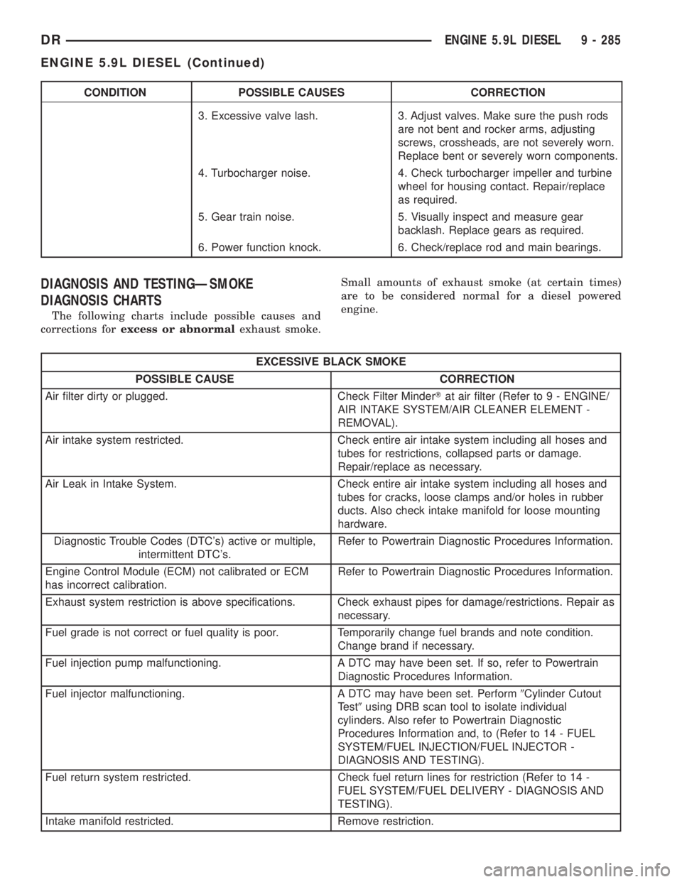
CONDITION POSSIBLE CAUSES CORRECTION
3. Excessive valve lash. 3. Adjust valves. Make sure the push rods
are not bent and rocker arms, adjusting
screws, crossheads, are not severely worn.
Replace bent or severely worn components.
4. Turbocharger noise. 4. Check turbocharger impeller and turbine
wheel for housing contact. Repair/replace
as required.
5. Gear train noise. 5. Visually inspect and measure gear
backlash. Replace gears as required.
6. Power function knock. 6. Check/replace rod and main bearings.
DIAGNOSIS AND TESTINGÐSMOKE
DIAGNOSIS CHARTS
The following charts include possible causes and
corrections forexcess or abnormalexhaust smoke.Small amounts of exhaust smoke (at certain times)
are to be considered normal for a diesel powered
engine.
EXCESSIVE BLACK SMOKE
POSSIBLE CAUSE CORRECTION
Air filter dirty or plugged. Check Filter MinderTat air filter (Refer to 9 - ENGINE/
AIR INTAKE SYSTEM/AIR CLEANER ELEMENT -
REMOVAL).
Air intake system restricted. Check entire air intake system including all hoses and
tubes for restrictions, collapsed parts or damage.
Repair/replace as necessary.
Air Leak in Intake System. Check entire air intake system including all hoses and
tubes for cracks, loose clamps and/or holes in rubber
ducts. Also check intake manifold for loose mounting
hardware.
Diagnostic Trouble Codes (DTC's) active or multiple,
intermittent DTC's.Refer to Powertrain Diagnostic Procedures Information.
Engine Control Module (ECM) not calibrated or ECM
has incorrect calibration.Refer to Powertrain Diagnostic Procedures Information.
Exhaust system restriction is above specifications. Check exhaust pipes for damage/restrictions. Repair as
necessary.
Fuel grade is not correct or fuel quality is poor. Temporarily change fuel brands and note condition.
Change brand if necessary.
Fuel injection pump malfunctioning. A DTC may have been set. If so, refer to Powertrain
Diagnostic Procedures Information.
Fuel injector malfunctioning. A DTC may have been set. Perform9Cylinder Cutout
Test9using DRB scan tool to isolate individual
cylinders. Also refer to Powertrain Diagnostic
Procedures Information and, to (Refer to 14 - FUEL
SYSTEM/FUEL INJECTION/FUEL INJECTOR -
DIAGNOSIS AND TESTING).
Fuel return system restricted. Check fuel return lines for restriction (Refer to 14 -
FUEL SYSTEM/FUEL DELIVERY - DIAGNOSIS AND
TESTING).
Intake manifold restricted. Remove restriction.
DRENGINE 5.9L DIESEL 9 - 285
ENGINE 5.9L DIESEL (Continued)
Page 1535 of 2895
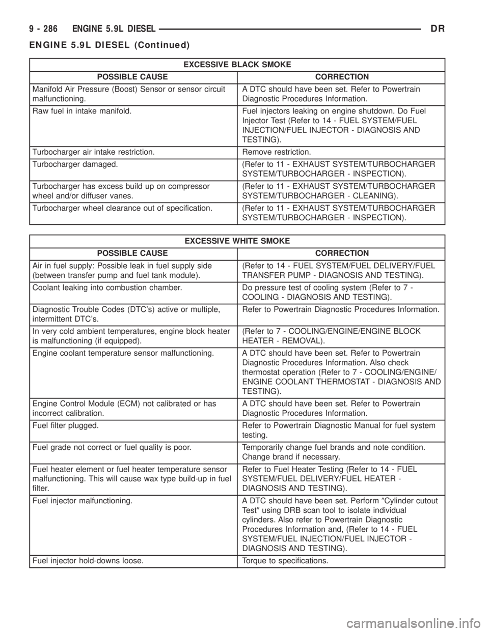
EXCESSIVE BLACK SMOKE
POSSIBLE CAUSE CORRECTION
Manifold Air Pressure (Boost) Sensor or sensor circuit
malfunctioning.A DTC should have been set. Refer to Powertrain
Diagnostic Procedures Information.
Raw fuel in intake manifold. Fuel injectors leaking on engine shutdown. Do Fuel
Injector Test (Refer to 14 - FUEL SYSTEM/FUEL
INJECTION/FUEL INJECTOR - DIAGNOSIS AND
TESTING).
Turbocharger air intake restriction. Remove restriction.
Turbocharger damaged. (Refer to 11 - EXHAUST SYSTEM/TURBOCHARGER
SYSTEM/TURBOCHARGER - INSPECTION).
Turbocharger has excess build up on compressor
wheel and/or diffuser vanes.(Refer to 11 - EXHAUST SYSTEM/TURBOCHARGER
SYSTEM/TURBOCHARGER - CLEANING).
Turbocharger wheel clearance out of specification. (Refer to 11 - EXHAUST SYSTEM/TURBOCHARGER
SYSTEM/TURBOCHARGER - INSPECTION).
EXCESSIVE WHITE SMOKE
POSSIBLE CAUSE CORRECTION
Air in fuel supply: Possible leak in fuel supply side
(between transfer pump and fuel tank module).(Refer to 14 - FUEL SYSTEM/FUEL DELIVERY/FUEL
TRANSFER PUMP - DIAGNOSIS AND TESTING).
Coolant leaking into combustion chamber. Do pressure test of cooling system (Refer to 7 -
COOLING - DIAGNOSIS AND TESTING).
Diagnostic Trouble Codes (DTC's) active or multiple,
intermittent DTC's.Refer to Powertrain Diagnostic Procedures Information.
In very cold ambient temperatures, engine block heater
is malfunctioning (if equipped).(Refer to 7 - COOLING/ENGINE/ENGINE BLOCK
HEATER - REMOVAL).
Engine coolant temperature sensor malfunctioning. A DTC should have been set. Refer to Powertrain
Diagnostic Procedures Information. Also check
thermostat operation (Refer to 7 - COOLING/ENGINE/
ENGINE COOLANT THERMOSTAT - DIAGNOSIS AND
TESTING).
Engine Control Module (ECM) not calibrated or has
incorrect calibration.A DTC should have been set. Refer to Powertrain
Diagnostic Procedures Information.
Fuel filter plugged. Refer to Powertrain Diagnostic Manual for fuel system
testing.
Fuel grade not correct or fuel quality is poor. Temporarily change fuel brands and note condition.
Change brand if necessary.
Fuel heater element or fuel heater temperature sensor
malfunctioning. This will cause wax type build-up in fuel
filter.Refer to Fuel Heater Testing (Refer to 14 - FUEL
SYSTEM/FUEL DELIVERY/FUEL HEATER -
DIAGNOSIS AND TESTING).
Fuel injector malfunctioning. A DTC should have been set. Perform9Cylinder cutout
Test9using DRB scan tool to isolate individual
cylinders. Also refer to Powertrain Diagnostic
Procedures Information and, (Refer to 14 - FUEL
SYSTEM/FUEL INJECTION/FUEL INJECTOR -
DIAGNOSIS AND TESTING).
Fuel injector hold-downs loose. Torque to specifications.
9 - 286 ENGINE 5.9L DIESELDR
ENGINE 5.9L DIESEL (Continued)
Page 1536 of 2895
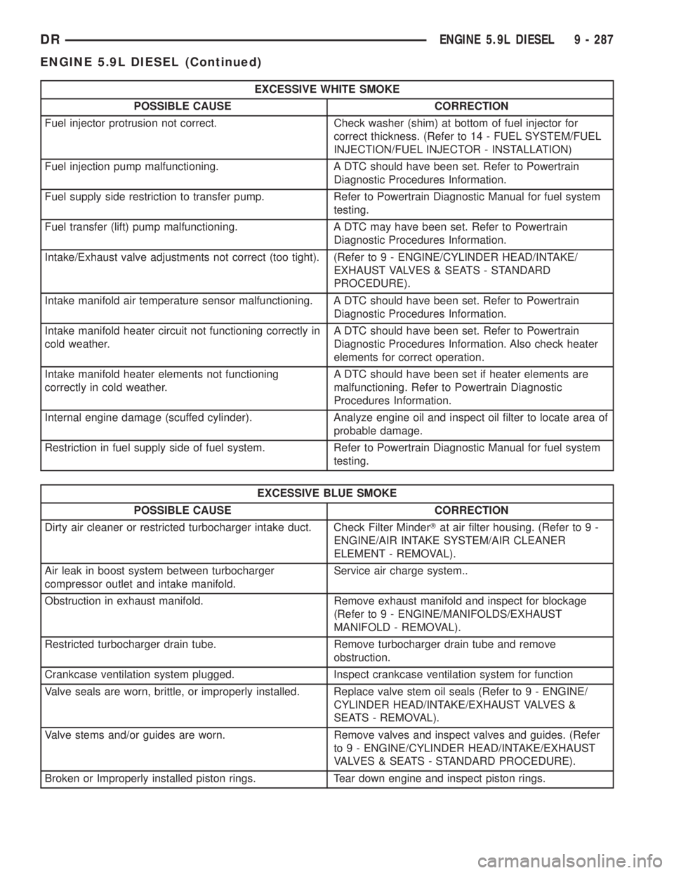
EXCESSIVE WHITE SMOKE
POSSIBLE CAUSE CORRECTION
Fuel injector protrusion not correct. Check washer (shim) at bottom of fuel injector for
correct thickness. (Refer to 14 - FUEL SYSTEM/FUEL
INJECTION/FUEL INJECTOR - INSTALLATION)
Fuel injection pump malfunctioning. A DTC should have been set. Refer to Powertrain
Diagnostic Procedures Information.
Fuel supply side restriction to transfer pump. Refer to Powertrain Diagnostic Manual for fuel system
testing.
Fuel transfer (lift) pump malfunctioning. A DTC may have been set. Refer to Powertrain
Diagnostic Procedures Information.
Intake/Exhaust valve adjustments not correct (too tight). (Refer to 9 - ENGINE/CYLINDER HEAD/INTAKE/
EXHAUST VALVES & SEATS - STANDARD
PROCEDURE).
Intake manifold air temperature sensor malfunctioning. A DTC should have been set. Refer to Powertrain
Diagnostic Procedures Information.
Intake manifold heater circuit not functioning correctly in
cold weather.A DTC should have been set. Refer to Powertrain
Diagnostic Procedures Information. Also check heater
elements for correct operation.
Intake manifold heater elements not functioning
correctly in cold weather.A DTC should have been set if heater elements are
malfunctioning. Refer to Powertrain Diagnostic
Procedures Information.
Internal engine damage (scuffed cylinder). Analyze engine oil and inspect oil filter to locate area of
probable damage.
Restriction in fuel supply side of fuel system. Refer to Powertrain Diagnostic Manual for fuel system
testing.
EXCESSIVE BLUE SMOKE
POSSIBLE CAUSE CORRECTION
Dirty air cleaner or restricted turbocharger intake duct. Check Filter MinderTat air filter housing. (Refer to 9 -
ENGINE/AIR INTAKE SYSTEM/AIR CLEANER
ELEMENT - REMOVAL).
Air leak in boost system between turbocharger
compressor outlet and intake manifold.Service air charge system..
Obstruction in exhaust manifold. Remove exhaust manifold and inspect for blockage
(Refer to 9 - ENGINE/MANIFOLDS/EXHAUST
MANIFOLD - REMOVAL).
Restricted turbocharger drain tube. Remove turbocharger drain tube and remove
obstruction.
Crankcase ventilation system plugged. Inspect crankcase ventilation system for function
Valve seals are worn, brittle, or improperly installed. Replace valve stem oil seals (Refer to 9 - ENGINE/
CYLINDER HEAD/INTAKE/EXHAUST VALVES &
SEATS - REMOVAL).
Valve stems and/or guides are worn. Remove valves and inspect valves and guides. (Refer
to 9 - ENGINE/CYLINDER HEAD/INTAKE/EXHAUST
VALVES & SEATS - STANDARD PROCEDURE).
Broken or Improperly installed piston rings. Tear down engine and inspect piston rings.
DRENGINE 5.9L DIESEL 9 - 287
ENGINE 5.9L DIESEL (Continued)
Page 1539 of 2895
²Installing an insert into the tapped hole to bring
the hole back to its original thread size.
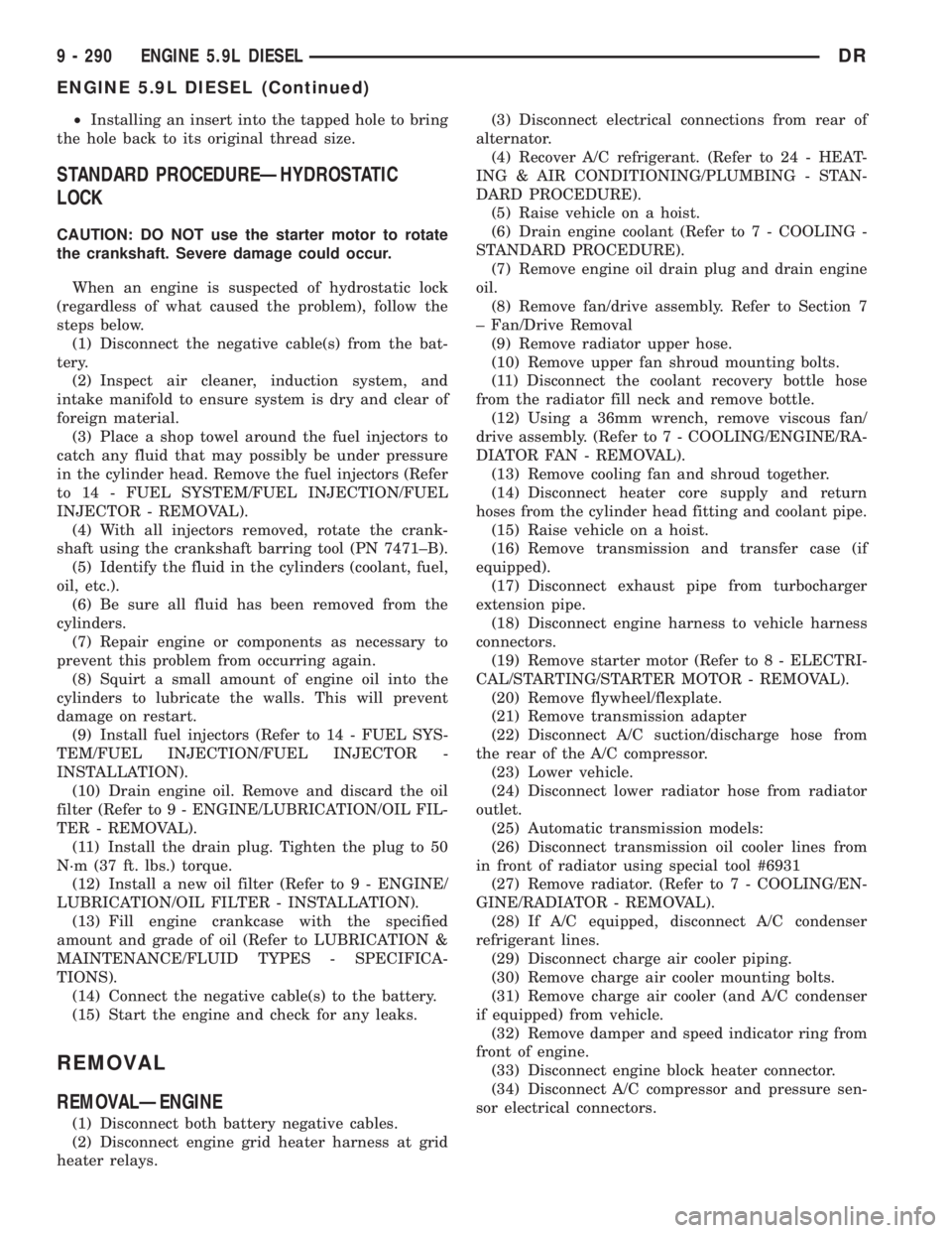
STANDARD PROCEDUREÐHYDROSTATIC
LOCK
CAUTION: DO NOT use the starter motor to rotate
the crankshaft. Severe damage could occur.
When an engine is suspected of hydrostatic lock
(regardless of what caused the problem), follow the
steps below.
(1) Disconnect the negative cable(s) from the bat-
tery.
(2) Inspect air cleaner, induction system, and
intake manifold to ensure system is dry and clear of
foreign material.
(3) Place a shop towel around the fuel injectors to
catch any fluid that may possibly be under pressure
in the cylinder head. Remove the fuel injectors (Refer
to 14 - FUEL SYSTEM/FUEL INJECTION/FUEL
INJECTOR - REMOVAL).
(4) With all injectors removed, rotate the crank-
shaft using the crankshaft barring tool (PN 7471±B).
(5) Identify the fluid in the cylinders (coolant, fuel,
oil, etc.).
(6) Be sure all fluid has been removed from the
cylinders.
(7) Repair engine or components as necessary to
prevent this problem from occurring again.
(8) Squirt a small amount of engine oil into the
cylinders to lubricate the walls. This will prevent
damage on restart.
(9) Install fuel injectors (Refer to 14 - FUEL SYS-
TEM/FUEL INJECTION/FUEL INJECTOR -
INSTALLATION).
(10) Drain engine oil. Remove and discard the oil
filter (Refer to 9 - ENGINE/LUBRICATION/OIL FIL-
TER - REMOVAL).
(11) Install the drain plug. Tighten the plug to 50
N´m (37 ft. lbs.) torque.
(12) Install a new oil filter (Refer to 9 - ENGINE/
LUBRICATION/OIL FILTER - INSTALLATION).
(13) Fill engine crankcase with the specified
amount and grade of oil (Refer to LUBRICATION &
MAINTENANCE/FLUID TYPES - SPECIFICA-
TIONS).
(14) Connect the negative cable(s) to the battery.
(15) Start the engine and check for any leaks.
REMOVAL
REMOVALÐENGINE
(1) Disconnect both battery negative cables.
(2) Disconnect engine grid heater harness at grid
heater relays.(3) Disconnect electrical connections from rear of
alternator.
(4) Recover A/C refrigerant. (Refer to 24 - HEAT-
ING & AIR CONDITIONING/PLUMBING - STAN-
DARD PROCEDURE).
(5) Raise vehicle on a hoist.
(6) Drain engine coolant (Refer to 7 - COOLING -
STANDARD PROCEDURE).
(7) Remove engine oil drain plug and drain engine
oil.
(8) Remove fan/drive assembly. Refer to Section 7
± Fan/Drive Removal
(9) Remove radiator upper hose.
(10) Remove upper fan shroud mounting bolts.
(11) Disconnect the coolant recovery bottle hose
from the radiator fill neck and remove bottle.
(12) Using a 36mm wrench, remove viscous fan/
drive assembly. (Refer to 7 - COOLING/ENGINE/RA-
DIATOR FAN - REMOVAL).
(13) Remove cooling fan and shroud together.
(14) Disconnect heater core supply and return
hoses from the cylinder head fitting and coolant pipe.
(15) Raise vehicle on a hoist.
(16) Remove transmission and transfer case (if
equipped).
(17) Disconnect exhaust pipe from turbocharger
extension pipe.
(18) Disconnect engine harness to vehicle harness
connectors.
(19) Remove starter motor (Refer to 8 - ELECTRI-
CAL/STARTING/STARTER MOTOR - REMOVAL).
(20) Remove flywheel/flexplate.
(21) Remove transmission adapter
(22) Disconnect A/C suction/discharge hose from
the rear of the A/C compressor.
(23) Lower vehicle.
(24) Disconnect lower radiator hose from radiator
outlet.
(25) Automatic transmission models:
(26) Disconnect transmission oil cooler lines from
in front of radiator using special tool #6931
(27) Remove radiator. (Refer to 7 - COOLING/EN-
GINE/RADIATOR - REMOVAL).
(28) If A/C equipped, disconnect A/C condenser
refrigerant lines.
(29) Disconnect charge air cooler piping.
(30) Remove charge air cooler mounting bolts.
(31) Remove charge air cooler (and A/C condenser
if equipped) from vehicle.
(32) Remove damper and speed indicator ring from
front of engine.
(33) Disconnect engine block heater connector.
(34) Disconnect A/C compressor and pressure sen-
sor electrical connectors.
9 - 290 ENGINE 5.9L DIESELDR
ENGINE 5.9L DIESEL (Continued)
Page 1547 of 2895
Filter Removal
(1) The housing cover is equipped with spring clips
(Fig. 6) and is hinged with plastic tabs. Unlatch clips
from top of air cleaner housing and tilt housing cover
up for cover removal.
(2) Remove air cleaner element from air cleaner
housing.
INSTALLATION
(1) Before installing new air cleaner element (fil-
ter), clean inside of air cleaner housing.
(2) Position air cleaner cover to tabs on front of air
cleaner housing. Latch spring clips to seal cover to
housing.
CYLINDER HEAD
DESCRIPTION
The cylinder head is constructed of cast iron and is
a one piece cross flow design with four valves per cyl-
inder. The arrangement of two intake and two
exhaust valves per cylinder allows for a centrally
located injector. The cylinder head also includes an
integral intake manifold, an integral thermostat
housing, and a longitudal fuel return rifle, which
exits at the rear of the head. The 24 valve design
also includes integrally cast valve guides and hard-
ened intake and exhaust valve seat inserts.
REMOVAL
(1) Disconnect battery negative cables.
(2) Raise vehicle on hoist.
(3) Drain engine coolant.
(4) Disconnect exhaust pipe from turbocharger
elbow.
(5) Lower vehicle.
(6) Disconnect air inlet temperature/pressure sen-
sor.
(7) Remove air cleaner housing and snorkel from
the vehicle. Cap off turbocharger air inlet to prevent
intrusion of dirt or foreign material.
(8) Disconnect cab heater core supply and return
hoses from the cylinder head and heater pipe.
(9) Disconnect turbocharger oil drain tube at rub-
ber hose connection. Cap off open ports to prevent
intrusion of dirt or foreign material.
(10) Disconnect turbocharger oil supply line at the
turbocharger end. Cap off open ports to prevent
intrusion of dirt or foreign material.
(11) Remove exhaust manifold-to-cylinder head
bolts, spacers, heat shield, retention straps, and cab
heater plumbing. Remove exhaust manifold and tur-
bocharger from the vehicle as an assembly.
(12) Remove cooling fan assembly.
(13) Remove accessory drive belt (Refer to 7 -
COOLING/ACCESSORY DRIVE/DRIVE BELTS -
REMOVAL).
(14) Remove cooling fan support from cylinder
block.
(15) Remove upper generator bolt, loosen lower
generator bolt, and rotate generator away from cylin-
der head.
(16) Disconnect radiator upper hose from the ther-
mostat housing.
(17) Disconnect the Intake Air Temperature, Man-
ifold Air Pressure, and Coolant Temperature sensor
connector.
(18) Remove the engine harness to cylinder head
attaching bolts and P-clips at front of head.
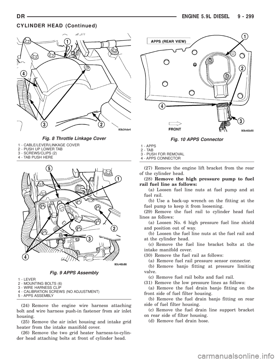
(19) Remove the throttle linkage cover (Fig. 8).
(20) Remove the six (6) accelerator pedal position
sensor assembly-to-cylinder head bracket bolts (Fig.
9) and secure the entire assembly out of the way.
Disconnect the APPS connector (Fig. 10).It is not
necessary to disconnect the cables from the
throttle control assembly.
(21) Remove the intake air grid heater wires from
the grid heater.
(22) Remove engine oil level indicator tube attach-
ing bolt at fuel filter housing bracket and inlet air
connection..
(23) Remove the charge air cooler-to-air inlet hous-
ing pipe.
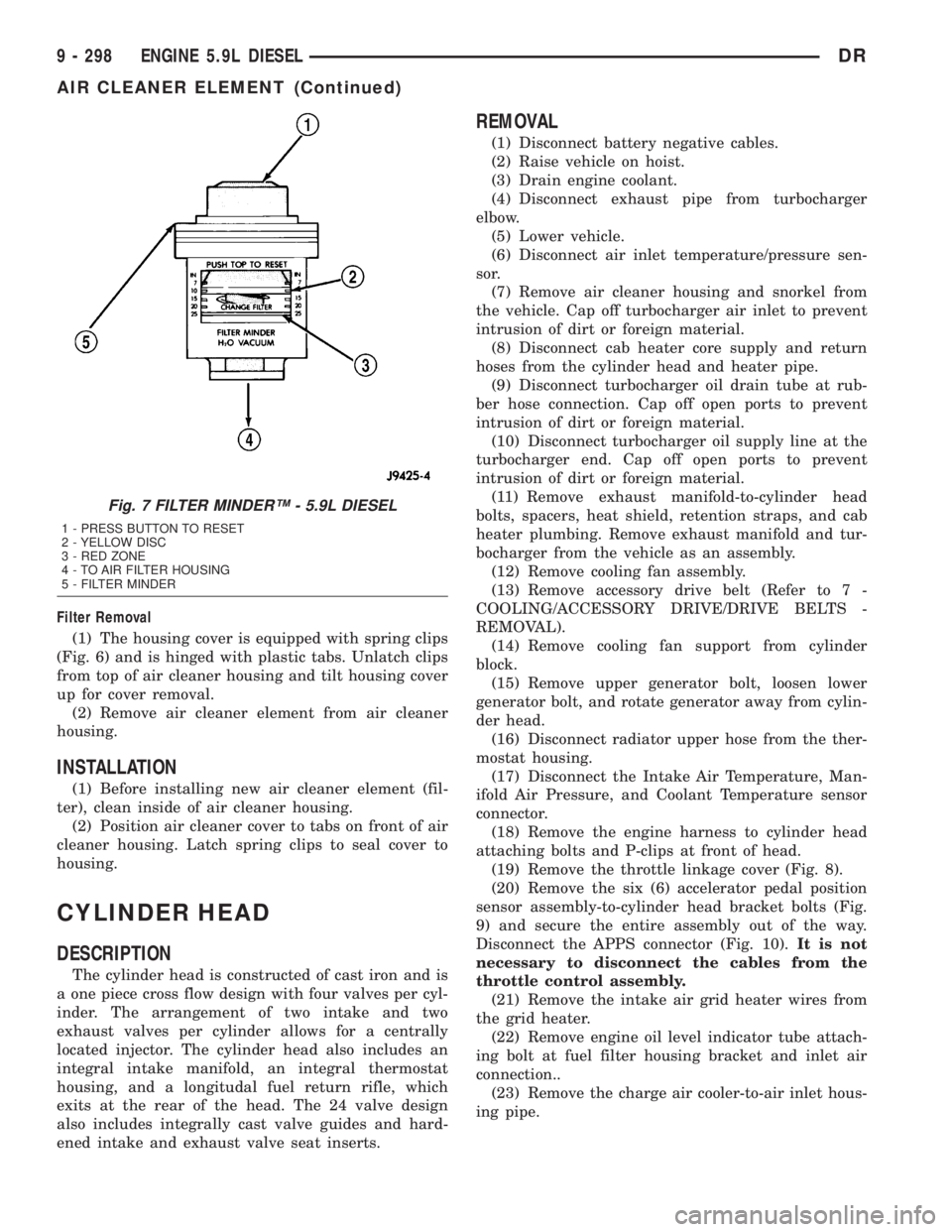
Fig. 7 FILTER MINDERŸ - 5.9L DIESEL
1 - PRESS BUTTON TO RESET
2 - YELLOW DISC
3 - RED ZONE
4 - TO AIR FILTER HOUSING
5 - FILTER MINDER
9 - 298 ENGINE 5.9L DIESELDR
AIR CLEANER ELEMENT (Continued)
Page 1548 of 2895
(24) Remove the engine wire harness attaching
bolt and wire harness push-in fastener from air inlet
housing.
(25) Remove the air inlet housing and intake grid
heater from the intake manifold cover.
(26) Remove the two grid heater harness-to-cylin-
der head attaching bolts at front of cylinder head.(27) Remove the engine lift bracket from the rear
of the cylinder head.
(28)Remove the high pressure pump to fuel
rail fuel line as follows:
(a) Loosen fuel line nuts at fuel pump and at
fuel rail.
(b) Use a back-up wrench on the fitting at the
fuel pump to keep it from loosening.
(29) Remove the fuel rail to cylinder head fuel
lines as follows:
(a) Loosen No. 6 high pressure fuel line shield
and position out of way.
(b) Loosen the fuel line nuts at the fuel rail and
at the cylinder head.
(c) Remove the fuel line bracket bolts at the
intake manifold cover.
(30) Remove the fuel rail as follows:
(a) Remove fuel rail pressure sensor connector.
(b) Remove banjo fitting at pressure limiting
valve.
(c) Remove fuel rail bolts and fuel rail.
(31) Remove the low pressure lines as follows:
(a) Remove the fuel drain banjo fitting on the
front side of fuel filter housing.
(b) Remove the fuel drain banjo fitting on rear
side of fuel filter housing.
(c) Remove the fuel drain line support bracket
on rear side of filter housing.
(d) Remove fuel drain hose.
Fig. 8 Throttle Linkage Cover
1 - CABLE/LEVER/LINKAGE COVER
2 - PUSH UP LOWER TAB
3 - SCREWS/CLIPS (2)
4 - TAB PUSH HERE
Fig. 9 APPS Assembly
1 - LEVER
2 - MOUNTING BOLTS (6)
3 - WIRE HARNESS CLIP
4 - CALIBRATION SCREWS (NO ADJUSTMENT)
5 - APPS ASSEMBLY
Fig. 10 APPS Connector
1 - APPS
2-TAB
3 - PUSH FOR REMOVAL
4 - APPS CONNECTOR
DRENGINE 5.9L DIESEL 9 - 299
CYLINDER HEAD (Continued)
Page 1556 of 2895
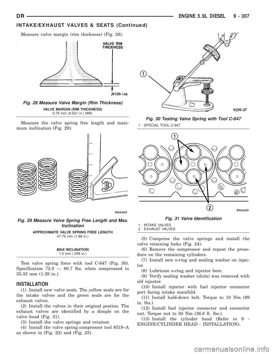
Measure valve margin (rim thickness) (Fig. 28).
Measure the valve spring free length and maxi-
mum inclination (Fig. 29).
Test valve spring force with tool C-647 (Fig. 30).
Specification 72.0 Ð 80.7 lbs. when compressed to
35.33 mm (1.39 in.).
INSTALLATION
(1) Install new valve seals. The yellow seals are for
the intake valves and the green seals are for the
exhaust valves.
(2) Install the valves in their original postion. The
exhaust valves are identified by a dimple on the
valve head (Fig. 31).
(3) Install the valve springs and retainer.
(4) Install the valve spring compressor tool 8319±A
as shown in (Fig. 22) and (Fig. 23).(5) Compress the valve springs and install the
valve retaining locks (Fig. 24).
(6) Remove the compressor and repeat the proce-
dure on the remaining cylinders.
(7) Install new o-ring and sealing washer on injec-
tor.
(8) Lubricate o-ring and injector bore.
(9) Verify sealing washer (shim) was removed with
old injector.
(10) Install injector with fuel injector connector
port facing intake manifold.
(11) Install hold-down bolt. Torque to 10 Nm (89
in. lbs.).
(12) Install fuel injector connector and connector
nut. Torque nut to 50 Nm (36.8 ft. lbs.).
(13) Install the cylinder head (Refer to 9 -
ENGINE/CYLINDER HEAD - INSTALLATION).
Fig. 28 Measure Valve Margin (Rim Thickness)
VALVE MARGIN (RIM THICKNESS)
0.79 mm (0.031 in.) MIN.
Fig. 29 Measure Valve Spring Free Length and Max.
Inclination
APPROXIMATE VALVE SPRING FREE LENGTH
47.75 mm (1.88 in.)
MAX INCLINATION
1.5 mm (.059 in.)
Fig. 30 Testing Valve Spring with Tool C-647
1 - SPECIAL TOOL C-647
Fig. 31 Valve Identification
1 - INTAKE VALVES
2 - EXHAUST VALVES
DRENGINE 5.9L DIESEL 9 - 307
INTAKE/EXHAUST VALVES & SEATS (Continued)
Page 1594 of 2895
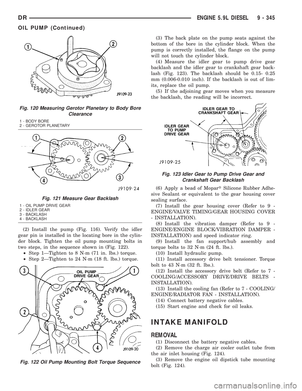
(2) Install the pump (Fig. 116). Verify the idler
gear pin is installed in the locating bore in the cylin-
der block. Tighten the oil pump mounting bolts in
two steps, in the sequence shown in (Fig. 122).
²Step 1ÐTighten to 8 N´m (71 in. lbs.) torque.
²Step 2ÐTighten to 24 N´m (18 ft. lbs.) torque.(3) The back plate on the pump seats against the
bottom of the bore in the cylinder block. When the
pump is correctly installed, the flange on the pump
will not touch the cylinder block.
(4) Measure the idler gear to pump drive gear
backlash and the idler gear to crankshaft gear back-
lash (Fig. 123). The backlash should be 0.15- 0.25
mm (0.006-0.010 inch). If the backlash is out of lim-
its, replace the oil pump.
(5) If the adjoining gear moves when you measure
the backlash, the reading will be incorrect.
(6) Apply a bead of MopartSilicone Rubber Adhe-
sive Sealant or equivalent to the gear housing cover
sealing surface.
(7) Install the gear housing cover (Refer to 9 -
ENGINE/VALVE TIMING/GEAR HOUSING COVER
- INSTALLATION).
(8) Install the vibration damper (Refer to 9 -
ENGINE/ENGINE BLOCK/VIBRATION DAMPER -
INSTALLATION) and speed indicator ring.
(9) Install the fan support/hub assembly and
torque bolts to 32 N´m (24 ft. lbs.).
(10) Install hydraulic pump.
(11) Install accessory drive belt tensioner. Torque
bolt to 43 N´m (32 ft. lbs.).
(12) Install the accessory drive belt (Refer to 7 -
COOLING/ACCESSORY DRIVE/DRIVE BELTS -
INSTALLATION).
(13) Install the cooling fan (Refer to 7 - COOLING/
ENGINE/RADIATOR FAN - INSTALLATION).
(14) Connect battery negative cables.
(15) Start engine and check for oil leaks.
INTAKE MANIFOLD
REMOVAL
(1) Disconnect the battery negative cables.
(2) Remove the charge air cooler outlet tube from
the air inlet housing (Fig. 124).
(3) Remove the engine oil dipstick tube mounting
bolt (Fig. 124).
Fig. 120 Measuring Gerotor Planetary to Body Bore
Clearance
1 - BODY BORE
2 - GEROTOR PLANETARY
Fig. 121 Measure Gear Backlash
1 - OIL PUMP DRIVE GEAR
2 - IDLER GEAR
3 - BACKLASH
4 - BACKLASH
Fig. 122 Oil Pump Mounting Bolt Torque Sequence
Fig. 123 Idler Gear to Pump Drive Gear and
Crankshaft Gear Backlash
DRENGINE 5.9L DIESEL 9 - 345
OIL PUMP (Continued)
Page 1595 of 2895
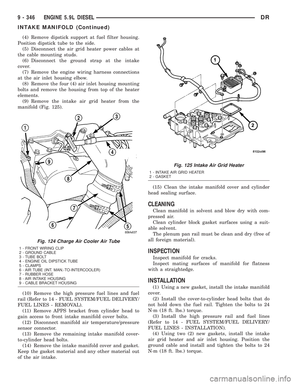
(4) Remove dipstick support at fuel filter housing.
Position dipstick tube to the side.
(5) Disconnect the air grid heater power cables at
the cable mounting studs.
(6) Disconnect the ground strap at the intake
cover.
(7) Remove the engine wiring harness connections
at the air inlet housing elbow.
(8) Remove the four (4) air inlet housing mounting
bolts and remove the housing from top of the heater
elements.
(9) Remove the intake air grid heater from the
manifold (Fig. 125).
(10) Remove the high pressure fuel lines and fuel
rail (Refer to 14 - FUEL SYSTEM/FUEL DELIVERY/
FUEL LINES - REMOVAL).
(11) Remove APPS bracket from cylinder head to
gain access to front intake manifold cover bolts.
(12) Disconnect manifold air temperature/pressure
sensor connector.
(13) Remove the remaining intake manifold cover-
to-cylinder head bolts.
(14) Remove the intake manifold cover and gasket.
Keep the gasket material and any other material out
of the air intake.(15) Clean the intake manifold cover and cylinder
head sealing surface.
CLEANING
Clean manifold in solvent and blow dry with com-
pressed air.
Clean cylinder block gasket surfaces using a suit-
able solvent.
The plenum pan rail must be clean and dry (free of
all foreign material).
INSPECTION
Inspect manifold for cracks.
Inspect mating surfaces of manifold for flatness
with a straightedge.
INSTALLATION
(1) Using a new gasket, install the intake manifold
cover.
(2) Install the cover-to-cylinder head bolts that do
not hold down the fuel rail. Tighten the bolts to 24
N´m (18 ft. lbs.) torque.
(3) Install the high pressure rail and fuel lines
(Refer to 14 - FUEL SYSTEM/FUEL DELIVERY/
FUEL LINES - INSTALLATION).
(4) Using two (2) new gaskets, install the intake
air grid heater and air inlet housing. Position the
ground cable and install and tighten the bolts to 24
N´m (18 ft. lbs.) torque.
Fig. 124 Charge Air Cooler Air Tube
1 - FRONT WIRING CLIP
2 - GROUND CABLE
3 - TUBE BOLT
4 - ENGINE OIL DIPSTICK TUBE
5 - CLAMPS
6 - AIR TUBE (INT. MAN.-TO-INTERCOOLER)
7 - RUBBER HOSE
8 - AIR INTAKE HOUSING
9 - CABLE BRACKET HOUSING
Fig. 125 Intake Air Grid Heater
1 - INTAKE AIR GRID HEATER
2 - GASKET
9 - 346 ENGINE 5.9L DIESELDR
INTAKE MANIFOLD (Continued)
Page 1596 of 2895
(5) Connect the manifold air temperature/pressure
sensor connector.
(6) Install and tighten the air intake heater power
supply nuts to 14 N´m (120 in. lbs.) torque.
(7) Install the APPS bracket. Torque fasteners to
43 N´m (32ft lbs.) torque.
(8) Install oil dipstick tube support at fuel filter
housing.
(9) Install the engine oil dipstick tube and mount-
ing bolt.
(10) Position the charge air cooler outlet tube onto
the air inlet housing. Tighten the clamps to 8 N´m
(72 in. lbs.) torque.
(11) Attach the engine wire harness to the air inlet
housing at two locations.
(12) Prime the fuel system. Refer to the fuel prim-
ing procedure in Group 14, Fuel System.
(13) Connect the battery negative cables.
EXHAUST MANIFOLD
REMOVAL
(1) Disconnect the battery negative cables.
(2) Raise vehicle on hoist.
(3) Disconnect the exhaust pipe from the turbo-
charger elbow.
(4) Lower vehicle.
(5) Disconnect the turbocharger air inlet hose.
(6) Remove air cleaner assembly.
(7) Disconnect the turbocharger oil supply line and
the oil drain tube from the turbocharger.
(8) Disconnect the charge air cooler inlet pipe from
the turbocharger.
(9) Remove the turbocharger and gasket from the
exhaust manifold.
(10) Remove the cab heater return pipe nuts from
the exhaust manifold stud. Position the tube out of
the way.
(11) Remove heat shield.
(12) Remove exhaust manifold bolt lockplates.
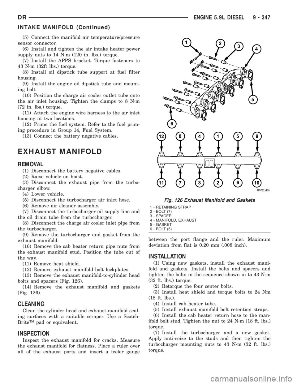
(13) Remove the exhaust manifold-to-cylinder head
bolts and spacers (Fig. 126).
(14) Remove the exhaust manifold and gaskets
(Fig. 126).
CLEANING
Clean the cylinder head and exhaust manifold seal-
ing surfaces with a suitable scraper. Use a Scotch-
BriteŸ pad or equivalent.
INSPECTION
Inspect the exhaust manifold for cracks. Measure
the exhaust manifold for flatness. Place a ruler over
all of the exhaust ports and insert a feeler gaugebetween the port flange and the ruler. Maximum
deviation from flat is 0.20 mm (.008 inch).
INSTALLATION
(1) Using new gaskets, install the exhaust mani-
fold and gaskets. Install the bolts and spacers and
tighten the bolts in the sequence shown in to 43 N´m
(32 ft. lbs.) torque.
(2) Retorque the four center bolts.
(3) Install heat shield and torque bolts to 24 Nm
(18 ft. lbs.).
(4) Install cab heater tube.
(5) Install exhaust manifold bolt retention straps.
(6) Install the cab heater return hose to the man-
ifold bolt stud. Tighten the nut to 24 N´m (18 ft. lbs.)
torque.
(7) Install the turbocharger and a new gasket.
Apply anti-seize to the studs and then tighten the
turbocharger mounting nuts to 43 N´m (32 ft. lbs.)
torque.
Fig. 126 Exhaust Manifold and Gaskets
1 - RETAINING STRAP
2 - BOLT (7)
3 - SPACER
4 - MANIFOLD, EXHAUST
5 - GASKET
6 - BOLT (5)
DRENGINE 5.9L DIESEL 9 - 347
INTAKE MANIFOLD (Continued)