Engine Intake Manifold DODGE RAM 2003 Service Repair Manual
[x] Cancel search | Manufacturer: DODGE, Model Year: 2003, Model line: RAM, Model: DODGE RAM 2003Pages: 2895, PDF Size: 83.15 MB
Page 1623 of 2895
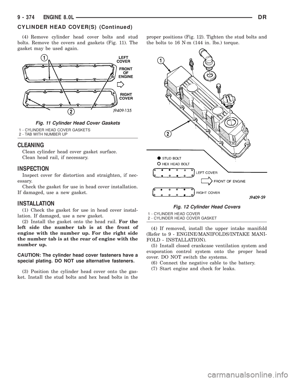
(4) Remove cylinder head cover bolts and stud
bolts. Remove the covers and gaskets (Fig. 11). The
gasket may be used again.
CLEANING
Clean cylinder head cover gasket surface.
Clean head rail, if necessary.
INSPECTION
Inspect cover for distortion and straighten, if nec-
essary.
Check the gasket for use in head cover installation.
If damaged, use a new gasket.
INSTALLATION
(1) Check the gasket for use in head cover instal-
lation. If damaged, use a new gasket.
(2) Install the gasket onto the head rail.For the
left side the number tab is at the front of
engine with the number up. For the right side
the number tab is at the rear of engine with the
number up.
CAUTION: The cylinder head cover fasteners have a
special plating. DO NOT use alternative fasteners.
(3) Position the cylinder head cover onto the gas-
ket. Install the stud bolts and hex head bolts in theproper positions (Fig. 12). Tighten the stud bolts and
the bolts to 16 N´m (144 in. lbs.) torque.
(4) If removed, install the upper intake manifold
(Refer to 9 - ENGINE/MANIFOLDS/INTAKE MANI-
FOLD - INSTALLATION).
(5) Install closed crankcase ventilation system and
evaporation control system onto the proper head
cover. DO NOT switch the systems.
(6) Connect the negative cable to the battery.
(7) Start engine and check for leaks.
Fig. 11 Cylinder Head Cover Gaskets
1 - CYLINDER HEAD COVER GASKETS
2 - TAB WITH NUMBER UP
Fig. 12 Cylinder Head Covers
1 - CYLINDER HEAD COVER
2 - CYLINDER HEAD COVER GASKET
9 - 374 ENGINE 8.0LDR
CYLINDER HEAD COVER(S) (Continued)
Page 1629 of 2895
(1) Install the push rods in the same order as
removed.
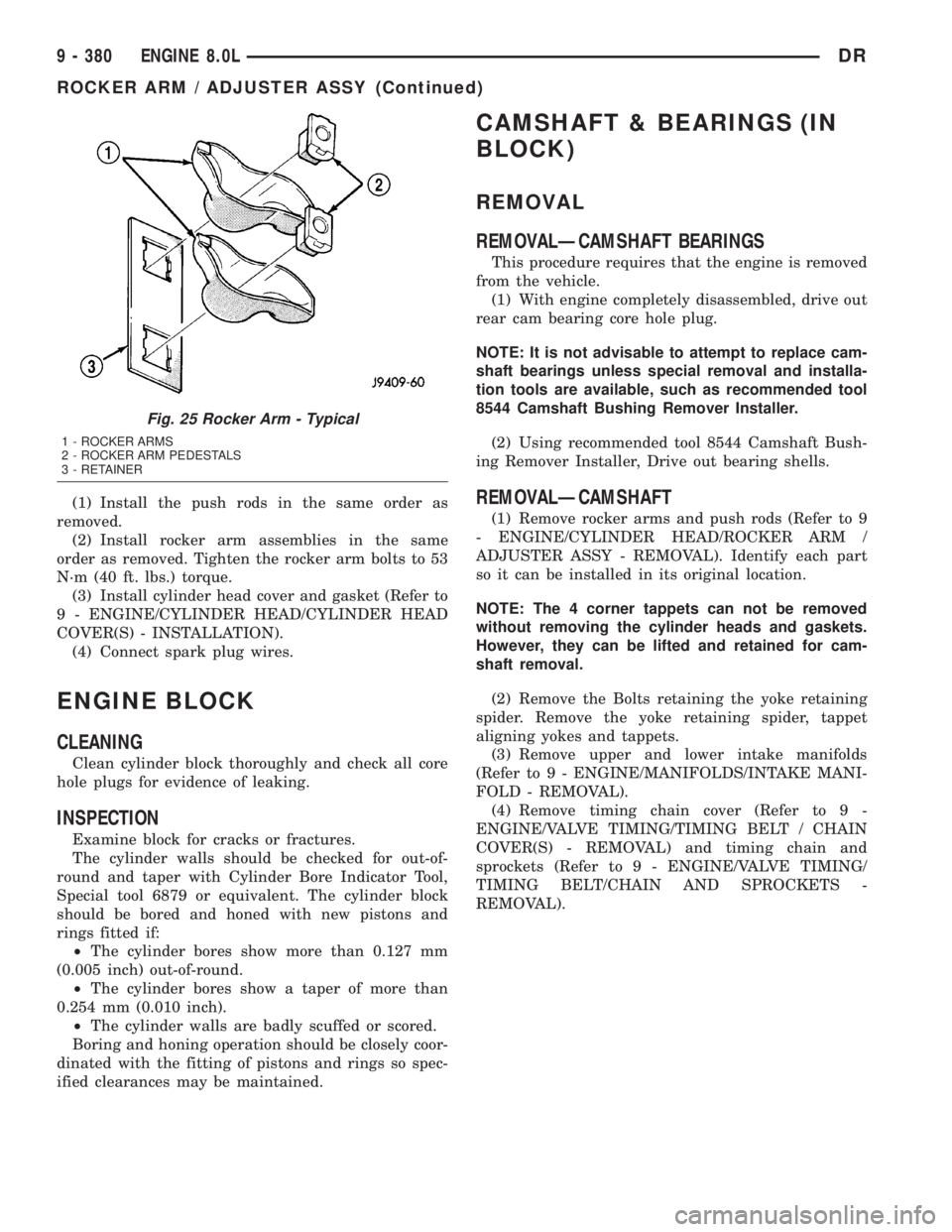
(2) Install rocker arm assemblies in the same
order as removed. Tighten the rocker arm bolts to 53
N´m (40 ft. lbs.) torque.
(3) Install cylinder head cover and gasket (Refer to
9 - ENGINE/CYLINDER HEAD/CYLINDER HEAD
COVER(S) - INSTALLATION).
(4) Connect spark plug wires.
ENGINE BLOCK
CLEANING
Clean cylinder block thoroughly and check all core
hole plugs for evidence of leaking.
INSPECTION
Examine block for cracks or fractures.
The cylinder walls should be checked for out-of-
round and taper with Cylinder Bore Indicator Tool,
Special tool 6879 or equivalent. The cylinder block
should be bored and honed with new pistons and
rings fitted if:
²The cylinder bores show more than 0.127 mm
(0.005 inch) out-of-round.
²The cylinder bores show a taper of more than
0.254 mm (0.010 inch).
²The cylinder walls are badly scuffed or scored.
Boring and honing operation should be closely coor-
dinated with the fitting of pistons and rings so spec-
ified clearances may be maintained.
CAMSHAFT & BEARINGS (IN
BLOCK)
REMOVAL
REMOVALÐCAMSHAFT BEARINGS
This procedure requires that the engine is removed
from the vehicle.
(1) With engine completely disassembled, drive out
rear cam bearing core hole plug.
NOTE: It is not advisable to attempt to replace cam-
shaft bearings unless special removal and installa-
tion tools are available, such as recommended tool
8544 Camshaft Bushing Remover Installer.
(2) Using recommended tool 8544 Camshaft Bush-
ing Remover Installer, Drive out bearing shells.
REMOVALÐCAMSHAFT
(1) Remove rocker arms and push rods (Refer to 9
- ENGINE/CYLINDER HEAD/ROCKER ARM /
ADJUSTER ASSY - REMOVAL). Identify each part
so it can be installed in its original location.
NOTE: The 4 corner tappets can not be removed
without removing the cylinder heads and gaskets.
However, they can be lifted and retained for cam-
shaft removal.
(2) Remove the Bolts retaining the yoke retaining
spider. Remove the yoke retaining spider, tappet
aligning yokes and tappets.
(3) Remove upper and lower intake manifolds
(Refer to 9 - ENGINE/MANIFOLDS/INTAKE MANI-
FOLD - REMOVAL).
(4) Remove timing chain cover (Refer to 9 -
ENGINE/VALVE TIMING/TIMING BELT / CHAIN
COVER(S) - REMOVAL) and timing chain and
sprockets (Refer to 9 - ENGINE/VALVE TIMING/
TIMING BELT/CHAIN AND SPROCKETS -
REMOVAL).
Fig. 25 Rocker Arm - Typical
1 - ROCKER ARMS
2 - ROCKER ARM PEDESTALS
3 - RETAINER
9 - 380 ENGINE 8.0LDR
ROCKER ARM / ADJUSTER ASSY (Continued)
Page 1631 of 2895
(13) Install the rocker arms (Refer to 9 - ENGINE/
CYLINDER HEAD/ROCKER ARM / ADJUSTER
ASSY - INSTALLATION).
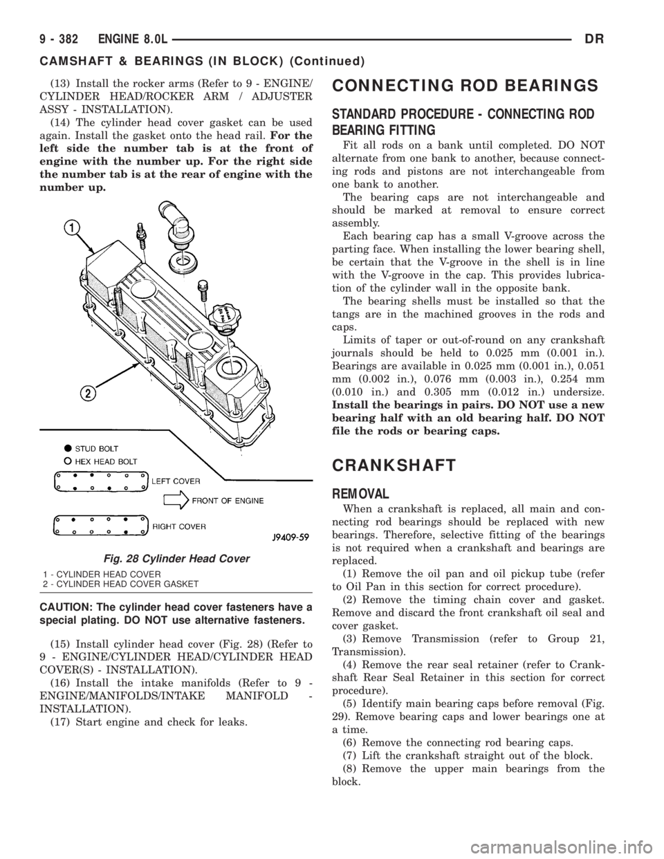
(14) The cylinder head cover gasket can be used
again. Install the gasket onto the head rail.For the
left side the number tab is at the front of
engine with the number up. For the right side
the number tab is at the rear of engine with the
number up.
CAUTION: The cylinder head cover fasteners have a
special plating. DO NOT use alternative fasteners.
(15) Install cylinder head cover (Fig. 28) (Refer to
9 - ENGINE/CYLINDER HEAD/CYLINDER HEAD
COVER(S) - INSTALLATION).
(16) Install the intake manifolds (Refer to 9 -
ENGINE/MANIFOLDS/INTAKE MANIFOLD -
INSTALLATION).
(17) Start engine and check for leaks.CONNECTING ROD BEARINGS
STANDARD PROCEDURE - CONNECTING ROD
BEARING FITTING
Fit all rods on a bank until completed. DO NOT
alternate from one bank to another, because connect-
ing rods and pistons are not interchangeable from
one bank to another.
The bearing caps are not interchangeable and
should be marked at removal to ensure correct
assembly.
Each bearing cap has a small V-groove across the
parting face. When installing the lower bearing shell,
be certain that the V-groove in the shell is in line
with the V-groove in the cap. This provides lubrica-
tion of the cylinder wall in the opposite bank.
The bearing shells must be installed so that the
tangs are in the machined grooves in the rods and
caps.
Limits of taper or out-of-round on any crankshaft
journals should be held to 0.025 mm (0.001 in.).
Bearings are available in 0.025 mm (0.001 in.), 0.051
mm (0.002 in.), 0.076 mm (0.003 in.), 0.254 mm
(0.010 in.) and 0.305 mm (0.012 in.) undersize.
Install the bearings in pairs. DO NOT use a new
bearing half with an old bearing half. DO NOT
file the rods or bearing caps.
CRANKSHAFT
REMOVAL
When a crankshaft is replaced, all main and con-
necting rod bearings should be replaced with new
bearings. Therefore, selective fitting of the bearings
is not required when a crankshaft and bearings are
replaced.
(1) Remove the oil pan and oil pickup tube (refer
to Oil Pan in this section for correct procedure).
(2) Remove the timing chain cover and gasket.
Remove and discard the front crankshaft oil seal and
cover gasket.
(3) Remove Transmission (refer to Group 21,
Transmission).
(4) Remove the rear seal retainer (refer to Crank-
shaft Rear Seal Retainer in this section for correct
procedure).
(5) Identify main bearing caps before removal (Fig.
29). Remove bearing caps and lower bearings one at
a time.
(6) Remove the connecting rod bearing caps.
(7) Lift the crankshaft straight out of the block.
(8) Remove the upper main bearings from the
block.
Fig. 28 Cylinder Head Cover
1 - CYLINDER HEAD COVER
2 - CYLINDER HEAD COVER GASKET
9 - 382 ENGINE 8.0LDR
CAMSHAFT & BEARINGS (IN BLOCK) (Continued)
Page 1636 of 2895
(4) The valve train generates a noise very much
like a light tappet noise during normal operation.
Care must be taken to ensure that tappets are mak-
ing the noise. If more than one tappet seems to be
noisy, it's probably not the tappets.
LEAK-DOWN TEST
After cleaning and inspection, test each tappet for
specified leak-down rate tolerance to ensure zero-lash
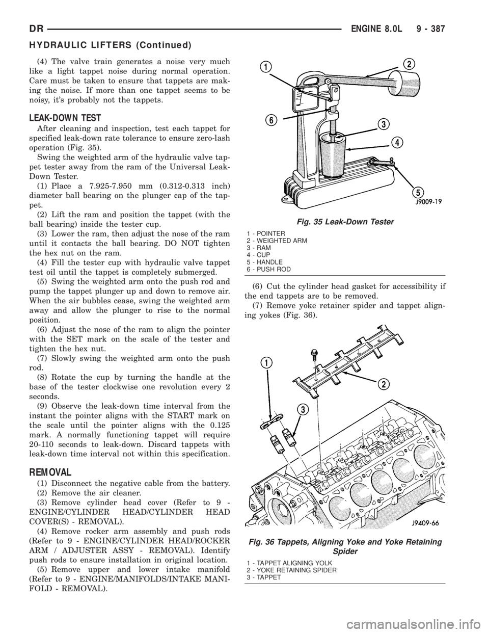
operation (Fig. 35).
Swing the weighted arm of the hydraulic valve tap-
pet tester away from the ram of the Universal Leak-
Down Tester.
(1) Place a 7.925-7.950 mm (0.312-0.313 inch)
diameter ball bearing on the plunger cap of the tap-
pet.
(2) Lift the ram and position the tappet (with the
ball bearing) inside the tester cup.
(3) Lower the ram, then adjust the nose of the ram
until it contacts the ball bearing. DO NOT tighten
the hex nut on the ram.
(4) Fill the tester cup with hydraulic valve tappet
test oil until the tappet is completely submerged.
(5) Swing the weighted arm onto the push rod and
pump the tappet plunger up and down to remove air.
When the air bubbles cease, swing the weighted arm
away and allow the plunger to rise to the normal
position.
(6) Adjust the nose of the ram to align the pointer
with the SET mark on the scale of the tester and
tighten the hex nut.
(7) Slowly swing the weighted arm onto the push
rod.
(8) Rotate the cup by turning the handle at the
base of the tester clockwise one revolution every 2
seconds.
(9) Observe the leak-down time interval from the
instant the pointer aligns with the START mark on
the scale until the pointer aligns with the 0.125
mark. A normally functioning tappet will require
20-110 seconds to leak-down. Discard tappets with
leak-down time interval not within this specification.
REMOVAL
(1) Disconnect the negative cable from the battery.
(2) Remove the air cleaner.
(3) Remove cylinder head cover (Refer to 9 -
ENGINE/CYLINDER HEAD/CYLINDER HEAD
COVER(S) - REMOVAL).
(4) Remove rocker arm assembly and push rods
(Refer to 9 - ENGINE/CYLINDER HEAD/ROCKER
ARM / ADJUSTER ASSY - REMOVAL). Identify
push rods to ensure installation in original location.
(5) Remove upper and lower intake manifold
(Refer to 9 - ENGINE/MANIFOLDS/INTAKE MANI-
FOLD - REMOVAL).(6) Cut the cylinder head gasket for accessibility if
the end tappets are to be removed.
(7) Remove yoke retainer spider and tappet align-
ing yokes (Fig. 36).
Fig. 35 Leak-Down Tester
1 - POINTER
2 - WEIGHTED ARM
3 - RAM
4 - CUP
5 - HANDLE
6 - PUSH ROD
Fig. 36 Tappets, Aligning Yoke and Yoke Retaining
Spider
1 - TAPPET ALIGNING YOLK
2 - YOKE RETAINING SPIDER
3 - TAPPET
DRENGINE 8.0L 9 - 387
HYDRAULIC LIFTERS (Continued)
Page 1637 of 2895
(8) Pull tappet out of bore with a twisting motion.
If all tappets are to be removed, identify tappets to
ensure installation in original location.
(9) If the tappet or bore in cylinder block is scored,
scuffed, or shows signs of sticking, ream the bore to
next oversize. Replace with oversize tappet.
(10) Check camshaft lobes for abnormal wear.
CLEANING
Clean tappet with a suitable solvent. Rinse in hot
water and blow dry with a clean shop rag or com-
pressed air.
INSTALLATION
(1) Lubricate tappets.
(2) Install tappets in their original positions.
Ensure that the oil bleed hole (if so equipped)
faces forward.
(3) Install tappet aligning yokes. Position the yoke
retainer spider over the tappet aligning yokes (Fig.
36)Install the yoke retaining spider bolts and tighten
to 22 N´m (16 ft. lbs.) torque.
(4) Install the push rods in their original location.
(5) Install the rocker arms (Refer to 9 - ENGINE/
CYLINDER HEAD/ROCKER ARM / ADJUSTER
ASSY - INSTALLATION).
(6) Install lower and upper intake manifold (Refer
to 9 - ENGINE/MANIFOLDS/INTAKE MANIFOLD -
INSTALLATION).
(7) The cylinder head cover gasket can be used
again. Install the gasket onto the head rail.For the
left side the number tab is at the front of
engine with the number up. For the right side
the number tab is at the rear of engine with the
number up.
(8) Install cylinder head cover (Refer to 9 -
ENGINE/CYLINDER HEAD/CYLINDER HEAD
COVER(S) - INSTALLATION).
(9) Install the air cleaner.
CAUTION: To prevent damage to valve mechanism,
engine must not be run above fast idle until all
hydraulic tappets have filled with oil and have
become quiet.
(10) Connect the negative cable to the battery.
(11) Road test vehicle and check for leaks.
PISTON & CONNECTING ROD
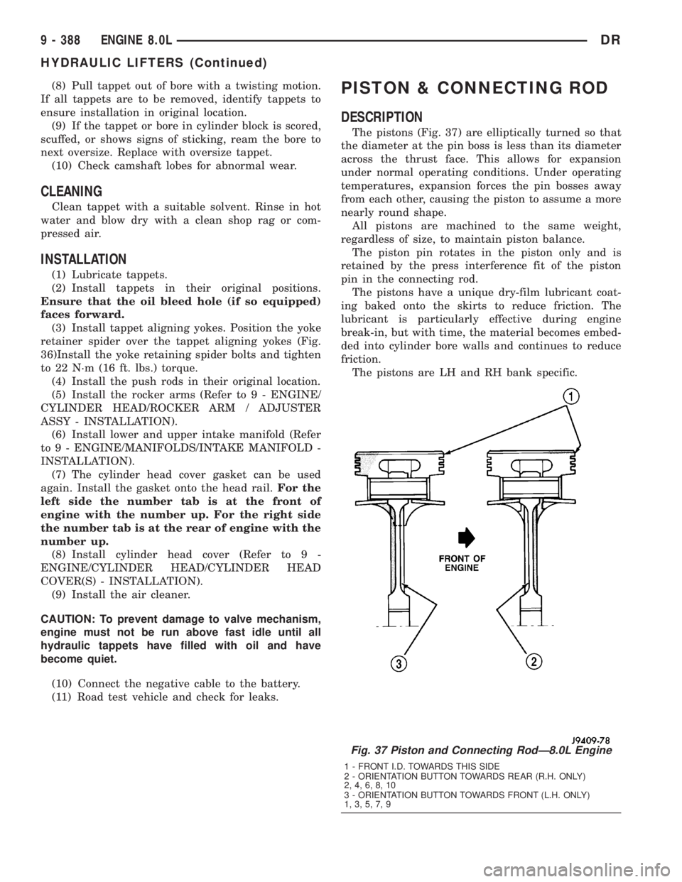
DESCRIPTION
The pistons (Fig. 37) are elliptically turned so that
the diameter at the pin boss is less than its diameter
across the thrust face. This allows for expansion
under normal operating conditions. Under operating
temperatures, expansion forces the pin bosses away
from each other, causing the piston to assume a more
nearly round shape.
All pistons are machined to the same weight,
regardless of size, to maintain piston balance.
The piston pin rotates in the piston only and is
retained by the press interference fit of the piston
pin in the connecting rod.
The pistons have a unique dry-film lubricant coat-
ing baked onto the skirts to reduce friction. The
lubricant is particularly effective during engine
break-in, but with time, the material becomes embed-
ded into cylinder bore walls and continues to reduce
friction.
The pistons are LH and RH bank specific.
Fig. 37 Piston and Connecting RodÐ8.0L Engine
1 - FRONT I.D. TOWARDS THIS SIDE
2 - ORIENTATION BUTTON TOWARDS REAR (R.H. ONLY)
2, 4, 6, 8, 10
3 - ORIENTATION BUTTON TOWARDS FRONT (L.H. ONLY)
1, 3, 5, 7, 9
9 - 388 ENGINE 8.0LDR
HYDRAULIC LIFTERS (Continued)
Page 1639 of 2895
NOTE: Be sure position of rings does not change
during the following step.
(5) Immerse the piston head and rings in clean
engine oil. Slide Piston Ring Compressor Tool C-385
over the piston and tighten with the special wrench
(part of Tool C-385).
(6) Install connecting rod bolt protectors on rod
bolts, a long protector should be installed on the
numbered side of the connecting rod.
(7) Rotate crankshaft so that the connecting rod
journal is on the center of the cylinder bore in the
bottom dead center (BDC) position. Be sure connect-
ing rod and cylinder bore number are the same.
Insert rod and piston into cylinder bore. Be sure the
piston and rod assemblies are installed in the proper
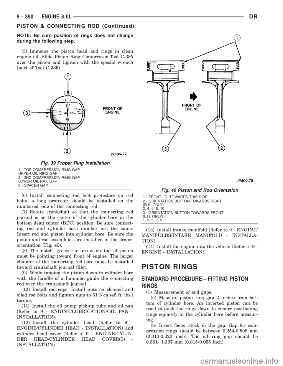
orientation (Fig. 40).
(8) The notch, groove or arrow on top of piston
must be pointing toward front of engine. The larger
chamfer of the connecting rod bore must be installed
toward crankshaft journal fillet.
(9) While tapping the piston down in cylinder bore
with the handle of a hammer, guide the connecting
rod over the crankshaft journal.
(10) Install rod caps. Install nuts on cleaned and
oiled rod bolts and tighten nuts to 61 N´m (45 ft. lbs.)
torque.
(11) Install the oil pump pick-up tube and oil pan
(Refer to 9 - ENGINE/LUBRICATION/OIL PAN -
INSTALLATION).
(12) Install the cylinder head (Refer to 9 -
ENGINE/CYLINDER HEAD - INSTALLATION) and
cylinder head cover (Refer to 9 - ENGINE/CYLIN-
DER HEAD/CYLINDER HEAD COVER(S) -
INSTALLATION).(13) Install intake manifold (Refer to 9 - ENGINE/
MANIFOLDS/INTAKE MANIFOLD - INSTALLA-
TION).
(14) Install the engine into the vehicle (Refer to 9 -
ENGINE - INSTALLATION).
PISTON RINGS
STANDARD PROCEDUREÐFITTING PISTON
RINGS
(1) Measurement of end gaps:
(a) Measure piston ring gap 2 inches from bot-
tom of cylinder bore. An inverted piston can be
used to push the rings down to ensure positioning
rings squarely in the cylinder bore before measur-
ing.
(b) Insert feeler stock in the gap. Gap for com-
pression rings should be between 0.254-0.508 mm
(0.010-0.020 inch). The oil ring gap should be
0.381- 1.397 mm (0.015-0.055 inch).
Fig. 39 Proper Ring Installation
1 - TOP COMPRESSION RING GAP
UPPER OIL RING GAP
2 - 2ND COMPRESSION RING GAP
LOWER OIL RAIL GAP
3 - SPACER GAP
Fig. 40 Piston and Rod Orientation
1 - FRONT I.D. TOWARDS THIS SIDE
2 - ORIENTATION BUTTON TOWARDS REAR
(R.H. ONLY)
2, 4, 6, 8, 10
3 - ORIENTATION BUTTON TOWARDS FRONT
(L.H. ONLY)
1, 3, 5, 7, 9
9 - 390 ENGINE 8.0LDR
PISTON & CONNECTING ROD (Continued)
Page 1641 of 2895
VIBRATION DAMPER
REMOVAL
(1) Disconnect the negative cable from the battery.
(2) Remove the following:
²Radiator fan (Refer to 7 - COOLING/ENGINE/
RADIATOR FAN - REMOVAL)
²Accessory drive belt (Refer to 7 - COOLING/AC-
CESSORY DRIVE/DRIVE BELTS - REMOVAL)
²Radiator (Refer to 7 - COOLING/ENGINE/RA-
DIATOR - REMOVAL)
(3) Remove crankshaft pulley/damper bolt and
washer from end of crankshaft.
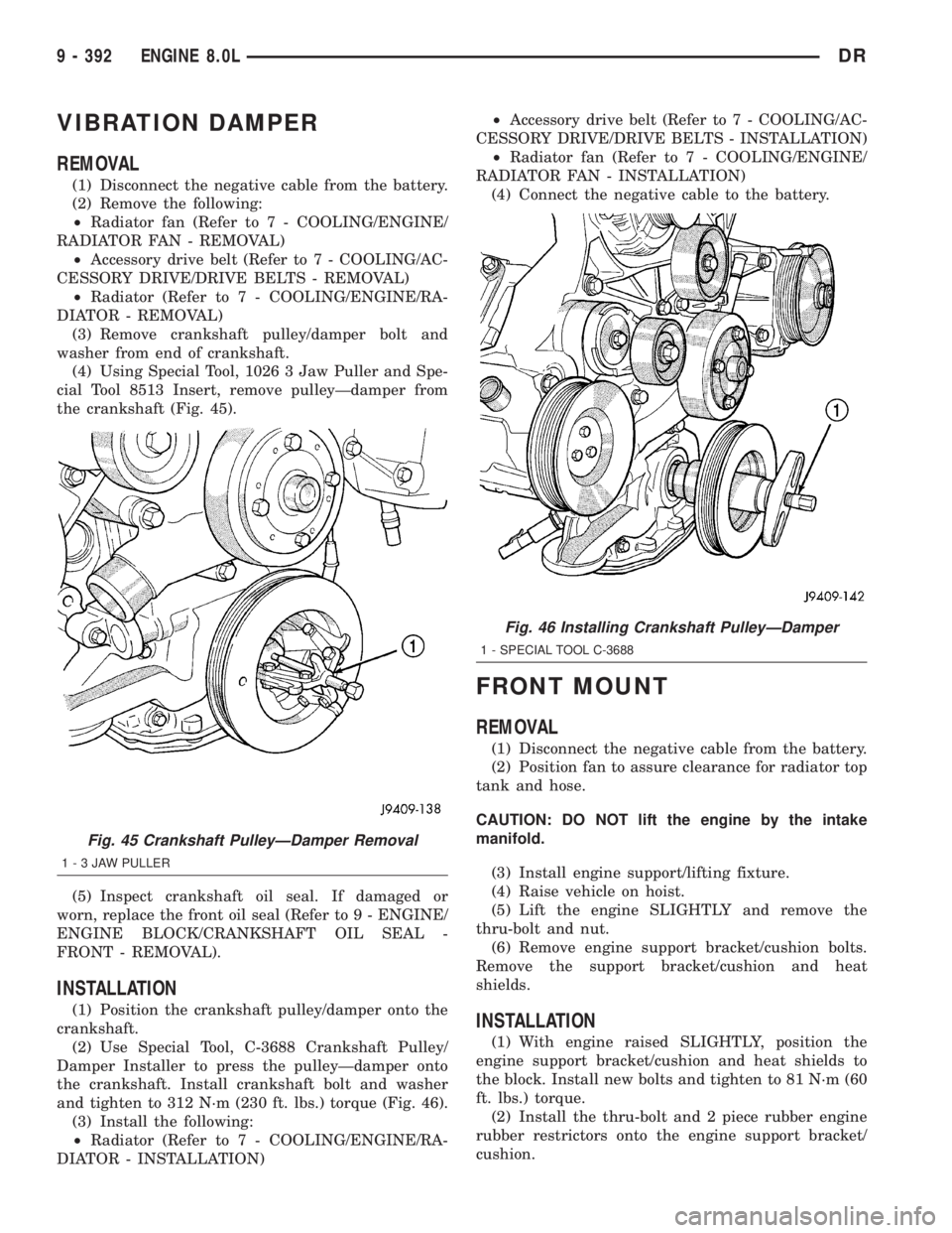
(4) Using Special Tool, 1026 3 Jaw Puller and Spe-
cial Tool 8513 Insert, remove pulleyÐdamper from
the crankshaft (Fig. 45).
(5) Inspect crankshaft oil seal. If damaged or
worn, replace the front oil seal (Refer to 9 - ENGINE/
ENGINE BLOCK/CRANKSHAFT OIL SEAL -
FRONT - REMOVAL).
INSTALLATION
(1) Position the crankshaft pulley/damper onto the
crankshaft.
(2) Use Special Tool, C-3688 Crankshaft Pulley/
Damper Installer to press the pulleyÐdamper onto
the crankshaft. Install crankshaft bolt and washer
and tighten to 312 N´m (230 ft. lbs.) torque (Fig. 46).
(3) Install the following:
²Radiator (Refer to 7 - COOLING/ENGINE/RA-
DIATOR - INSTALLATION)²Accessory drive belt (Refer to 7 - COOLING/AC-
CESSORY DRIVE/DRIVE BELTS - INSTALLATION)
²Radiator fan (Refer to 7 - COOLING/ENGINE/
RADIATOR FAN - INSTALLATION)
(4) Connect the negative cable to the battery.
FRONT MOUNT
REMOVAL
(1) Disconnect the negative cable from the battery.
(2) Position fan to assure clearance for radiator top
tank and hose.
CAUTION: DO NOT lift the engine by the intake
manifold.
(3) Install engine support/lifting fixture.
(4) Raise vehicle on hoist.
(5) Lift the engine SLIGHTLY and remove the
thru-bolt and nut.
(6) Remove engine support bracket/cushion bolts.
Remove the support bracket/cushion and heat
shields.
INSTALLATION
(1) With engine raised SLIGHTLY, position the
engine support bracket/cushion and heat shields to
the block. Install new bolts and tighten to 81 N´m (60
ft. lbs.) torque.
(2) Install the thru-bolt and 2 piece rubber engine
rubber restrictors onto the engine support bracket/
cushion.
Fig. 45 Crankshaft PulleyÐDamper Removal
1-3JAWPULLER
Fig. 46 Installing Crankshaft PulleyÐDamper
1 - SPECIAL TOOL C-3688
9 - 392 ENGINE 8.0LDR
Page 1650 of 2895
(7) Using a new pressure relief valve gasket,
install the relief valve plug. Tighten the plug to 20
N´m (15 ft. lbs.) torque.
(8) Install oil filter that has been filled with oil.
INTAKE MANIFOLD
DESCRIPTION
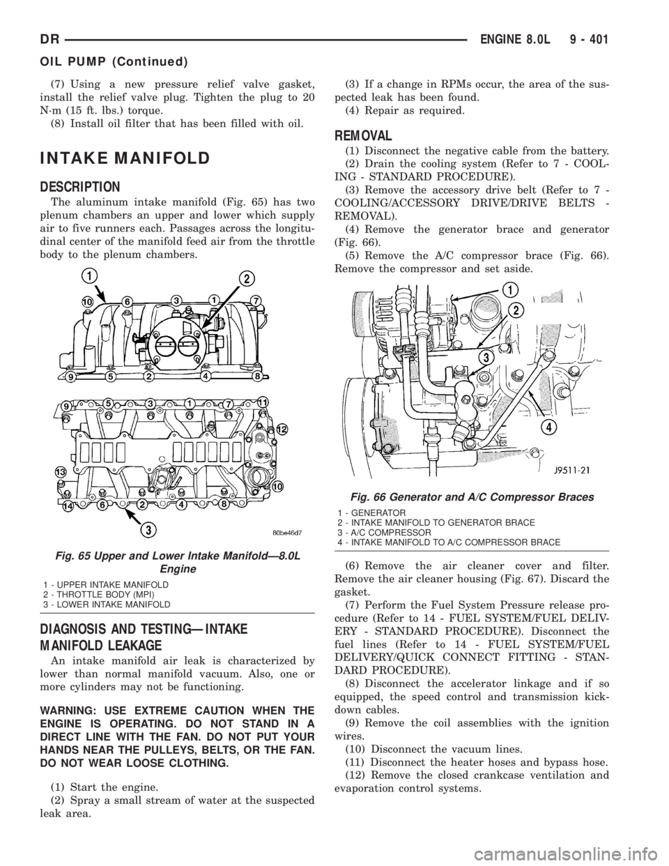
The aluminum intake manifold (Fig. 65) has two
plenum chambers an upper and lower which supply
air to five runners each. Passages across the longitu-
dinal center of the manifold feed air from the throttle
body to the plenum chambers.
DIAGNOSIS AND TESTINGÐINTAKE
MANIFOLD LEAKAGE
An intake manifold air leak is characterized by
lower than normal manifold vacuum. Also, one or
more cylinders may not be functioning.
WARNING: USE EXTREME CAUTION WHEN THE
ENGINE IS OPERATING. DO NOT STAND IN A
DIRECT LINE WITH THE FAN. DO NOT PUT YOUR
HANDS NEAR THE PULLEYS, BELTS, OR THE FAN.
DO NOT WEAR LOOSE CLOTHING.
(1) Start the engine.
(2) Spray a small stream of water at the suspected
leak area.(3) If a change in RPMs occur, the area of the sus-
pected leak has been found.
(4) Repair as required.
REMOVAL
(1) Disconnect the negative cable from the battery.
(2) Drain the cooling system (Refer to 7 - COOL-
ING - STANDARD PROCEDURE).
(3) Remove the accessory drive belt (Refer to 7 -
COOLING/ACCESSORY DRIVE/DRIVE BELTS -
REMOVAL).
(4) Remove the generator brace and generator
(Fig. 66).
(5) Remove the A/C compressor brace (Fig. 66).
Remove the compressor and set aside.
(6) Remove the air cleaner cover and filter.
Remove the air cleaner housing (Fig. 67). Discard the
gasket.
(7) Perform the Fuel System Pressure release pro-
cedure (Refer to 14 - FUEL SYSTEM/FUEL DELIV-
ERY - STANDARD PROCEDURE). Disconnect the
fuel lines (Refer to 14 - FUEL SYSTEM/FUEL
DELIVERY/QUICK CONNECT FITTING - STAN-
DARD PROCEDURE).
(8) Disconnect the accelerator linkage and if so
equipped, the speed control and transmission kick-
down cables.
(9) Remove the coil assemblies with the ignition
wires.
(10) Disconnect the vacuum lines.
(11) Disconnect the heater hoses and bypass hose.
(12) Remove the closed crankcase ventilation and
evaporation control systems.
Fig. 65 Upper and Lower Intake ManifoldÐ8.0L
Engine
1 - UPPER INTAKE MANIFOLD
2 - THROTTLE BODY (MPI)
3 - LOWER INTAKE MANIFOLD
Fig. 66 Generator and A/C Compressor Braces
1 - GENERATOR
2 - INTAKE MANIFOLD TO GENERATOR BRACE
3 - A/C COMPRESSOR
4 - INTAKE MANIFOLD TO A/C COMPRESSOR BRACE
DRENGINE 8.0L 9 - 401
OIL PUMP (Continued)
Page 1651 of 2895
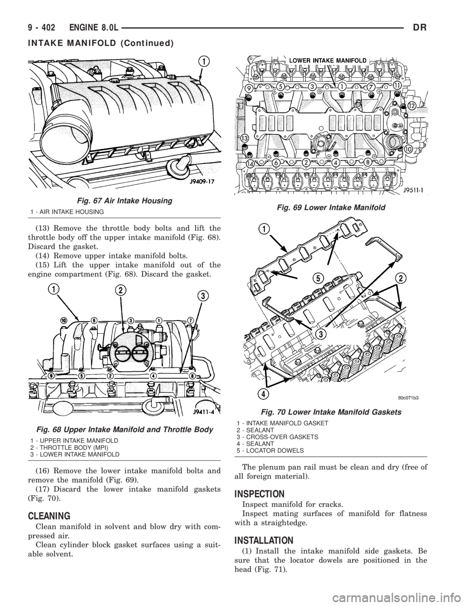
(13) Remove the throttle body bolts and lift the
throttle body off the upper intake manifold (Fig. 68).
Discard the gasket.
(14) Remove upper intake manifold bolts.
(15) Lift the upper intake manifold out of the
engine compartment (Fig. 68). Discard the gasket.
(16) Remove the lower intake manifold bolts and
remove the manifold (Fig. 69).
(17) Discard the lower intake manifold gaskets
(Fig. 70).
CLEANING
Clean manifold in solvent and blow dry with com-
pressed air.
Clean cylinder block gasket surfaces using a suit-
able solvent.The plenum pan rail must be clean and dry (free of
all foreign material).
INSPECTION
Inspect manifold for cracks.
Inspect mating surfaces of manifold for flatness
with a straightedge.
INSTALLATION
(1) Install the intake manifold side gaskets. Be
sure that the locator dowels are positioned in the
head (Fig. 71).
Fig. 67 Air Intake Housing
1 - AIR INTAKE HOUSING
Fig. 68 Upper Intake Manifold and Throttle Body
1 - UPPER INTAKE MANIFOLD
2 - THROTTLE BODY (MPI)
3 - LOWER INTAKE MANIFOLD
Fig. 69 Lower Intake Manifold
Fig. 70 Lower Intake Manifold Gaskets
1 - INTAKE MANIFOLD GASKET
2 - SEALANT
3 - CROSS-OVER GASKETS
4 - SEALANT
5 - LOCATOR DOWELS
9 - 402 ENGINE 8.0LDR
INTAKE MANIFOLD (Continued)
Page 1652 of 2895
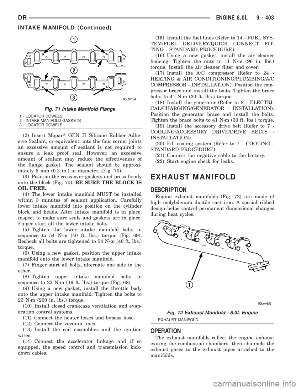
(2) Insert MopartGEN II Silicone Rubber Adhe-
sive Sealant, or equivalent, into the four corner joints
an excessive amount of sealant is not required to
ensure a leak proof seal. However, an excessive
amount of sealant may reduce the effectiveness of
the flange gasket. The sealant should be approxi-
mately 5 mm (0.2 in.) in diameter. (Fig. 70).
(3) Position the cross-over gaskets and press firmly
onto the block (Fig. 70).BE SURE THE BLOCK IS
OIL FREE..
(4) The lower intake manifold MUST be installed
within 3 minutes of sealant application. Carefully
lower intake manifold into position on the cylinder
block and heads. After intake manifold is in place,
inspect to make sure seals and gaskets are in place.
Finger start all the lower intake bolts.
(5) Tighten the lower intake manifold bolts in
sequence to 54 N´m (40 ft. lbs.) torque (Fig. 69).
Recheck all bolts are tightened to 54 N´m (40 ft. lbs.)
torque.
(6) Using a new gasket, position the upper intake
manifold onto the lower intake manifold.
(7) Finger start all bolts, alternate one side to the
other.
(8) Tighten upper intake manifold bolts in
sequence to 22 N´m (16 ft. lbs.) torque (Fig. 68).
(9) Using a new gasket, install the throttle body
onto the upper intake manifold. Tighten the bolts to
23 N´m (200 in. lbs.) torque.
(10) Install closed crankcase ventilation and evap-
oration control systems.
(11) Connect the heater hoses and bypass hose.
(12) Connect the vacuum lines.
(13) Install the coil assemblies and the ignition
wires.
(14) Connect the accelerator linkage and if so
equipped, the speed control and transmission kick-
down cables.(15) Install the fuel lines (Refer to 14 - FUEL SYS-
TEM/FUEL DELIVERY/QUICK CONNECT FIT-
TING - STANDARD PROCEDURE).
(16) Using a new gasket, install the air cleaner
housing. Tighten the nuts to 11 N´m (96 in. lbs.)
torque. Install the air cleaner filter and cover.
(17) Install the A/C compressor (Refer to 24 -
HEATING & AIR CONDITIONING/PLUMBING/A/C
COMPRESSOR - INSTALLATION). Position the com-
pressor brace and install the bolts. Tighten the brace
bolts to 41 N´m (30 ft. lbs.) torque.
(18) Install the generator (Refer to 8 - ELECTRI-
CAL/CHARGING/GENERATOR - INSTALLATION).
Position the generator brace and install the bolts.
Tighten the brace bolts to 41 N´m (30 ft. lbs.) torque.
(19) Install the accessory drive belt (Refer to 7 -
COOLING/ACCESSORY DRIVE/DRIVE BELTS -
INSTALLATION).
(20) Fill cooling system (Refer to 7 - COOLING -
STANDARD PROCEDURE).
(21) Connect the negative cable to the battery.
(22) Start engine check for leaks.
EXHAUST MANIFOLD
DESCRIPTION
Engine exhaust manifolds (Fig. 72) are made of
high molybdenum ductile cast iron. A special ribbed
design helps control permanent dimensional changes
during heat cycles.
OPERATION
The exhaust manifolds collect the engine exhaust
exiting the combustion chambers, then channels the
exhaust gases to the exhaust pipes attached to the
manifolds.
Fig. 71 Intake Manifold Flange
1 - LOCATOR DOWELS
2 - INTAKE MANIFOLD GASKETS
3 - LOCATOR DOWELS
Fig. 72 Exhaust ManifoldÐ8.0L Engine
1 - EXHAUST MANIFOLD
DRENGINE 8.0L 9 - 403
INTAKE MANIFOLD (Continued)