brake rotor DODGE RAM 2003 Service Repair Manual
[x] Cancel search | Manufacturer: DODGE, Model Year: 2003, Model line: RAM, Model: DODGE RAM 2003Pages: 2895, PDF Size: 83.15 MB
Page 28 of 2895
TOWING
STANDARD PROCEDURE - TOWING
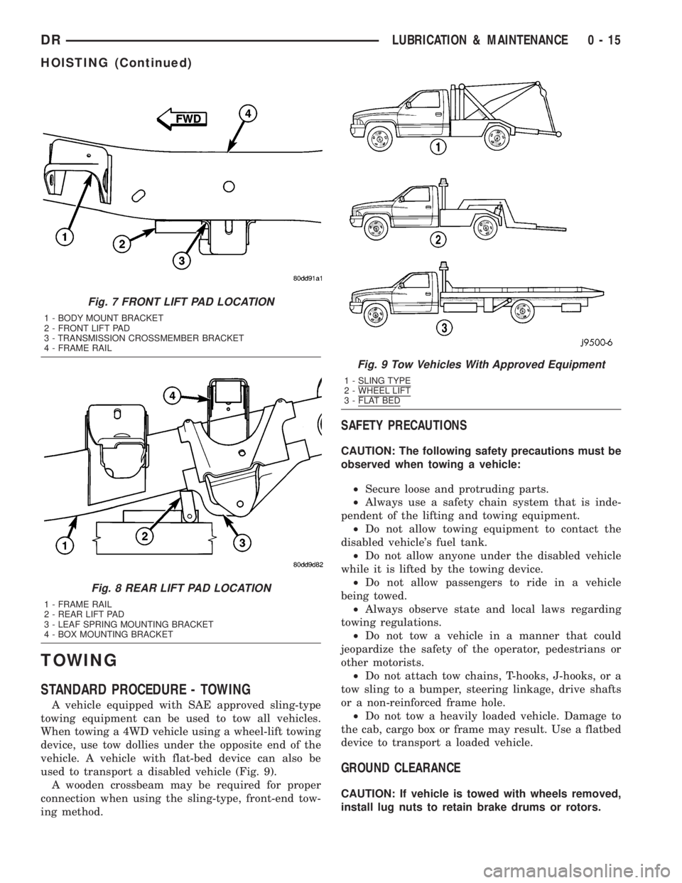
A vehicle equipped with SAE approved sling-type
towing equipment can be used to tow all vehicles.
When towing a 4WD vehicle using a wheel-lift towing
device, use tow dollies under the opposite end of the
vehicle. A vehicle with flat-bed device can also be
used to transport a disabled vehicle (Fig. 9).
A wooden crossbeam may be required for proper
connection when using the sling-type, front-end tow-
ing method.
SAFETY PRECAUTIONS
CAUTION: The following safety precautions must be
observed when towing a vehicle:
²Secure loose and protruding parts.
²Always use a safety chain system that is inde-
pendent of the lifting and towing equipment.
²Do not allow towing equipment to contact the
disabled vehicle's fuel tank.
²Do not allow anyone under the disabled vehicle
while it is lifted by the towing device.
²Do not allow passengers to ride in a vehicle
being towed.
²Always observe state and local laws regarding
towing regulations.
²Do not tow a vehicle in a manner that could
jeopardize the safety of the operator, pedestrians or
other motorists.
²Do not attach tow chains, T-hooks, J-hooks, or a
tow sling to a bumper, steering linkage, drive shafts
or a non-reinforced frame hole.
²Do not tow a heavily loaded vehicle. Damage to
the cab, cargo box or frame may result. Use a flatbed
device to transport a loaded vehicle.
GROUND CLEARANCE
CAUTION: If vehicle is towed with wheels removed,
install lug nuts to retain brake drums or rotors.
Fig. 7 FRONT LIFT PAD LOCATION
1 - BODY MOUNT BRACKET
2 - FRONT LIFT PAD
3 - TRANSMISSION CROSSMEMBER BRACKET
4 - FRAME RAIL
Fig. 8 REAR LIFT PAD LOCATION
1 - FRAME RAIL
2 - REAR LIFT PAD
3 - LEAF SPRING MOUNTING BRACKET
4 - BOX MOUNTING BRACKET
Fig. 9 Tow Vehicles With Approved Equipment
1 - SLING TYPE2 - WHEEL LIFT3 - FLAT BED
DRLUBRICATION & MAINTENANCE 0 - 15
HOISTING (Continued)
Page 29 of 2895
A towed vehicle should be raised until lifted wheels
are a minimum 100 mm (4 in) from the ground. Be
sure there is adequate ground clearance at the oppo-
site end of the vehicle, especially when towing over
rough terrain or steep rises in the road. If necessary,
remove the wheels from the lifted end of the vehicle
and lower the vehicle closer to the ground, to
increase the ground clearance at the opposite end of
the vehicle. Install lug nuts on wheel attaching studs
to retain brake drums or rotors.
RAMP ANGLE
If a vehicle with flat-bed towing equipment is used,
the approach ramp angle should not exceed 15
degrees.
TOWING WHEN KEYS ARE NOT AVAILABLE
When the vehicle is locked and keys are not avail-
able, use a flat bed hauler. A Wheel-lift or Sling-type
device can be used on 4WD vehicles providedall the
wheels are lifted off the ground using tow dol-
lies.
FOUR-WHEEL-DRIVE VEHICLE TOWING
Chrysler Corporation recommends that a vehicle be
transported on a flat-bed device. A Wheel-lift or
Sling-type device can be used providedall the
wheels are lifted off the ground using tow dol-
lies.
WARNING: WHEN TOWING A DISABLED VEHICLE
AND THE DRIVE WHEELS ARE SECURED IN A
WHEEL LIFT OR TOW DOLLIES, ENSURE THE
TRANSMISSION IS IN THE PARK POSITION (AUTO-
MATIC TRANSMISSION) OR A FORWARD DRIVE
GEAR (MANUAL TRANSMISSION).
CAUTION: Many vehicles are equipped with air
dams, spoilers, and/or ground effect panels. To
avoid component damage, a wheel-lift towing vehi-
cle or a flat-bed hauling vehicle is recommended.
0 - 16 LUBRICATION & MAINTENANCEDR
TOWING (Continued)
Page 44 of 2895
LARGE BUSHING
NOTE: Extreme pressure lubrication must be used
on the threaded portions of the tool. This will
increase the longevity of the tool and insure proper
operation during the removal and installation pro-
cess.
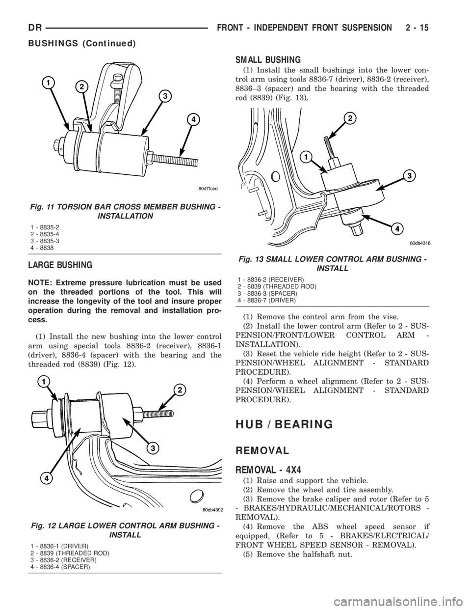
(1) Install the new bushing into the lower control
arm using special tools 8836-2 (receiver), 8836-1
(driver), 8836-4 (spacer) with the bearing and the
threaded rod (8839) (Fig. 12).
SMALL BUSHING
(1) Install the small bushings into the lower con-
trol arm using tools 8836-7 (driver), 8836-2 (receiver),
8836±3 (spacer) and the bearing with the threaded
rod (8839) (Fig. 13).
(1) Remove the control arm from the vise.
(2) Install the lower control arm (Refer to 2 - SUS-
PENSION/FRONT/LOWER CONTROL ARM -
INSTALLATION).
(3) Reset the vehicle ride height (Refer to 2 - SUS-
PENSION/WHEEL ALIGNMENT - STANDARD
PROCEDURE).
(4) Perform a wheel alignment (Refer to 2 - SUS-
PENSION/WHEEL ALIGNMENT - STANDARD
PROCEDURE).
HUB / BEARING
REMOVAL
REMOVAL - 4X4
(1) Raise and support the vehicle.
(2) Remove the wheel and tire assembly.
(3) Remove the brake caliper and rotor (Refer to 5
- BRAKES/HYDRAULIC/MECHANICAL/ROTORS -
REMOVAL).
(4) Remove the ABS wheel speed sensor if
equipped, (Refer to 5 - BRAKES/ELECTRICAL/
FRONT WHEEL SPEED SENSOR - REMOVAL).
(5) Remove the halfshaft nut.
Fig. 11 TORSION BAR CROSS MEMBER BUSHING -
INSTALLATION
1 - 8835-2
2 - 8835-4
3 - 8835-3
4 - 8838
Fig. 12 LARGE LOWER CONTROL ARM BUSHING -
INSTALL
1 - 8836-1 (DRIVER)
2 - 8839 (THREADED ROD)
3 - 8836-2 (RECEIVER)
4 - 8836-4 (SPACER)
Fig. 13 SMALL LOWER CONTROL ARM BUSHING -
INSTALL
1 - 8836-2 (RECEIVER)
2 - 8839 (THREADED ROD)
3 - 8836-3 (SPACER)
4 - 8836-7 (DRIVER)
DRFRONT - INDEPENDENT FRONT SUSPENSION 2 - 15
BUSHINGS (Continued)
Page 45 of 2895
NOTE: Do not strike the knuckle with a hammer to
remove the tie rod end or the ball joint. Damage to
the steering knuckle will occur.
(6) Remove the tie rod end nut and separate the
tie rod from the knuckle using special tool 8677.
(7) Remove the upper ball joint nut and separate
the upper ball joint from the knuckle using special
tool 8677.
(8) Pull down on the steering knuckle to separate
the halfshaft from the hub/bearing.
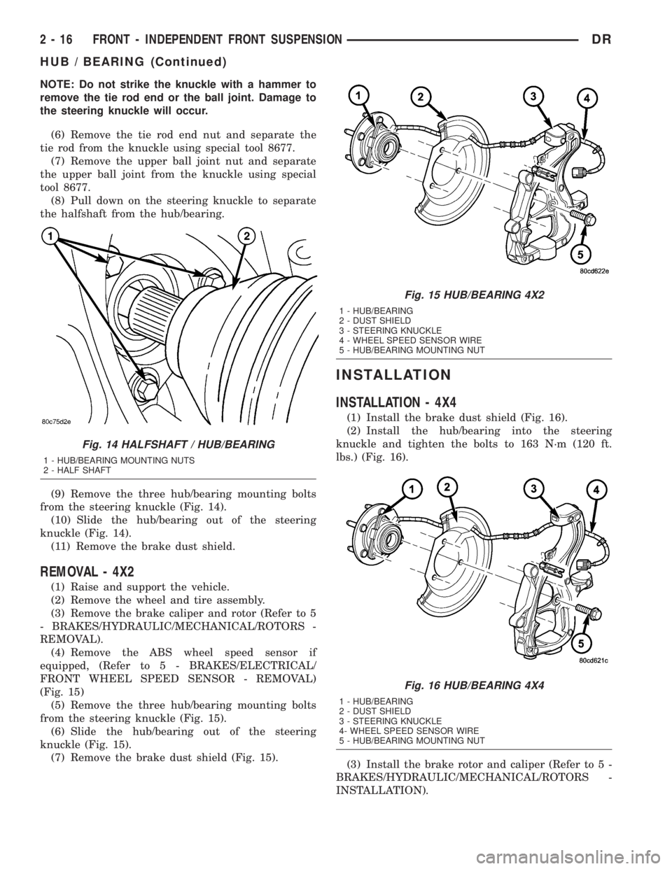
(9) Remove the three hub/bearing mounting bolts
from the steering knuckle (Fig. 14).
(10) Slide the hub/bearing out of the steering
knuckle (Fig. 14).
(11) Remove the brake dust shield.
REMOVAL - 4X2
(1) Raise and support the vehicle.
(2) Remove the wheel and tire assembly.
(3) Remove the brake caliper and rotor (Refer to 5
- BRAKES/HYDRAULIC/MECHANICAL/ROTORS -
REMOVAL).
(4) Remove the ABS wheel speed sensor if
equipped, (Refer to 5 - BRAKES/ELECTRICAL/
FRONT WHEEL SPEED SENSOR - REMOVAL)
(Fig. 15)
(5) Remove the three hub/bearing mounting bolts
from the steering knuckle (Fig. 15).
(6) Slide the hub/bearing out of the steering
knuckle (Fig. 15).
(7) Remove the brake dust shield (Fig. 15).
INSTALLATION
INSTALLATION - 4X4
(1) Install the brake dust shield (Fig. 16).
(2) Install the hub/bearing into the steering
knuckle and tighten the bolts to 163 N´m (120 ft.
lbs.) (Fig. 16).
(3) Install the brake rotor and caliper (Refer to 5 -
BRAKES/HYDRAULIC/MECHANICAL/ROTORS -
INSTALLATION).
Fig. 14 HALFSHAFT / HUB/BEARING
1 - HUB/BEARING MOUNTING NUTS
2 - HALF SHAFT
Fig. 15 HUB/BEARING 4X2
1 - HUB/BEARING
2 - DUST SHIELD
3 - STEERING KNUCKLE
4 - WHEEL SPEED SENSOR WIRE
5 - HUB/BEARING MOUNTING NUT
Fig. 16 HUB/BEARING 4X4
1 - HUB/BEARING
2 - DUST SHIELD
3 - STEERING KNUCKLE
4- WHEEL SPEED SENSOR WIRE
5 - HUB/BEARING MOUNTING NUT
2 - 16 FRONT - INDEPENDENT FRONT SUSPENSIONDR
HUB / BEARING (Continued)
Page 46 of 2895
(4) Install the ABS wheel speed sensor if equipped
(Refer to 5 - BRAKES/ELECTRICAL/FRONT
WHEEL SPEED SENSOR - INSTALLATION).
(5) Install the upper ball joint nut to the steering
knuckle and tighten to 54 N´m (40 ft. lbs.) (on 1500
series only an additional 90É turn).
(6) Install the tie rod end nut to the steering
knuckle and tighten to 61 N´m (45 ft. lbs.) then an
additional 90É.
(7) Install the halfshaft nut and tighten to 251
N´m (185 ft. lbs.).
(8) Install the wheel and tire assembly (Refer to 22
- TIRES/WHEELS/WHEELS - STANDARD PROCE-
DURE).
(9) Remove the support and lower vehicle.
INSTALLATION - 4X2
(1) Install the brake dust shield (Fig. 15).
(2) Install the hub/bearing into the steering
knuckle and tighten the bolts to 163 N´m (120 ft.
lbs.) (Fig. 15).
(3) Install the brake rotor and caliper (Refer to 5 -
BRAKES/HYDRAULIC/MECHANICAL/ROTORS -
INSTALLATION).
(4) Install the ABS wheel speed sensor if equipped
(Refer to 5 - BRAKES/ELECTRICAL/FRONT
WHEEL SPEED SENSOR - INSTALLATION) (Fig.
15).
(5) Install the wheel and tire assembly (Refer to 22
- TIRES/WHEELS/WHEELS - STANDARD PROCE-
DURE).
(6) Remove the support and lower vehicle.
KNUCKLE
DESCRIPTION
The knuckle is a single casting with legs machined
for the upper and lower ball joints. The knuckle also
has machined mounting locations for the front brake
calipers and hub bearing.
OPERATION
The steering knuckle pivot between the upper and
lower ball joint. Steering linkage attached to the
knuckle allows the vehicle to be steered.
REMOVAL
(1) Raise and support the vehicle.
(2) Remove the wheel and tire assembly.
(3) Remove the brake caliper, rotor (Refer to 5 -
BRAKES/HYDRAULIC/MECHANICAL/ROTORS -
REMOVAL), shield and ABS wheel speed sensor if
equipped (Refer to 5 - BRAKES/ELECTRICAL/
FRONT WHEEL SPEED SENSOR - REMOVAL).
(4) Remove the front halfshaft nut (if equipped).(5) Remove the tie rod end nut. Separate the tie
rod from the knuckle with Remover 8677.
CAUTION: When installing Remover 8677 to sepa-
rate the ball joint, be careful not to damage the ball
joint seal.
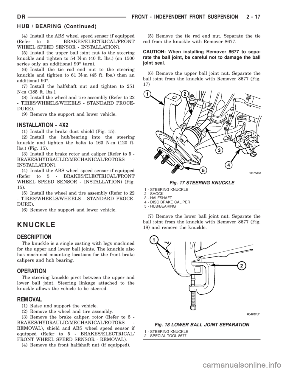
(6) Remove the upper ball joint nut. Separate the
ball joint from the knuckle with Remover 8677 (Fig.
17)
(7) Remove the lower ball joint nut. Separate the
ball joint from the knuckle with Remover 8677 (Fig.
18) and remove the knuckle.
Fig. 17 STEERING KNUCKLE
1 - STEERING KNUCKLE
2 - SHOCK
3 - HALFSHAFT
4 - DISC BRAKE CALIPER
5 - HUB/BEARING
Fig. 18 LOWER BALL JOINT SEPARATION
1 - STEERING KNUCKLE
2 - SPECIAL TOOL 8677
DRFRONT - INDEPENDENT FRONT SUSPENSION 2 - 17
HUB / BEARING (Continued)
Page 47 of 2895
(8) Remove the hub/bearing from the steering
knuckle (Refer to 2 - SUSPENSION/FRONT/HUB /
BEARING - REMOVAL).
INSTALLATION
CAUTION: The ball joint stud tapers must be
CLEAN and DRY before installing the knuckle.
Clean the stud tapers with mineral spirits to remove
dirt and grease.
NOTE: When installing hub/bearing with ABS
brakes, position the speed sensor opening towards
the front of the vehicle.
(1) Install the hub/bearing to the steering knuckle
and tighten the bolts to 163 N´m (120 ft. lbs.)(LD) or
176 N´m (130 ft. lbs.)(HD 4X2) (Fig. 19).
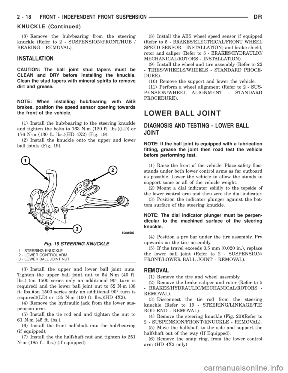
(2) Install the knuckle onto the upper and lower
ball joints (Fig. 19).
(3) Install the upper and lower ball joint nuts.
Tighten the upper ball joint nut to 54 N´m (40 ft.
lbs.) (on 1500 series only an additional 90É turn is
required) and the lower ball joint nut to 52 N´m (38
ft. lbs.)(on 1500 series only an additional 90É turn is
required)(LD) or 135 N´m (100 ft. lbs.)(HD 4X2).
(4) Remove the hydraulic jack from the lower sus-
pension arm.
(5) Install the tie rod end and tighten the nut to
61 N´m (45 ft. lbs.).
(6) Install the front halfshaft into the hub/bearing
(if equipped).
(7) Install the the halfshaft nut and tighten to 251
N´m (185 ft. lbs.) (if equipped).(8)
Install the ABS wheel speed sensor if equipped
(Refer to 5 - BRAKES/ELECTRICAL/FRONT WHEEL
SPEED SENSOR - INSTALLATION) and brake shield,
rotor and caliper (Refer to 5 - BRAKES/HYDRAULIC/
MECHANICAL/ROTORS - INSTALLATION).
(9) Install the wheel and tire assembly (Refer to 22
- TIRES/WHEELS/WHEELS - STANDARD PROCE-
DURE).
(10) Remove the support and lower the vehicle.
(11) Perform a wheel alignment (Refer to 2 - SUS-
PENSION/WHEEL ALIGNMENT - STANDARD
PROCEDURE).
LOWER BALL JOINT
DIAGNOSIS AND TESTING - LOWER BALL
JOINT
NOTE: If the ball joint is equipped with a lubrication
fitting, grease the joint then road test the vehicle
before performing test.
(1) Raise the front of the vehicle. Place safety floor
stands under both lower control arms as far outboard
as possible. Lower the vehicle to allow the stands to
support some or all of the vehicle weight.
(2)
Mount a dial indicator solidly to the topside of
the lower control arm and then zero the dial indicator.
(3) Position the indicator plunger against the bot-
tom surface of the steering knuckle.
NOTE: The dial indicator plunger must be perpen-
dicular to the machined surface of the steering
knuckle.
(4) Position a pry bar under the tire assembly. Pry
upwards on the tire assembly.
(5) If the travel exceeds 0.5 mm (0.020 in.), replace
the lower ball joint (Refer to 2 - SUSPENSION/
FRONT/LOWER BALL JOINT - REMOVAL).
REMOVAL
(1) Remove the tire and wheel assembly.
(2) Remove the brake caliper and rotor (Refer to 5
- BRAKES/HYDRAULIC/MECHANICAL/ROTORS -
REMOVAL).
(3) Disconnect the tie rod from the steering
knuckle (Refer to 19 - STEERING/LINKAGE/TIE
ROD END - REMOVAL).
(4) Remove the steering knuckle (Fig. 20)(Refer to
2 - SUSPENSION/FRONT/KNUCKLE - REMOVAL).
(5) Move the halfshaft to the side and support the
halfshaft out of the way (If Equipped).
(6) Remove the snap ring, from the lower control
arm (HD 4X2 only)
Fig. 19 STEERING KNUCKLE
1 - STEERING KNUCKLE
2 - LOWER CONTROL ARM
3 - LOWER BALL JOINT NUT
2 - 18 FRONT - INDEPENDENT FRONT SUSPENSIONDR
KNUCKLE (Continued)
Page 48 of 2895
NOTE: Extreme pressure lubrication must be used
on the threaded portions of the tool. This will
increase the longevity of the tool and insure proper
operation during the removal and installation pro-
cess.
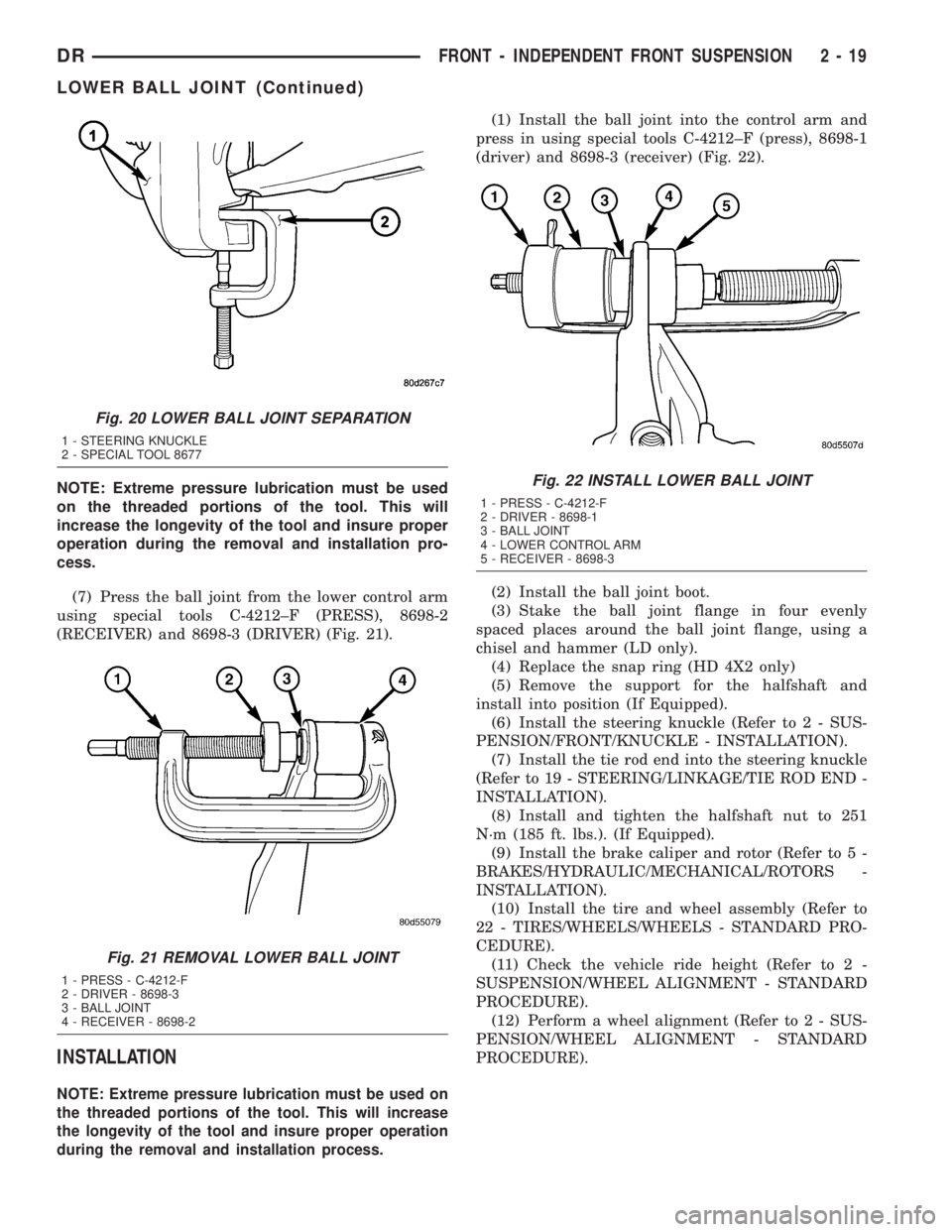
(7) Press the ball joint from the lower control arm
using special tools C-4212±F (PRESS), 8698-2
(RECEIVER) and 8698-3 (DRIVER) (Fig. 21).
INSTALLATION
NOTE: Extreme pressure lubrication must be used on
the threaded portions of the tool. This will increase
the longevity of the tool and insure proper operation
during the removal and installation process.
(1) Install the ball joint into the control arm and
press in using special tools C-4212±F (press), 8698-1
(driver) and 8698-3 (receiver) (Fig. 22).
(2) Install the ball joint boot.
(3) Stake the ball joint flange in four evenly
spaced places around the ball joint flange, using a
chisel and hammer (LD only).
(4) Replace the snap ring (HD 4X2 only)
(5) Remove the support for the halfshaft and
install into position (If Equipped).
(6) Install the steering knuckle (Refer to 2 - SUS-
PENSION/FRONT/KNUCKLE - INSTALLATION).
(7) Install the tie rod end into the steering knuckle
(Refer to 19 - STEERING/LINKAGE/TIE ROD END -
INSTALLATION).
(8) Install and tighten the halfshaft nut to 251
N´m (185 ft. lbs.). (If Equipped).
(9) Install the brake caliper and rotor (Refer to 5 -
BRAKES/HYDRAULIC/MECHANICAL/ROTORS -
INSTALLATION).
(10) Install the tire and wheel assembly (Refer to
22 - TIRES/WHEELS/WHEELS - STANDARD PRO-
CEDURE).
(11) Check the vehicle ride height (Refer to 2 -
SUSPENSION/WHEEL ALIGNMENT - STANDARD
PROCEDURE).
(12) Perform a wheel alignment (Refer to 2 - SUS-
PENSION/WHEEL ALIGNMENT - STANDARD
PROCEDURE).
Fig. 20 LOWER BALL JOINT SEPARATION
1 - STEERING KNUCKLE
2 - SPECIAL TOOL 8677
Fig. 21 REMOVAL LOWER BALL JOINT
1 - PRESS - C-4212-F
2 - DRIVER - 8698-3
3 - BALL JOINT
4 - RECEIVER - 8698-2
Fig. 22 INSTALL LOWER BALL JOINT
1 - PRESS - C-4212-F
2 - DRIVER - 8698-1
3 - BALL JOINT
4 - LOWER CONTROL ARM
5 - RECEIVER - 8698-3
DRFRONT - INDEPENDENT FRONT SUSPENSION 2 - 19
LOWER BALL JOINT (Continued)
Page 59 of 2895
HUB / BEARING
REMOVAL
(1) Raise and support the vehicle.
(2) Remove the wheel and tire assembly.
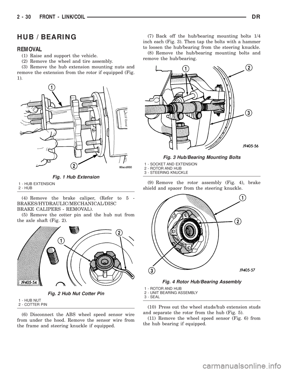
(3) Remove the hub extension mounting nuts and
remove the extension from the rotor if equipped (Fig.
1).
(4) Remove the brake caliper, (Refer to 5 -
BRAKES/HYDRAULIC/MECHANICAL/DISC
BRAKE CALIPERS - REMOVAL).
(5) Remove the cotter pin and the hub nut from
the axle shaft (Fig. 2).
(6) Disconnect the ABS wheel speed sensor wire
from under the hood. Remove the sensor wire from
the frame and steering knuckle if equipped.(7) Back off the hub/bearing mounting bolts 1/4
inch each (Fig. 3). Then tap the bolts with a hammer
to loosen the hub/bearing from the steering knuckle.
(8) Remove the hub/bearing mounting bolts and
remove the hub/bearing.
(9) Remove the rotor assembly (Fig. 4), brake
shield and spacer from the steering knuckle.
(10) Press out the wheel studs/hub extension studs
and separate the rotor from the hub (Fig. 5).
(11) Remove the wheel speed sensor (Fig. 6) from
the hub bearing if equipped.
Fig. 1 Hub Extension
1 - HUB EXTENSION
2 - HUB
Fig. 2 Hub Nut Cotter Pin
1 - HUB NUT
2 - COTTER PIN
Fig. 3 Hub/Bearing Mounting Bolts
1 - SOCKET AND EXTENSION
2 - ROTOR AND HUB
3 - STEERING KNUCKLE
Fig. 4 Rotor Hub/Bearing Assembly
1 - ROTOR AND HUB
2 - UNIT BEARING ASSEMBLY
3 - SEAL
2 - 30 FRONT - LINK/COILDR
Page 60 of 2895
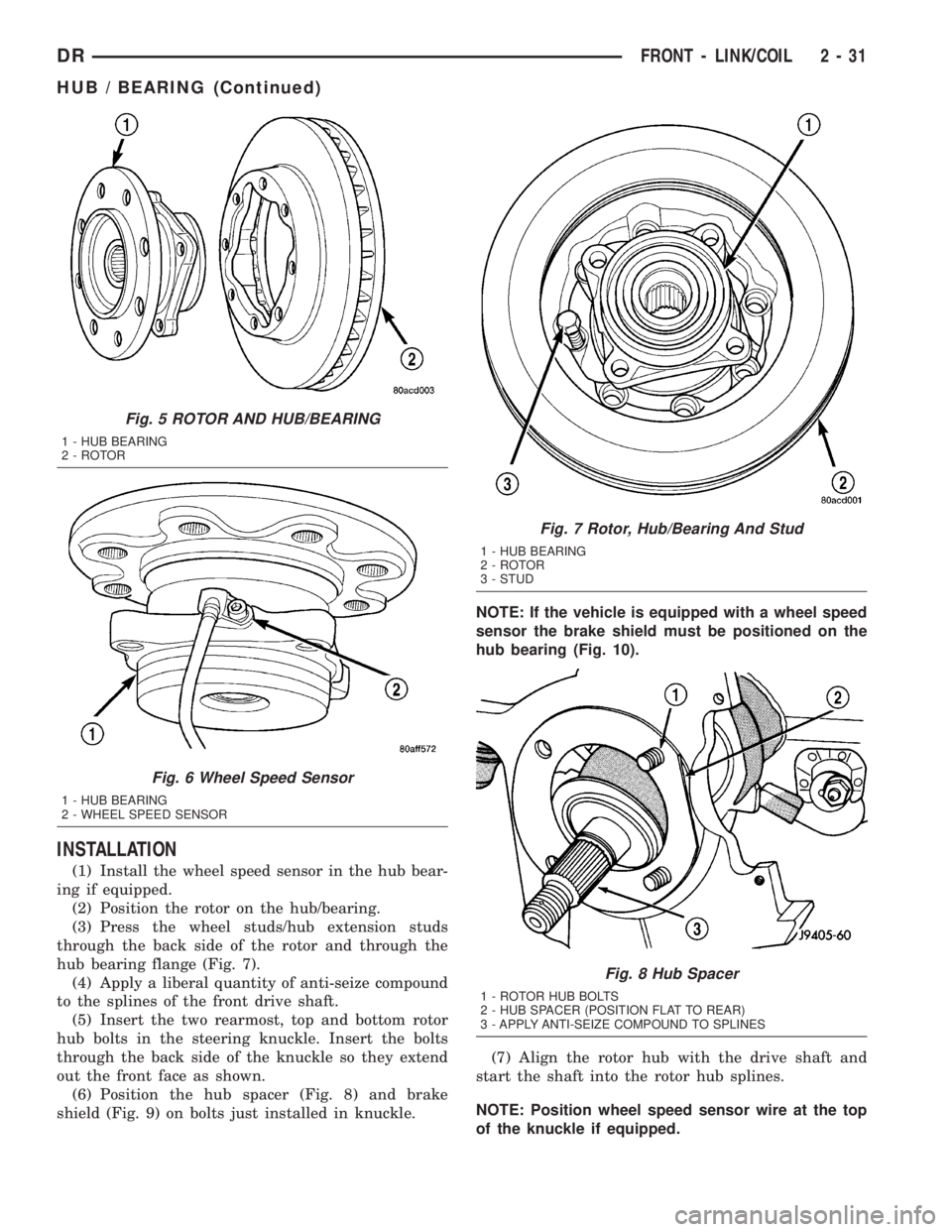
INSTALLATION
(1) Install the wheel speed sensor in the hub bear-
ing if equipped.
(2) Position the rotor on the hub/bearing.
(3) Press the wheel studs/hub extension studs
through the back side of the rotor and through the
hub bearing flange (Fig. 7).
(4) Apply a liberal quantity of anti-seize compound
to the splines of the front drive shaft.
(5) Insert the two rearmost, top and bottom rotor
hub bolts in the steering knuckle. Insert the bolts
through the back side of the knuckle so they extend
out the front face as shown.
(6) Position the hub spacer (Fig. 8) and brake
shield (Fig. 9) on bolts just installed in knuckle.NOTE: If the vehicle is equipped with a wheel speed
sensor the brake shield must be positioned on the
hub bearing (Fig. 10).
(7) Align the rotor hub with the drive shaft and
start the shaft into the rotor hub splines.
NOTE: Position wheel speed sensor wire at the top
of the knuckle if equipped.
Fig. 5 ROTOR AND HUB/BEARING
1 - HUB BEARING
2 - ROTOR
Fig. 6 Wheel Speed Sensor
1 - HUB BEARING
2 - WHEEL SPEED SENSOR
Fig. 7 Rotor, Hub/Bearing And Stud
1 - HUB BEARING
2 - ROTOR
3 - STUD
Fig. 8 Hub Spacer
1 - ROTOR HUB BOLTS
2 - HUB SPACER (POSITION FLAT TO REAR)
3 - APPLY ANTI-SEIZE COMPOUND TO SPLINES
DRFRONT - LINK/COIL 2 - 31
HUB / BEARING (Continued)
Page 75 of 2895
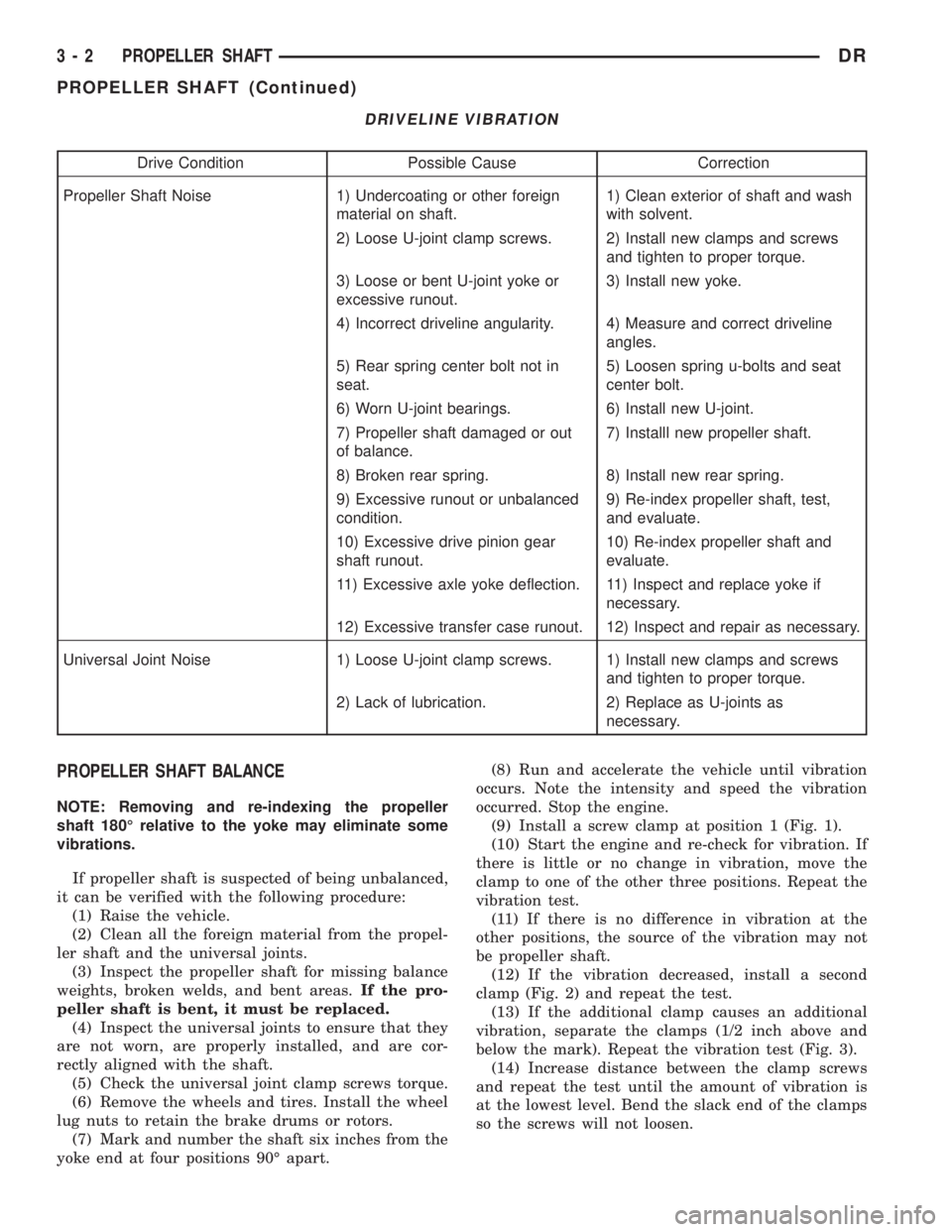
DRIVELINE VIBRATION
Drive Condition Possible Cause Correction
Propeller Shaft Noise 1) Undercoating or other foreign
material on shaft.1) Clean exterior of shaft and wash
with solvent.
2) Loose U-joint clamp screws. 2) Install new clamps and screws
and tighten to proper torque.
3) Loose or bent U-joint yoke or
excessive runout.3) Install new yoke.
4) Incorrect driveline angularity. 4) Measure and correct driveline
angles.
5) Rear spring center bolt not in
seat.5) Loosen spring u-bolts and seat
center bolt.
6) Worn U-joint bearings. 6) Install new U-joint.
7) Propeller shaft damaged or out
of balance.7) Installl new propeller shaft.
8) Broken rear spring. 8) Install new rear spring.
9) Excessive runout or unbalanced
condition.9) Re-index propeller shaft, test,
and evaluate.
10) Excessive drive pinion gear
shaft runout.10) Re-index propeller shaft and
evaluate.
11) Excessive axle yoke deflection. 11) Inspect and replace yoke if
necessary.
12) Excessive transfer case runout. 12) Inspect and repair as necessary.
Universal Joint Noise 1) Loose U-joint clamp screws. 1) Install new clamps and screws
and tighten to proper torque.
2) Lack of lubrication. 2) Replace as U-joints as
necessary.
PROPELLER SHAFT BALANCE
NOTE: Removing and re-indexing the propeller
shaft 180É relative to the yoke may eliminate some
vibrations.
If propeller shaft is suspected of being unbalanced,
it can be verified with the following procedure:
(1) Raise the vehicle.
(2) Clean all the foreign material from the propel-
ler shaft and the universal joints.
(3) Inspect the propeller shaft for missing balance
weights, broken welds, and bent areas.If the pro-
peller shaft is bent, it must be replaced.
(4) Inspect the universal joints to ensure that they
are not worn, are properly installed, and are cor-
rectly aligned with the shaft.
(5) Check the universal joint clamp screws torque.
(6) Remove the wheels and tires. Install the wheel
lug nuts to retain the brake drums or rotors.
(7) Mark and number the shaft six inches from the
yoke end at four positions 90É apart.(8) Run and accelerate the vehicle until vibration
occurs. Note the intensity and speed the vibration
occurred. Stop the engine.
(9) Install a screw clamp at position 1 (Fig. 1).
(10) Start the engine and re-check for vibration. If
there is little or no change in vibration, move the
clamp to one of the other three positions. Repeat the
vibration test.
(11) If there is no difference in vibration at the
other positions, the source of the vibration may not
be propeller shaft.
(12) If the vibration decreased, install a second
clamp (Fig. 2) and repeat the test.
(13) If the additional clamp causes an additional
vibration, separate the clamps (1/2 inch above and
below the mark). Repeat the vibration test (Fig. 3).
(14) Increase distance between the clamp screws
and repeat the test until the amount of vibration is
at the lowest level. Bend the slack end of the clamps
so the screws will not loosen.
3 - 2 PROPELLER SHAFTDR
PROPELLER SHAFT (Continued)