ignition coil DODGE RAM 2003 Service Repair Manual
[x] Cancel search | Manufacturer: DODGE, Model Year: 2003, Model line: RAM, Model: DODGE RAM 2003Pages: 2895, PDF Size: 83.15 MB
Page 310 of 2895
NOTE: A used belt should be replaced if tensioner
indexing arrow has moved to the minimum tension
indicator. Tensioner travel stops at this point.
(1) Remove accessory drive belt (Refer to 7 -
COOLING/ACCESSORY DRIVE/DRIVE BELTS -
REMOVAL).
(2) Remove tensioner assembly from mounting
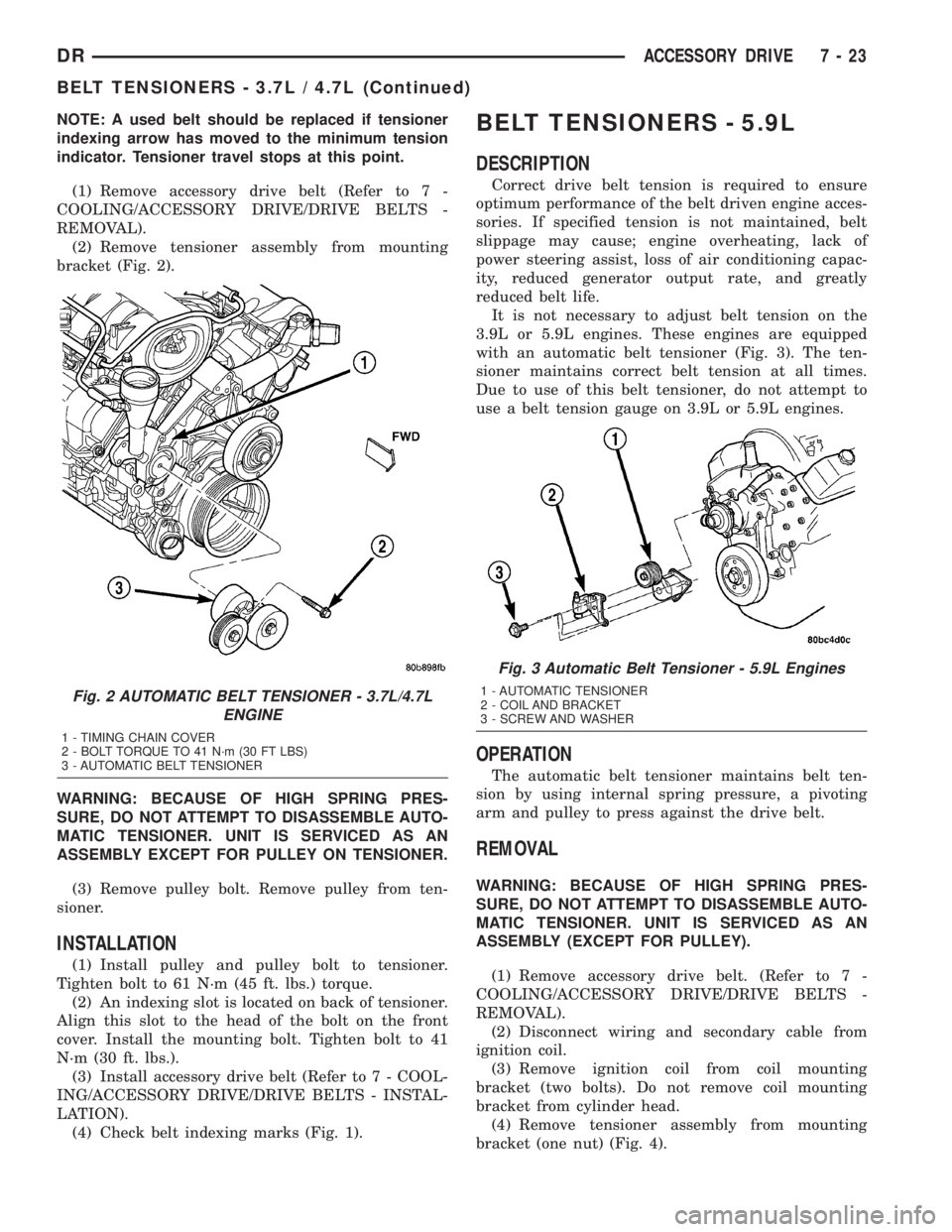
bracket (Fig. 2).
WARNING: BECAUSE OF HIGH SPRING PRES-
SURE, DO NOT ATTEMPT TO DISASSEMBLE AUTO-
MATIC TENSIONER. UNIT IS SERVICED AS AN
ASSEMBLY EXCEPT FOR PULLEY ON TENSIONER.
(3) Remove pulley bolt. Remove pulley from ten-
sioner.
INSTALLATION
(1) Install pulley and pulley bolt to tensioner.
Tighten bolt to 61 N´m (45 ft. lbs.) torque.
(2) An indexing slot is located on back of tensioner.
Align this slot to the head of the bolt on the front
cover. Install the mounting bolt. Tighten bolt to 41
N´m (30 ft. lbs.).
(3) Install accessory drive belt (Refer to 7 - COOL-
ING/ACCESSORY DRIVE/DRIVE BELTS - INSTAL-
LATION).
(4) Check belt indexing marks (Fig. 1).
BELT TENSIONERS - 5.9L
DESCRIPTION
Correct drive belt tension is required to ensure
optimum performance of the belt driven engine acces-
sories. If specified tension is not maintained, belt
slippage may cause; engine overheating, lack of
power steering assist, loss of air conditioning capac-
ity, reduced generator output rate, and greatly
reduced belt life.
It is not necessary to adjust belt tension on the
3.9L or 5.9L engines. These engines are equipped
with an automatic belt tensioner (Fig. 3). The ten-
sioner maintains correct belt tension at all times.
Due to use of this belt tensioner, do not attempt to
use a belt tension gauge on 3.9L or 5.9L engines.
OPERATION
The automatic belt tensioner maintains belt ten-
sion by using internal spring pressure, a pivoting
arm and pulley to press against the drive belt.
REMOVAL
WARNING: BECAUSE OF HIGH SPRING PRES-
SURE, DO NOT ATTEMPT TO DISASSEMBLE AUTO-
MATIC TENSIONER. UNIT IS SERVICED AS AN
ASSEMBLY (EXCEPT FOR PULLEY).
(1) Remove accessory drive belt. (Refer to 7 -
COOLING/ACCESSORY DRIVE/DRIVE BELTS -
REMOVAL).
(2) Disconnect wiring and secondary cable from
ignition coil.
(3) Remove ignition coil from coil mounting
bracket (two bolts). Do not remove coil mounting
bracket from cylinder head.
(4) Remove tensioner assembly from mounting
bracket (one nut) (Fig. 4).
Fig. 2 AUTOMATIC BELT TENSIONER - 3.7L/4.7L
ENGINE
1 - TIMING CHAIN COVER
2 - BOLT TORQUE TO 41 N´m (30 FT LBS)
3 - AUTOMATIC BELT TENSIONER
Fig. 3 Automatic Belt Tensioner - 5.9L Engines
1 - AUTOMATIC TENSIONER
2 - COIL AND BRACKET
3 - SCREW AND WASHER
DRACCESSORY DRIVE 7 - 23
BELT TENSIONERS - 3.7L / 4.7L (Continued)
Page 311 of 2895
(5) Remove pulley bolt. Remove pulley from ten-
sioner.
INSTALLATION
(1) Install pulley and pulley bolt to tensioner.
Tighten bolt to 61 N´m (45 ft. lbs.) torque.
(2) Install tensioner assembly to mounting
bracket. An indexing tab is located on back of ten-
sioner. Align this tab to slot in mounting bracket.
Tighten nut to 67 N´m (50 ft. lbs.) torque.
(3) Connect all wiring to ignition coil.
CAUTION: To prevent damage to coil case, coil
mounting bolts must be torqued.
(4) Install coil to coil bracket. If nuts and bolts are
used to secure coil to coil bracket, tighten to 11 N´m
(100 in. lbs.) torque. If coil mounting bracket has
been tapped for coil mounting bolts, tighten bolts to 5
N´m (50 in. lbs.) torque.
(5) Install drive belt. (Refer to 7 - COOLING/AC-
CESSORY DRIVE/DRIVE BELTS - INSTALLA-
TION).
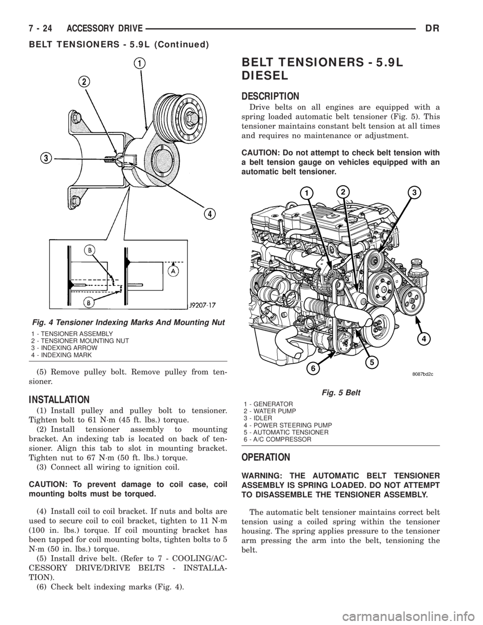
(6) Check belt indexing marks (Fig. 4).
BELT TENSIONERS - 5.9L
DIESEL
DESCRIPTION
Drive belts on all engines are equipped with a
spring loaded automatic belt tensioner (Fig. 5). This
tensioner maintains constant belt tension at all times
and requires no maintenance or adjustment.
CAUTION: Do not attempt to check belt tension with
a belt tension gauge on vehicles equipped with an
automatic belt tensioner.
OPERATION
WARNING: THE AUTOMATIC BELT TENSIONER
ASSEMBLY IS SPRING LOADED. DO NOT ATTEMPT
TO DISASSEMBLE THE TENSIONER ASSEMBLY.
The automatic belt tensioner maintains correct belt
tension using a coiled spring within the tensioner
housing. The spring applies pressure to the tensioner
arm pressing the arm into the belt, tensioning the
belt.
Fig. 4 Tensioner Indexing Marks And Mounting Nut
1 - TENSIONER ASSEMBLY
2 - TENSIONER MOUNTING NUT
3 - INDEXING ARROW
4 - INDEXING MARK
Fig. 5 Belt
1 - GENERATOR
2 - WATER PUMP
3 - IDLER
4 - POWER STEERING PUMP
5 - AUTOMATIC TENSIONER
6 - A/C COMPRESSOR
7 - 24 ACCESSORY DRIVEDR
BELT TENSIONERS - 5.9L (Continued)
Page 391 of 2895
the injector pulse width by turning the ground circuit
to each individual injector on and off.
²The PCM monitors the O2S sensor input and
adjusts air-fuel ratio. It also adjusts engine idle
speed through the idle air control (IAC) motor.
²The PCM adjusts ignition timing by turning the
ground path to the coil(s) on and off.
²The PCM operates the A/C compressor clutch
through the clutch relay. This happens if A/C has
been selected by the vehicle operator and requested
by the A/C thermostat.
ACCELERATION MODE
This is an Open Loop mode. The PCM recognizes
an abrupt increase in throttle position or MAP pres-
sure as a demand for increased engine output and
vehicle acceleration. The PCM increases injector
pulse width in response to increased throttle opening.
DECELERATION MODE
When the engine is at operating temperature, this
is an Open Loop mode. During hard deceleration, the
PCM receives the following inputs.
²Air conditioning select signal (if equipped)
²Air conditioning request signal (if equipped)
²Battery voltage
²Engine coolant temperature sensor
²Crankshaft position sensor
²Intake manifold air temperature sensor
²Manifold absolute pressure (MAP) sensor
²Throttle position sensor (TPS)
²Camshaft position sensor signal
²Park/neutral switch (gear indicator signalÐauto.
trans. only)
²Vehicle speed
If the vehicle is under hard deceleration with the
proper rpm and closed throttle conditions, the PCM
will ignore the oxygen sensor input signal. The PCM
will enter a fuel cut-off strategy in which it will not
supply a ground to the injectors. If a hard decelera-
tion does not exist, the PCM will determine the
proper injector pulse width and continue injection.
Based on the above inputs, the PCM will adjust
engine idle speed through the idle air control (IAC)
motor.
The PCM adjusts ignition timing by turning the
ground path to the coil on and off.
WIDE OPEN THROTTLE MODE
This is an Open Loop mode. During wide open
throttle operation, the PCM receives the following
inputs.
²Battery voltage
²Crankshaft position sensor
²Engine coolant temperature sensor
²Intake manifold air temperature sensor
²Manifold absolute pressure (MAP) sensor²Throttle position sensor (TPS)
²Camshaft position sensor signal
During wide open throttle conditions, the following
occurs:
²Voltage is applied to the fuel injectors with the
ASD relay via the PCM. The PCM will then control
the injection sequence and injector pulse width by
turning the ground circuit to each individual injector
on and off. The PCM ignores the oxygen sensor input
signal and provides a predetermined amount of addi-
tional fuel. This is done by adjusting injector pulse
width.
²The PCM adjusts ignition timing by turning the
ground path to the coil(s) on and off.
IGNITION SWITCH OFF MODE
When ignition switch is turned to OFF position,
the PCM stops operating the injectors, ignition coil,
ASD relay and fuel pump relay.
DESCRIPTION - 5 VOLT SUPPLIES
Two different Powertrain Control Module (PCM)
five volt supply circuits are used; primary and sec-
ondary.
DESCRIPTION - IGNITION CIRCUIT SENSE
This circuit ties the ignition switch to the Power-
train Control Module (PCM).
DESCRIPTION - POWER GROUNDS
The Powertrain Control Module (PCM) has 2 main
grounds. Both of these grounds are referred to as
power grounds. All of the high-current, noisy, electri-
cal devices are connected to these grounds as well as
all of the sensor returns. The sensor return comes
into the sensor return circuit, passes through noise
suppression, and is then connected to the power
ground.
The power ground is used to control ground cir-
cuits for the following PCM loads:
²Generator field winding
²Fuel injectors
²Ignition coil(s)
²Certain relays/solenoids
²Certain sensors
DESCRIPTION - SENSOR RETURN
The Sensor Return circuits are internal to the Pow-
ertrain Control Module (PCM).
Sensor Return provides a low±noise ground refer-
ence for all engine control system sensors. Refer to
Power Grounds for more information.
8E - 10 ELECTRONIC CONTROL MODULESDR
POWERTRAIN CONTROL MODULE (Continued)
Page 392 of 2895
OPERATION
OPERATION - PCM
The PCM operates the fuel system. The PCM is a
pre-programmed, triple microprocessor digital com-
puter. It regulates ignition timing, air-fuel ratio,
emission control devices, charging system, certain
transmission features, speed control, air conditioning
compressor clutch engagement and idle speed. The
PCM can adapt its programming to meet changing
operating conditions.
The PCM receives input signals from various
switches and sensors. Based on these inputs, the
PCM regulates various engine and vehicle operations
through different system components. These compo-
nents are referred to as Powertrain Control Module
(PCM) Outputs. The sensors and switches that pro-
vide inputs to the PCM are considered Powertrain
Control Module (PCM) Inputs.
The PCM adjusts ignition timing based upon
inputs it receives from sensors that react to: engine
rpm, manifold absolute pressure, engine coolant tem-
perature, throttle position, transmission gear selec-
tion (automatic transmission), vehicle speed, power
steering pump pressure, and the brake switch.
The PCM adjusts idle speed based on inputs it
receives from sensors that react to: throttle position,
vehicle speed, transmission gear selection, engine
coolant temperature and from inputs it receives from
the air conditioning clutch switch and brake switch.
Based on inputs that it receives, the PCM adjusts
ignition coil dwell. The PCM also adjusts the gener-
ator charge rate through control of the generator
field and provides speed control operation.
NOTE: PCM Inputs:
²ABS module (if equipped)
²A/C request (if equipped with factory A/C)
²A/C select (if equipped with factory A/C)
²A/C pressure transducer
²Auto shutdown (ASD) sense
²Battery temperature sensor
²Battery voltage
²Brake switch
²J1850 bus (+) circuits
²J1850 bus (-) circuits
²Camshaft position sensor signal
²Crankshaft position sensor
²Data link connection for DRB scan tool
²EATX module (if equipped)
²Engine coolant temperature sensor
²Fuel level (through J1850 circuitry)
²Generator (battery voltage) output
²Ignition circuit sense (ignition switch in on/off/
crank/run position)²Intake manifold air temperature sensor
²Knock sensors (2 on 3.7L engine)
²Leak detection pump (switch) sense (if equipped)
²Manifold absolute pressure (MAP) sensor
²Oil pressure
²Oxygen sensors
²Park/neutral switch (auto. trans. only)
²Power ground
²Power steering pressure switch (if equipped)
²Sensor return
²Signal ground
²Speed control multiplexed single wire input
²Throttle position sensor
²Transfer case switch (4WD range position)
²Vehicle speed signal
NOTE: PCM Outputs:
²A/C clutch relay
²Auto shutdown (ASD) relay
²J1850 bus (+/-) circuits for: speedometer, voltme-
ter, fuel gauge, oil pressure gauge/lamp, engine temp.
gauge and speed control warn. lamp
²Data link connection for DRB scan tool
²EGR valve control solenoid (if equipped)
²EVAP canister purge solenoid
²Five volt sensor supply (primary)
²Five volt sensor supply (secondary)
²Fuel injectors
²Fuel pump relay
²Generator field driver (-)
²Generator field driver (+)
²Idle air control (IAC) motor
²Ignition coil(s)
²Leak detection pump (if equipped)
²Malfunction indicator lamp (Check engine lamp).
Driven through J1850 circuits.
²Oxygen sensor heater relays
²Oxygen sensors (pulse width modulated)
²Radiator cooling fan relay (pulse width modu-
lated)
²Speed control vacuum solenoid
²Speed control vent solenoid
²Tachometer (if equipped). Driven through J1850
circuits.
²Transmission convertor clutch circuit. Driven
through J1850 circuits.
OPERATION - 5 VOLT SUPPLIES
Primary 5±volt supply:
²supplies the required 5 volt power source to the
Crankshaft Position (CKP) sensor.
²supplies the required 5 volt power source to the
Camshaft Position (CMP) sensor.
²supplies a reference voltage for the Manifold
Absolute Pressure (MAP) sensor.
DRELECTRONIC CONTROL MODULES 8E - 11
POWERTRAIN CONTROL MODULE (Continued)
Page 433 of 2895
STARTING
TABLE OF CONTENTS
page page
STARTING
DESCRIPTION.........................28
OPERATION...........................28
DIAGNOSIS AND TESTING - STARTING
SYSTEM............................29
SPECIFICATIONS
STARTING SYSTEM...................33
SPECIFICATIONS - TORQUE - STARTING
SYSTEM............................34
STARTER MOTOR
DIAGNOSIS AND TESTING - STARTER
MOTOR .............................34REMOVAL.............................34
INSTALLATION.........................37
STARTER MOTOR RELAY
DESCRIPTION.........................38
OPERATION...........................38
DIAGNOSIS AND TESTING - STARTER RELAY . 38
REMOVAL.............................39
INSTALLATION.........................39
STARTING
DESCRIPTION
The starting system consists of:
²Starter relay
²Starter motor (including an integral starter sole-
noid)
Other components to be considered as part of start-
ing system are:
²Battery
²Battery cables
²Ignition switch and key lock cylinder
²Clutch pedal position switch (manual transmis-
sion)
²Park/neutral position switch (automatic trans-
mission)
²Wire harnesses and connections.
The Battery, Starting, and Charging systems oper-
ate in conjunction with one another, and must be
tested as a complete system. For correct operation of
starting/charging systems, all components used in
these 3 systems must perform within specifications.
When attempting to diagnose any of these systems, it
is important that you keep their interdependency in
mind.
The diagnostic procedures used in each of these
groups include the most basic conventional diagnostic
methods, to the more sophisticated On-Board Diag-
nostics (OBD) built into the Powertrain Control Mod-
ule (PCM). Use of an induction-type milliampere
ammeter, volt/ohmmeter, battery charger, carbon pile
rheostat (load tester), and 12-volt test lamp may be
required.
Certain starting system components are monitored
by the PCM and may produce a Diagnostic TroubleCode (DTC). Refer to Diagnostic Trouble Codes in
Emission Control for a list of codes.OPERATION
The starting system components form two separate
circuits. A high-amperage feed circuit that feeds the
starter motor between 150 and 350 amperes (700
amperes - diesel engine), and a low-amperage control
circuit that operates on less than 20 amperes. The
high-amperage feed circuit components include the
battery, the battery cables, the contact disc portion of
the starter solenoid, and the starter motor. The low-
amperage control circuit components include the igni-
tion switch, the clutch pedal position switch (manual
transmission), the park/neutral position switch (auto-
matic transmission), the starter relay, the electro-
magnetic windings of the starter solenoid, and the
connecting wire harness components.
If the vehicle is equipped with a manual transmis-
sion, it has a clutch pedal position switch installed in
series between the ignition switch and the coil bat-
tery terminal of the starter relay. This normally open
switch prevents the starter relay from being ener-
gized when the ignition switch is turned to the Start
position, unless the clutch pedal is depressed. This
feature prevents starter motor operation while the
clutch disc and the flywheel are engaged. The starter
relay coil ground terminal is always grounded on
vehicles with a manual transmission.
If the vehicle is equipped with an automatic trans-
mission, battery voltage is supplied through the low-
amperage control circuit to the coil battery terminal
of the starter relay when the ignition switch is
turned to the Start position. The park/neutral posi-
tion switch is installed in series between the starter
relay coil ground terminal and ground. This normally
8F - 28 STARTINGDR
Page 434 of 2895
open switch prevents the starter relay from being
energized and the starter motor from operating
unless the automatic transmission gear selector is in
the Neutral or Park positions.
When the starter relay coil is energized, the nor-
mally open relay contacts close. The relay contacts
connect the relay common feed terminal to the relay
normally open terminal. The closed relay contacts
energize the starter solenoid coil windings.
The energized solenoid pull-in coil pulls in the sole-
noid plunger. The solenoid plunger pulls the shift
lever in the starter motor. This engages the starter
overrunning clutch and pinion gear with the starter
ring gear.
As the solenoid plunger reaches the end of its
travel, the solenoid contact disc completes the high-
amperage starter feed circuit and energizes the sole-
noid plunger hold-in coil. Current now flows between
the solenoid battery terminal and the starter motor,
energizing the starter.
Once the engine starts, the overrunning clutch pro-
tects the starter motor from damage by allowing thestarter pinion gear to spin faster than the pinion
shaft. When the ignition switch is released to the On
position, the starter relay coil is de-energized. This
causes the relay contacts to open. When the relay
contacts open, the starter solenoid plunger hold-in
coil is de-energized.
When the solenoid plunger hold-in coil is de-ener-
gized, the solenoid plunger return spring returns the
plunger to its relaxed position. This causes the con-
tact disc to open the starter feed circuit, and the shift
lever to disengage the overrunning clutch and pinion
gear from the starter ring gear.
DIAGNOSIS AND TESTING - STARTING
SYSTEM
The battery, starting, and charging systems oper-
ate in conjunction with one another, and must be
tested as a complete system. For correct starting/
charging system operation, all of the components
involved in these 3 systems must perform within
specifications.
Starting System Diagnosis
CONDITION POSSIBLE CAUSE CORRECTION
STARTER FAILS TO
OPERATE.1. Battery discharged or
faulty.1. Refer to Battery. Charge or replace battery, if required.
2. Starting circuit wiring
faulty.2. Refer to 8, Wiring Diagrams. Test and repair starter
feed and/or control circuits, if required.
3. Starter relay faulty. 3. Refer to Starter Relay in Diagnosis and Testing.
Replace starter relay if required.
4. Ignition switch faulty. 4. Refer to Ignition Switch and Key Lock Cylinder.
Replace ignition switch if required.
5. Clutch pedal position
switch faulty.5. Refer to Clutch Pedal Position Switch.
6. Park/Neutral position
switch faulty or
misadjusted.6. Refer to Park/Neutral Position Switch. Replace
park/neutral position switch if required.
7. Starter solenoid faulty. 7. Refer to Starter Motor. Replace starter motor assembly
if required.
8. Starter motor faulty. 8. If all other starting system components and circuits test
OK, replace starter motor.
STARTER ENGAGES,
FAILS TO TURN
ENGINE.1. Battery discharged or
faulty.1. Refer to Battery. Charge or replace battery if required.
2. Starting circuit wiring
faulty.2. Refer to 8, Wiring Diagrams. Test and repair starter
feed and/or control circuits if required.
3. Starter motor faulty. 3. If all other starting system components and circuits test
OK, replace starter motor assembly.
4. Engine seized. 4. Refer to Engine Diagnosis in the Diagnosis and Testing
section of 9, Engine.
DRSTARTING 8F - 29
STARTING (Continued)
Page 443 of 2895
STARTER MOTOR RELAY
DESCRIPTION
The starter relay is an electromechanical device
that switches battery current to the pull-in coil of the
starter solenoid when ignition switch is turned to
Start position. The starter relay is located in the
Power Distribution Center (PDC) in the engine com-
partment. See PDC cover for relay identification and
location.
The starter relay is a International Standards
Organization (ISO) relay. Relays conforming to ISO
specifications have common physical dimensions, cur-
rent capacities, terminal patterns, and terminal func-
tions.
The starter relay cannot be repaired or adjusted. If
faulty or damaged, it must be replaced.
OPERATION
The ISO relay consists of an electromagnetic coil, a
resistor or diode, and three (two fixed and one mov-
able) electrical contacts. The movable (common feed)
relay contact is held against one of the fixed contacts
(normally closed) by spring pressure. When electro-
magnetic coil is energized, it draws the movable con-
tact away from normally closed fixed contact, and
holds it against the other (normally open) fixed con-
tact.
When electromagnetic coil is de-energized, spring
pressure returns movable contact to normally closed
position. The resistor or diode is connected in parallel
with electromagnetic coil within relay, and helps to
dissipate voltage spikes produced when coil is de-en-
ergized.
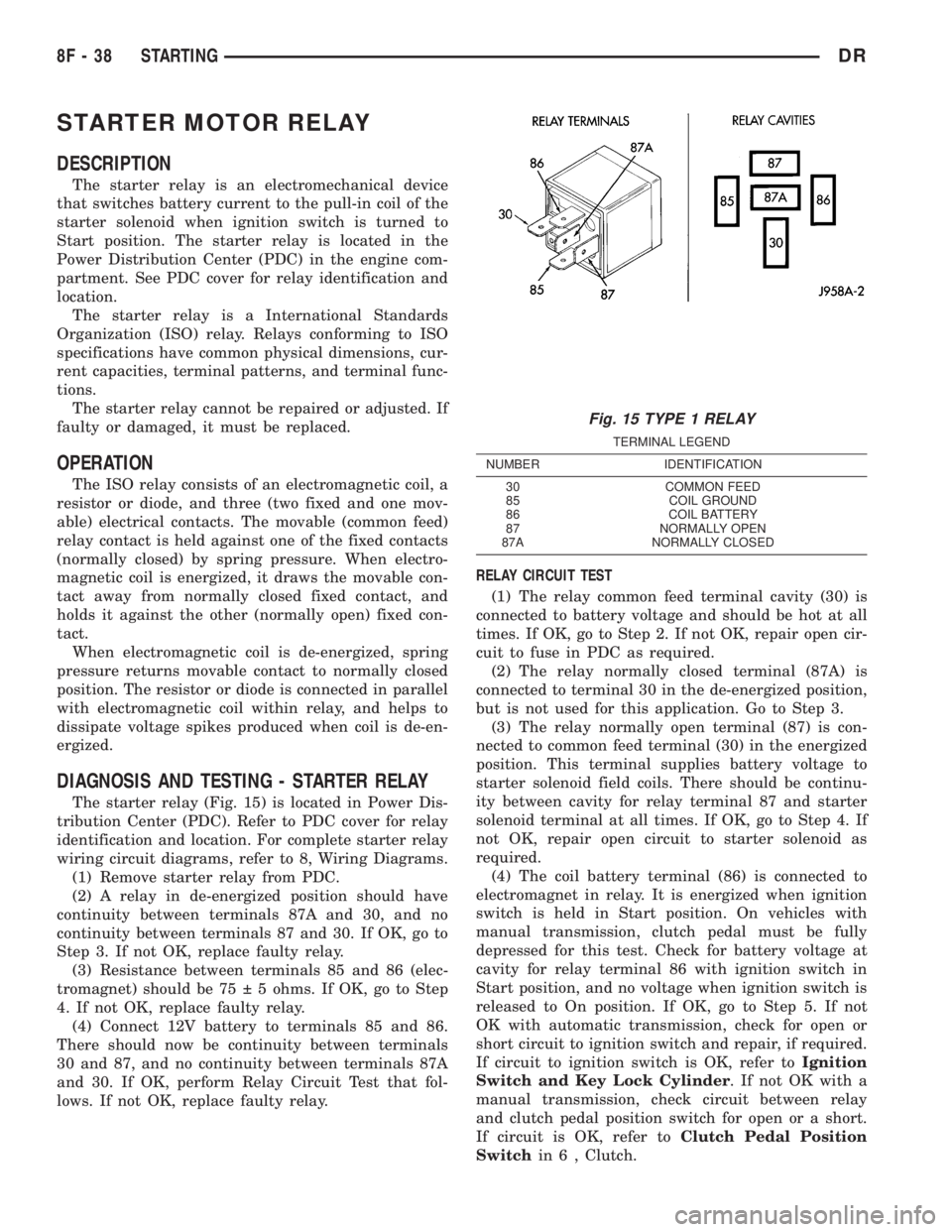
DIAGNOSIS AND TESTING - STARTER RELAY
The starter relay (Fig. 15) is located in Power Dis-
tribution Center (PDC). Refer to PDC cover for relay
identification and location. For complete starter relay
wiring circuit diagrams, refer to 8, Wiring Diagrams.
(1) Remove starter relay from PDC.
(2) A relay in de-energized position should have
continuity between terminals 87A and 30, and no
continuity between terminals 87 and 30. If OK, go to
Step 3. If not OK, replace faulty relay.
(3) Resistance between terminals 85 and 86 (elec-
tromagnet) should be 75 5 ohms. If OK, go to Step
4. If not OK, replace faulty relay.
(4) Connect 12V battery to terminals 85 and 86.
There should now be continuity between terminals
30 and 87, and no continuity between terminals 87A
and 30. If OK, perform Relay Circuit Test that fol-
lows. If not OK, replace faulty relay.RELAY CIRCUIT TEST
(1) The relay common feed terminal cavity (30) is
connected to battery voltage and should be hot at all
times. If OK, go to Step 2. If not OK, repair open cir-
cuit to fuse in PDC as required.
(2) The relay normally closed terminal (87A) is
connected to terminal 30 in the de-energized position,
but is not used for this application. Go to Step 3.
(3) The relay normally open terminal (87) is con-
nected to common feed terminal (30) in the energized
position. This terminal supplies battery voltage to
starter solenoid field coils. There should be continu-
ity between cavity for relay terminal 87 and starter
solenoid terminal at all times. If OK, go to Step 4. If
not OK, repair open circuit to starter solenoid as
required.
(4) The coil battery terminal (86) is connected to
electromagnet in relay. It is energized when ignition
switch is held in Start position. On vehicles with
manual transmission, clutch pedal must be fully
depressed for this test. Check for battery voltage at
cavity for relay terminal 86 with ignition switch in
Start position, and no voltage when ignition switch is
released to On position. If OK, go to Step 5. If not
OK with automatic transmission, check for open or
short circuit to ignition switch and repair, if required.
If circuit to ignition switch is OK, refer toIgnition
Switch and Key Lock Cylinder. If not OK with a
manual transmission, check circuit between relay
and clutch pedal position switch for open or a short.
If circuit is OK, refer toClutch Pedal Position
Switchin 6 , Clutch.
Fig. 15 TYPE 1 RELAY
TERMINAL LEGEND
NUMBER IDENTIFICATION
30 COMMON FEED
85 COIL GROUND
86 COIL BATTERY
87 NORMALLY OPEN
87A NORMALLY CLOSED
8F - 38 STARTINGDR
Page 458 of 2895
IGNITION CONTROL
TABLE OF CONTENTS
page page
IGNITION CONTROL
DESCRIPTION..........................1
SPECIFICATIONS
SPECIFICATIONS - TORQUE - IGNITION....3
ENGINE FIRING ORDER - 3.7L V-6.........4
ENGINE FIRING ORDER ± 4.7L V-8........4
FIRING ORDER / CABLE ROUTING ± 5.7L
V-8 ENGINE...........................4
ENGINE FIRING ORDER - 5.9L V-8.........4
SPARK PLUG CABLE ORDER ± 8.0L V-10
ENGINE..............................5
SPARK PLUG CABLE RESISTANCE........5
SPARK PLUGS........................5
IGNITION COIL RESISTANCE - 3.7L V-6.....6
IGNITION COIL RESISTANCE - 4.7L V-8.....6
IGNITION COIL RESISTANCE - 5.7L V-8.....6
IGNITION COIL RESISTANCE - 5.9L........6
IGNITION COIL RESISTANCE ± 8.0L V-10
ENGINE..............................6
IGNITION TIMING......................6
AUTOMATIC SHUT DOWN RELAY
DESCRIPTION - PCM OUTPUT.............6
OPERATION
OPERATION - PCM OUTPUT.............6
OPERATION - ASD SENSE - PCM INPUT....6
DIAGNOSIS AND TESTING - ASD AND FUEL
PUMP RELAYS........................7
REMOVAL.............................7
INSTALLATION..........................8
CAMSHAFT POSITION SENSOR
DESCRIPTION..........................8
OPERATION............................8
REMOVAL.............................11
INSTALLATION.........................14
DISTRIBUTOR
DESCRIPTION.........................16
OPERATION...........................16
REMOVAL.............................17INSTALLATION.........................18
DISTRIBUTOR CAP
DIAGNOSIS AND TESTING - DISTRIBUTOR
CAP - 5.9L V-8........................18
DISTRIBUTOR ROTOR
DIAGNOSIS AND TESTING - DISTRIBUTOR
ROTOR - 5.9L V-8.....................19
IGNITION COIL
DESCRIPTION.........................19
OPERATION...........................20
REMOVAL.............................23
INSTALLATION.........................24
KNOCK SENSOR
DESCRIPTION.........................25
OPERATION...........................25
REMOVAL.............................25
INSTALLATION.........................26
SPARK PLUG
DESCRIPTION.........................27
DIAGNOSIS AND TESTING - SPARK PLUG
CONDITIONS.........................27
REMOVAL.............................30
CLEANING
CLEANING AND ADJUSTMENT...........31
INSTALLATION.........................31
IGNITION COIL CAPACITOR
DESCRIPTION.........................33
OPERATION...........................33
REMOVAL.............................33
INSTALLATION.........................33
SPARK PLUG CABLE
DESCRIPTION.........................33
OPERATION...........................33
DIAGNOSIS AND TESTING - SPARK PLUG
CABLES............................33
REMOVAL.............................34
INSTALLATION.........................35
IGNITION CONTROL
DESCRIPTION
The ignition system is controlled by the Powertrain
Control Module (PCM) on all engines.
3.7L V-6 ENGINE
The 3.7L V-6 engine uses a separate ignition coil
for each cylinder. The one-piece coil bolts directly tothe cylinder head. Rubber boots seal the secondary
terminal ends of the coils to the top of all 6 spark
plugs. A separate electrical connector is used for each
coil.
Because of coil design, spark plug cables (second-
ary cables) are not used. A distributor is not used
with the 3.7L engine.
Two knock sensors (one for each cylinder bank) are
used to help control spark knock.
DRIGNITION CONTROL 8I - 1
Page 459 of 2895
The Auto Shutdown (ASD) relay provides battery
voltage to each ignition coil.
The ignition system consists of:
²6 Spark Plugs
²6 Separate Ignition Coils
²2 Knock Sensors
²Powertrain Control Module (PCM)
²Also to be considered part of the ignition system
are certain inputs from the Crankshaft Position,
Camshaft Position, Throttle Position, 2 knock and
MAP Sensors
4.7L V-8 ENGINE
The 4.7L V-8 engine uses a separate ignition coil for
each cylinder. The one-piece coil bolts directly to the
cylinder head. Rubber boots seal the secondary termi-
nal ends of the coils to the top of all 8 spark plugs. A
separate electrical connector is used for each coil.
Because of coil design, spark plug cables (second-
ary cables) are not used. A distributor is not used
with the 4.7L engine.
Two knock sensors (one for each cylinder bank) are
used to help control spark knock.
The Auto Shutdown (ASD) relay provides battery
voltage to each ignition coil.
The ignition system consists of:
²8 Spark Plugs
²8 Separate Ignition Coils
²2 Knock Sensors
²Powertrain Control Module (PCM)
²Also to be considered part of the ignition system
are certain inputs from the Crankshaft Position,
Camshaft Position, Throttle Position, 2 knock and
MAP Sensors
5.7L V-8 ENGINE
For additional information, also refer to Igni-
tion Coil Description and Operation.
The 5.7L V-8 engine is equipped with 16 spark
plugs. Two plugs are used for each cylinder. The 5.7L
is also equipped with 8 separate and independent
ignition coils. The one-piece coil bolts directly to the
cylinder head cover and attaches the coils secondary
output terminal directly to a spark plug using a rub-
ber boot seal. Each coil is also equipped with a sec-
ond output terminal. This second terminal connects a
conventional spark plug cable directly to a spark
plug on the opposite cylinder bank. A separate pri-
mary electrical connector is used for each coil.
Eight conventional spark plug cables are used with
the 5.7L. These cables connect a coil on one cylinder
bank, directly to a spark plug on the opposite cylin-
der bank. The cables are placed and routed in a spe-
cial plastic loom to keep them separated. This loom is
clipped to the intake manifold. To prevent a miss-
match of cables, a corresponding spark plug / coil
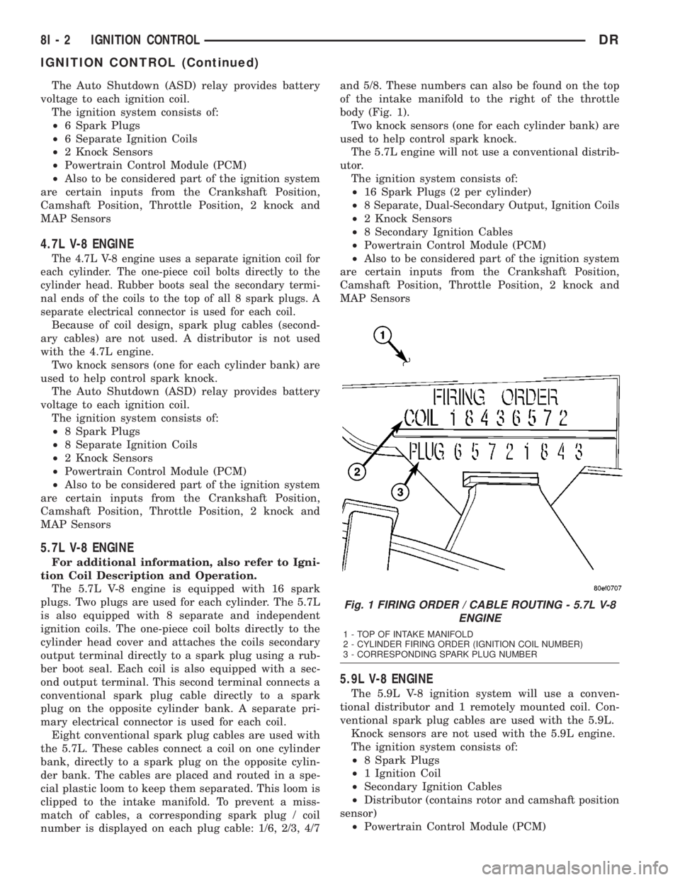
number is displayed on each plug cable: 1/6, 2/3, 4/7and 5/8. These numbers can also be found on the top
of the intake manifold to the right of the throttle
body (Fig. 1).
Two knock sensors (one for each cylinder bank) are
used to help control spark knock.
The 5.7L engine will not use a conventional distrib-
utor.
The ignition system consists of:
²16 Spark Plugs (2 per cylinder)
²
8 Separate, Dual-Secondary Output, Ignition Coils
²2 Knock Sensors
²8 Secondary Ignition Cables
²Powertrain Control Module (PCM)
²Also to be considered part of the ignition system
are certain inputs from the Crankshaft Position,
Camshaft Position, Throttle Position, 2 knock and
MAP Sensors
5.9L V-8 ENGINE
The 5.9L V-8 ignition system will use a conven-
tional distributor and 1 remotely mounted coil. Con-
ventional spark plug cables are used with the 5.9L.
Knock sensors are not used with the 5.9L engine.
The ignition system consists of:
²8 Spark Plugs
²1 Ignition Coil
²Secondary Ignition Cables
²Distributor (contains rotor and camshaft position
sensor)
²Powertrain Control Module (PCM)
Fig. 1 FIRING ORDER / CABLE ROUTING - 5.7L V-8
ENGINE
1 - TOP OF INTAKE MANIFOLD
2 - CYLINDER FIRING ORDER (IGNITION COIL NUMBER)
3 - CORRESPONDING SPARK PLUG NUMBER
8I - 2 IGNITION CONTROLDR
IGNITION CONTROL (Continued)
Page 460 of 2895
²Also to be considered part of the ignition system
are certain inputs from the Crankshaft Position, Cam-
shaft Position, Throttle Position and MAP Sensors
8.0L V-10 ENGINE
. The 8.0L V-10 engine is equipped with 2 remote
coil packs. Conventional spark plug cables are used
with the 8.0L engine. The 8.0L engine will not use a
conventional distributor
The ignition coils are individually fired, but each
coil is a dual output. Refer to Ignition Coil for addi-
tional information.Knock sensors are not used with the 8.0L engine.
The ignition system consists of:
²10 Spark Plugs
²2 Ignition Coil packs containing 10 individual
coils
²10 Secondary Ignition Cables
²Powertrain Control Module (PCM)
²Also to be considered part of the ignition system
are certain inputs from the Crankshaft Position,
Camshaft Position, Throttle Position and MAP Sen-
sors
SPECIFICATIONS
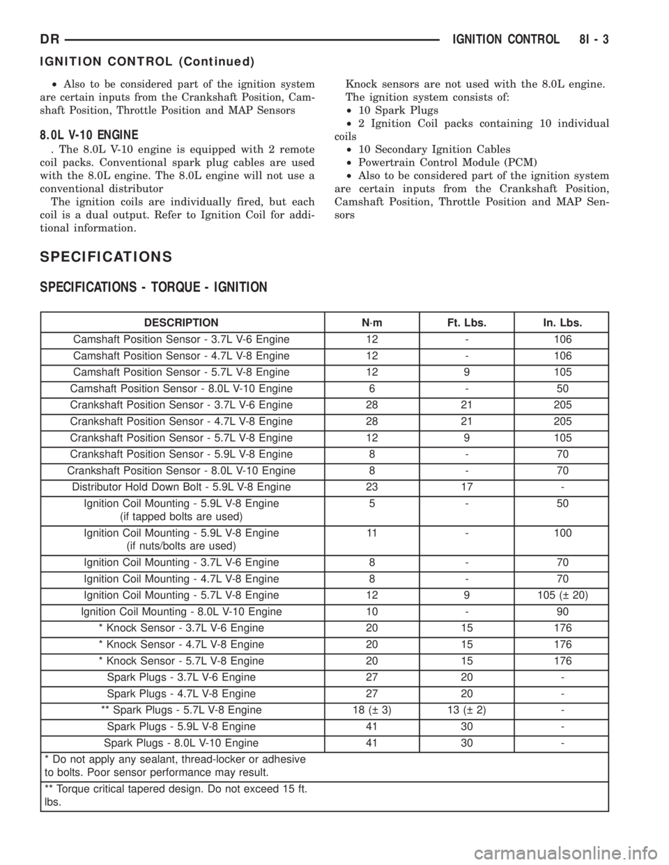
SPECIFICATIONS - TORQUE - IGNITION
DESCRIPTION N´m Ft. Lbs. In. Lbs.
Camshaft Position Sensor - 3.7L V-6 Engine 12 - 106
Camshaft Position Sensor - 4.7L V-8 Engine 12 - 106
Camshaft Position Sensor - 5.7L V-8 Engine 12 9 105
Camshaft Position Sensor - 8.0L V-10 Engine 6 - 50
Crankshaft Position Sensor - 3.7L V-6 Engine 28 21 205
Crankshaft Position Sensor - 4.7L V-8 Engine 28 21 205
Crankshaft Position Sensor - 5.7L V-8 Engine 12 9 105
Crankshaft Position Sensor - 5.9L V-8 Engine 8 - 70
Crankshaft Position Sensor - 8.0L V-10 Engine 8 - 70
Distributor Hold Down Bolt - 5.9L V-8 Engine 23 17 -
Ignition Coil Mounting - 5.9L V-8 Engine
(if tapped bolts are used)5-50
Ignition Coil Mounting - 5.9L V-8 Engine
(if nuts/bolts are used)11 - 100
Ignition Coil Mounting - 3.7L V-6 Engine 8 - 70
Ignition Coil Mounting - 4.7L V-8 Engine 8 - 70
Ignition Coil Mounting - 5.7L V-8 Engine 12 9 105 ( 20)
Ignition Coil Mounting - 8.0L V-10 Engine 10 - 90
* Knock Sensor - 3.7L V-6 Engine 20 15 176
* Knock Sensor - 4.7L V-8 Engine 20 15 176
* Knock Sensor - 5.7L V-8 Engine 20 15 176
Spark Plugs - 3.7L V-6 Engine 27 20 -
Spark Plugs - 4.7L V-8 Engine 27 20 -
** Spark Plugs - 5.7L V-8 Engine 18 ( 3) 13 ( 2) -
Spark Plugs - 5.9L V-8 Engine 41 30 -
Spark Plugs - 8.0L V-10 Engine 41 30 -
* Do not apply any sealant, thread-locker or adhesive
to bolts. Poor sensor performance may result.
** Torque critical tapered design. Do not exceed 15 ft.
lbs.
DRIGNITION CONTROL 8I - 3
IGNITION CONTROL (Continued)