skim DODGE RAM 2003 Service Repair Manual
[x] Cancel search | Manufacturer: DODGE, Model Year: 2003, Model line: RAM, Model: DODGE RAM 2003Pages: 2895, PDF Size: 83.15 MB
Page 382 of 2895
ELECTRONIC CONTROL MODULES
TABLE OF CONTENTS
page page
COMMUNICATION
DESCRIPTION..........................1
OPERATION............................2
CONTROLLER ANTILOCK BRAKE
DESCRIPTION..........................3
OPERATION............................3
REMOVAL.............................3
INSTALLATION..........................3
DATA LINK CONNECTOR
DESCRIPTION - DATA LINK CONNECTOR.....3
OPERATION - DATA LINK CONNECTOR......3
ENGINE CONTROL MODULE
DESCRIPTION - ECM.....................4
OPERATION - ECM......................4
REMOVAL.............................4
INSTALLATION..........................5
FRONT CONTROL MODULE
DESCRIPTION..........................5
OPERATION............................5
DIAGNOSIS AND TESTING - FRONT
CONTROL MODULE....................6
REMOVAL.............................6
INSTALLATION..........................6
HEATED SEAT MODULE
DESCRIPTION..........................6
OPERATION............................6
DIAGNOSIS AND TESTING - HEATED SEAT
MODULE.............................7
REMOVAL.............................7
INSTALLATION..........................7
POWERTRAIN CONTROL MODULE
DESCRIPTION
DESCRIPTION - PCM...................8DESCRIPTION - MODES OF OPERATION....8
DESCRIPTION - 5 VOLT SUPPLIES.......10
DESCRIPTION - IGNITION CIRCUIT SENSE . 10
DESCRIPTION - POWER GROUNDS......10
DESCRIPTION - SENSOR RETURN.......10
OPERATION
OPERATION - PCM....................11
OPERATION - 5 VOLT SUPPLIES.........11
OPERATION - IGNITION CIRCUIT SENSE . . . 12
REMOVAL.............................12
INSTALLATION.........................12
SENTRY KEY IMMOBILIZER MODULE
DESCRIPTION.........................13
OPERATION...........................13
STANDARD PROCEDURE - PCM/SKIM
PROGRAMMING......................14
REMOVAL.............................15
INSTALLATION.........................15
TRANSFER CASE CONTROL MODULE
DESCRIPTION.........................15
OPERATION...........................15
TRANSMISSION CONTROL MODULE
DESCRIPTION.........................19
OPERATION...........................19
STANDARD PROCEDURE
STANDARD PROCEDURE - TCM QUICK
LEARN..............................21
STANDARD PROCEDURE - DRIVE LEARN . . 21
COMMUNICATION
DESCRIPTION
The DaimlerChrysler Programmable Communica-
tion Interface (PCI) data bus system is a single wire
multiplex system used for vehicle communications on
many DaimlerChrysler Corporation vehicles. Multi-plexing is a system that enables the transmission of
several messages over a single channel or circuit. All
DaimlerChrysler vehicles use this principle for com-
munication between various microprocessor-based
electronic control modules. The PCI data bus exceeds
the Society of Automotive Engineers (SAE) J1850
Standard for Class B Multiplexing.
DRELECTRONIC CONTROL MODULES 8E - 1
Page 394 of 2895
(2) Tighten bolts. Refer to torque specifications.
(3) Check pin connectors in the PCM and the three
32±way connectors (four 38±way connectors if
equipped with NGC) for corrosion or damage. Also,
the pin heights in connectors should all be same.
Repair as necessary before installing connectors.
(4) Install three 32±way connectors (four 38±way
connectors if equipped with NGC).
(5) Install cover over electrical connectors. Cover
snaps onto PCM.
(6) Install negative battery cable.
(7) Use the DRB scan tool to reprogram new PCM
with vehicles original Vehicle Identification Number
(VIN) and original vehicle mileage.
SENTRY KEY IMMOBILIZER
MODULE
DESCRIPTION
The Sentry Key Immobilizer Module (SKIM) con-
tains a Radio Frequency (RF) transceiver and a cen-
tral processing unit, which includes the Sentry Key
Immobilizer System (SKIS) program logic. The SKIS
programming enables the SKIM to program and
retain in memory the codes of at least two, but no
more than eight electronically coded Sentry Key
transponders. The SKIS programming also enables
the SKIM to communicate over the Programmable
Communication Interface (PCI) bus network with the
Powertrain Control Module (PCM), and/or the
DRBIIItscan tool.
OPERATION
The SKIM transmits and receives RF signals
through a tuned antenna enclosed within a molded
plastic ring that is integral to the SKIM housing.
When the SKIM is properly installed on the steering
column, the antenna ring is oriented around the igni-
tion lock cylinder housing. This antenna ring must be
located within eight millimeters (0.31 inches) of the
Sentry Key in order to ensure proper RF communica-
tion between the SKIM and the Sentry Key tran-
sponder.
For added system security, each SKIM is pro-
grammed with a unique ªSecret Keyº code and a
security code. The SKIM keeps the ªSecret Keyº code
in memory. The SKIM also sends the ªSecret Keyº
code to each of the programmed Sentry Key tran-
sponders. The security code is used by the assembly
plant to access the SKIS for initialization, or by the
dealer technician to access the system for service.
The SKIM also stores in its memory the Vehicle
Identification Number (VIN), which it learns through
a PCI bus message from the PCM during initializa-
tion.The SKIM and the PCM both use software that
includes a rolling code algorithm strategy, which
helps to reduce the possibility of unauthorized SKIS
disarming. The rolling code algorithm ensures secu-
rity by preventing an override of the SKIS through
the unauthorized substitution of the SKIM or the
PCM. However, the use of this strategy also means
that replacement of either the SKIM or the PCM
units will require a system initialization procedure to
restore system operation.
When the ignition switch is turned to the ON or
START positions, the SKIM transmits an RF signal
to excite the Sentry Key transponder. The SKIM then
listens for a return RF signal from the transponder
of the Sentry Key that is inserted in the ignition lock
cylinder. If the SKIM receives an RF signal with
valid ªSecret Keyº and transponder identification
codes, the SKIM sends a ªvalid keyº message to the
PCM over the PCI bus. If the SKIM receives an
invalid RF signal or no response, it sends ªinvalid
keyº messages to the PCM. The PCM will enable or
disable engine operation based upon the status of the
SKIM messages.
The SKIM also sends messages to the Instrument
Cluster which controls the VTSS indicator LED. The
SKIM sends messages to the Instrument Cluster to
turn the LED on for about three seconds when the
ignition switch is turned to the ON position as a bulb
test. After completion of the bulb test, the SKIM
sends bus messages to keep the LED off for a dura-
tion of about one second. Then the SKIM sends mes-
sages to turn the LED on or off based upon the
results of the SKIS self-tests. If the VTSS indicator
LED comes on and stays on after the bulb test, it
indicates that the SKIM has detected a system mal-
function and/or that the SKIS has become inopera-
tive.
If the SKIM detects an invalid key when the igni-
tion switch is turned to the ON position, it sends
messages to flash the VTSS indicator LED. The
SKIM can also send messages to flash the LED as an
indication to the customer that the SKIS has been
placed in it's ªCustomer Learnº programming mode.
See Sentry Key Immobilizer System Transponder
Programming in this section for more information on
the ªCustomer Learnº programming mode.
For diagnosis or initialization of the SKIM and the
PCM, a DRBIIItscan tool and the proper Powertrain
Diagnostic Procedures manual are required. The
SKIM cannot be repaired and, if faulty or damaged,
the unit must be replaced.
DRELECTRONIC CONTROL MODULES 8E - 13
POWERTRAIN CONTROL MODULE (Continued)
Page 395 of 2895

STANDARD PROCEDURE - PCM/SKIM
PROGRAMMING
NOTE: There are two procedures for transfering the
secret key to the SKIM:
²When ONLY the SKIM module is replaced, the
secret key is transfered from the PCM to the SKIM.
The ORGINAL KEYS may then be programmed to
the SKIM.
²When ONLY the PCM is replaced, then the
secret key is transfered from the SKIM to the PCM.
The ORGINAL KEYS may be used.
²When BOTH the SKIM and the PCM are
replaced the secret key is transferred from the
SKIM to the PCM, and NEW KEYS must be pro-
grammed.
NOTE: Before replacing the Powertrain Control
Module (PCM) for a failed driver, control circuit, or
ground circuit, be sure to check the related compo-
nent/circuit integrity for failures not detected due to
a double fault in the circuit. Most PCM driver/con-
trol circuit failures are caused by internal compo-
nent failures (i.e. relay and solenoids) and shorted
circuits (i.e. pull-ups, drivers and switched circuits).
These failures are difficult to detect when a double
fault has occurred and only one Diagnostic Trouble
Code (DTC) has set.
When a PCM (SBEC) and the Sentry Key Immobi-
lizer Module (SKIM) are replaced at the same time
perform the following steps in order:
(1) Program the new PCM (SBEC).
(2) Program the new SKIM.
(3) Replace all ignition keys and program them to
the new SKIM.
PROGRAMMING THE PCM (SBEC)
The Sentry Key Immobilizer System (SKIS) Secret
Key is an ID code that is unique to each SKIM. This
code is programmed and stored in the SKIM, PCM
and transponder chip (ignition keys). When replacing
the PCM it is necessary to program the secret key
into the new PCM using the DRBIIItscan tool. Per-
form the following steps to program the secret key
into the PCM.
(1) Turn the ignition switch on (transmission in
park/neutral).
(2) Use the DRBIIItscan tool and select THEFT
ALARM, SKIM then MISCELLANEOUS.
(3) Select PCM REPLACED (GAS ENGINE).
(4) Enter secured access mode by entering the
vehicle four-digit PIN.
(5) Select ENTER to update PCM VIN.NOTE: If three attempts are made to enter secure
access mode using an incorrect PIN, secured
access mode will be locked out for one hour. To
exit this lockout mode, turn the ignition to the RUN
position for one hour then enter the correct PIN.
(Ensure all accessories are turned OFF. Also moni-
tor the battery state and connect a battery charger
if necessary).
(6) Press ENTER to transfer the secret key (the
SKIM will send the secret key to the PCM).
(7) Press Page Back to get to the Select System
menu and select ENGINE, MISCELLANEOUS, and
SRI MEMORY CHECK.
(8) The DRBIIItscan tool will ask, Is odometer
reading between XX and XX? Select the YES or NO
button on the DRB IIItscan tool. If NO is selected,
the DRBIIItscan tool will read, Enter odometer
Reading
reading from the instrument cluster and press
ENTER.
PROGRAMMING THE SKIM
(1) Turn the ignition switch on (transmission in
park/neutral).
(2) Use the DRBIIItscan tool and select THEFT
ALARM, SKIM then MISCELLANEOUS.
(3) Select SKIM REPLACED (GAS ENGINE).
(4) Program the vehicle four-digit PIN into SKIM.
(5) Select COUNTRY CODE and enter the correct
country.
NOTE: Be sure to enter the correct country code. If
the incorrect country code is programmed into the
SKIM, the SKIM must be replaced.
(6) Select YES to update the VIN (the SKIM will
learn the VIN from the PCM).
(7) Press ENTER to transfer the secret key (the
PCM will send the secret key information to the
SKIM).
(8) Program ignition keys to the SKIM.
NOTE: If the PCM and the SKIM are replaced at the
same time, all vehicle keys will need to be replaced
and programmed to the new SKIM.
PROGRAMMING IGNITION KEYS TO THE SKIM
(1) Turn the ignition switch on (transmission in
park/neutral).
(2) Use the DRBIIItscan tool and select THEFT
ALARM, SKIM then MISCELLANEOUS.
(3) Select PROGRAM IGNITION KEY'S.
(4) Enter secured access mode by entering the
vehicle four-digit PIN.
8E - 14 ELECTRONIC CONTROL MODULESDR
SENTRY KEY IMMOBILIZER MODULE (Continued)
Page 396 of 2895
NOTE: A maximum of eight keys can be learned to
each SKIM. Once a key is learned to a SKIM, it (the
key) cannot be transferred to another vehicle.
(5) If ignition key programming is unsuccessful,
the DRBIIItscan tool will display one of the follow-
ing messages:
(a) Programming Not Attempted - The DRBIIIt
scan tool attempts to read the programmed key
status and there are no keys programmed into
SKIM memory.
(b) Programming Key Failed (Possible Used Key
From Wrong Vehicle) - SKIM is unable to program
key due to one of the following:
²Faulty ignition key transponder.
²Ignition key is programmed to another vehicle.
(c) 8 Keys Already Learned, Programming Not
Done - SKIM transponder ID memory is full.
(6) Obtain ignition keys to be programmed from
customer (8 keys maximum).
(7) Using the DRBIIItscan tool, erase all ignition
keys by selecting MISCELLANEOUS and ERASE
ALL CURRENT IGN. KEYS.
(8) Program all ignition keys.
Learned Key In Ignition - Ignition key transponder
ID is currently programmed in SKIM memory.
REMOVAL
(1) Disconnect and isolate the battery negative
cable.
(2) Remove the steering column upper and lower
shrouds. Refer to Steering, Column, Shroud,
Removal.
(3) Disconnect the steering column wire harness
connector from the Sentry Key Immobilizer Module
(SKIM)
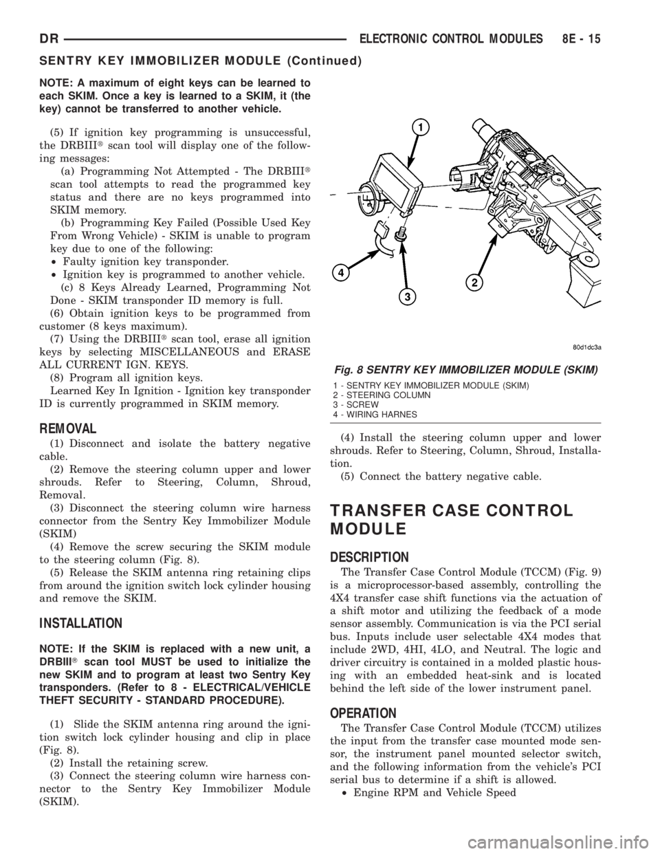
(4) Remove the screw securing the SKIM module
to the steering column (Fig. 8).
(5) Release the SKIM antenna ring retaining clips
from around the ignition switch lock cylinder housing
and remove the SKIM.
INSTALLATION
NOTE: If the SKIM is replaced with a new unit, a
DRBIIITscan tool MUST be used to initialize the
new SKIM and to program at least two Sentry Key
transponders. (Refer to 8 - ELECTRICAL/VEHICLE
THEFT SECURITY - STANDARD PROCEDURE).
(1) Slide the SKIM antenna ring around the igni-
tion switch lock cylinder housing and clip in place
(Fig. 8).
(2) Install the retaining screw.
(3) Connect the steering column wire harness con-
nector to the Sentry Key Immobilizer Module
(SKIM).(4) Install the steering column upper and lower
shrouds. Refer to Steering, Column, Shroud, Installa-
tion.
(5) Connect the battery negative cable.
TRANSFER CASE CONTROL
MODULE
DESCRIPTION
The Transfer Case Control Module (TCCM) (Fig. 9)
is a microprocessor-based assembly, controlling the
4X4 transfer case shift functions via the actuation of
a shift motor and utilizing the feedback of a mode
sensor assembly. Communication is via the PCI serial
bus. Inputs include user selectable 4X4 modes that
include 2WD, 4HI, 4LO, and Neutral. The logic and
driver circuitry is contained in a molded plastic hous-
ing with an embedded heat-sink and is located
behind the left side of the lower instrument panel.
OPERATION
The Transfer Case Control Module (TCCM) utilizes
the input from the transfer case mounted mode sen-
sor, the instrument panel mounted selector switch,
and the following information from the vehicle's PCI
serial bus to determine if a shift is allowed.
²Engine RPM and Vehicle Speed
Fig. 8 SENTRY KEY IMMOBILIZER MODULE (SKIM)
1 - SENTRY KEY IMMOBILIZER MODULE (SKIM)
2 - STEERING COLUMN
3 - SCREW
4 - WIRING HARNES
DRELECTRONIC CONTROL MODULES 8E - 15
SENTRY KEY IMMOBILIZER MODULE (Continued)
Page 502 of 2895

ajar indicator, high beam indicator, and turn signal
indicators operate based upon hard wired inputs to
the EMIC. The brake indicator is controlled by PCI
data bus messages from the Controller Antilock
Brake (CAB) as well as by hard wired park brake
switch inputs to the EMIC. The seatbelt indicator is
controlled by the EMIC programming, PCI data bus
messages from the Airbag Control Module (ACM),
and a hard wired seat belt switch input to the EMIC.
The Malfunction Indicator Lamp (MIL) is normally
controlled by PCI data bus messages from the Pow-
ertrain Control Module (PCM); however, if the EMIC
loses PCI data bus communication, the EMIC cir-
cuitry will automatically turn the MIL on until PCI
data bus communication is restored. The EMIC uses
PCI data bus messages from the Front Control Mod-
ule (FCM), the PCM, the diesel engine only Engine
Control Module (ECM), the ACM, the CAB, and the
Sentry Key Immobilizer Module (SKIM) to control all
of the remaining indicators.
The various EMIC indicators are controlled by dif-
ferent strategies; some receive fused ignition switch
output from the EMIC circuitry and have a switched
ground, while others are grounded through the EMIC
circuitry and have a switched battery feed. However,
all indicators are completely controlled by the EMIC
microprocessor based upon various hard wired and
electronic message inputs. All indicators are illumi-
nated at a fixed intensity, which is not affected by
the selected illumination intensity of the EMIC gen-
eral illumination lamps.
In addition, certain indicators in this instrument
cluster are automatically configured or self-config-
ured. This feature allows the configurable indicators
to be enabled by the EMIC circuitry for compatibility
with certain optional equipment. The EMIC defaults
for the ABS indicator and airbag indicator are
enabled, and these configuration settings must be
programmatically disabled in the EMIC using a
DRBIIItscan tool for vehicles that do not have this
equipment. The automatically configured or self-con-
figured indicators remain latent in each EMIC at all
times and will be active only when the EMIC
receives the appropriate PCI message inputs for that
optional system or equipment.
The hard wired indicator inputs may be diagnosed
using conventional diagnostic methods. However, the
EMIC circuitry and PCI bus message controlled indi-
cators are diagnosed using the EMIC self-diagnostic
actuator test. (Refer to 8 - ELECTRICAL/INSTRU-
MENT CLUSTER - DIAGNOSIS AND TESTING).
Proper testing of the PCI data bus and the electronic
message inputs to the EMIC that control an indicator
requires the use of a DRBIIItscan tool. Refer to the
appropriate diagnostic information. Specific details ofthe operation for each indicator may be found else-
where in this service information.
CLUSTER ILLUMINATION
The EMIC has several illumination lamps that are
illuminated when the exterior lighting is turned on
with the headlamp switch. The illumination intensity
of these lamps is adjusted when the interior lighting
thumbwheel on the headlamp switch is rotated (down
to dim, up to brighten) to one of six available minor
detent positions. The EMIC monitors a resistor mul-
tiplexed input from the headlamp switch on a dim-
mer input circuit. In response to that input, the
EMIC electronic circuitry converts a 12-volt input it
receives from a fuse in the Integrated Power Module
(IPM) on a hard wired panel lamps dimmer switch
signal circuit into a 12-volt Pulse Width Modulated
(PWM) output. The EMIC uses this PWM output to
power the cluster illumination lamps and the VFD
units on the EMIC circuit board, then provides a syn-
chronized PWM output on the various hard wired
fused panel lamps dimmer switch signal circuits to
control and synchronize the illumination intensity of
other incandescent illumination lamps in the vehicle.
The cluster illumination lamps are grounded at all
times.
The EMIC also sends electronic dimming level
messages over the PCI data bus to other electronic
modules in the vehicle to control and synchronize the
illumination intensity of their VFD units to that of
the EMIC VFD units. In addition, the thumbwheel
on the headlamp switch has a Parade Mode position
to provide a parade mode. The EMIC monitors the
request for this mode from the headlamp switch,
then sends an electronic dimming level message over
the PCI data bus to illuminate all VFD units in the
vehicle at full (daytime) intensity for easier visibility
when driving in daylight with the exterior lighting
turned on.
The hard wired headlamp switch and EMIC panel
lamps dimmer inputs and outputs may be diagnosed
using conventional diagnostic methods. However,
proper testing of the PWM output of the EMIC and
the electronic dimming level messages sent by the
EMIC over the PCI data bus requires the use of a
DRBIIItscan tool. Refer to the appropriate diagnos-
tic information.
INPUT AND OUTPUT CIRCUITS
HARD WIRED INPUTS
The hard wired inputs to the EMIC include the fol-
lowing:
²Brake Lamp Switch Output
²Driver Cylinder Lock Switch Sense
²Driver Door Ajar Switch Sense
DRINSTRUMENT CLUSTER 8J - 9
INSTRUMENT CLUSTER (Continued)
Page 507 of 2895
INSTRUMENT CLUSTER FAILURE MESSAGE
Fault Code Description Correction
AD FCM messages not received. Refer to the appropriate diagnostic information.
AE ACM messages not received. Refer to the appropriate diagnostic information.
AF SKIM messages not received. Refer to the appropriate diagnostic information.
B0 RKE fob batteries low. Refer to the appropriate diagnostic information.
B1 RKE module communication link. Refer to the appropriate diagnostic information.
00 Done All Diagnostic Trouble Codes (DTC) have been
displayed.
(7) The actuator test is now completed. The instru-
ment cluster will automatically exit the self-diagnos-
tic mode and return to normal operation at the
completion of the test, if the ignition switch is turned
to the Off position during the test, or if a vehicle
speed message indicating that the vehicle is moving
is received from the PCM over the PCI data bus dur-
ing the test.
(8)
Go back to Step 1 to repeat the test, if necessary.
REMOVAL
WARNING: ON VEHICLES EQUIPPED WITH AIR-
BAGS, DISABLE THE SUPPLEMENTAL RESTRAINT
SYSTEM BEFORE ATTEMPTING ANY STEERING
WHEEL, STEERING COLUMN, DRIVER AIRBAG,
PASSENGER AIRBAG, SEAT BELT TENSIONER,
SIDE CURTAIN AIRBAG, OR INSTRUMENT PANEL
COMPONENT DIAGNOSIS OR SERVICE. DISCON-
NECT AND ISOLATE THE BATTERY NEGATIVE
(GROUND) CABLE, THEN WAIT TWO MINUTES FOR
THE SYSTEM CAPACITOR TO DISCHARGE BEFORE
PERFORMING FURTHER DIAGNOSIS OR SERVICE.
THIS IS THE ONLY SURE WAY TO DISABLE THE
SUPPLEMENTAL RESTRAINT SYSTEM. FAILURE TO
TAKE THE PROPER PRECAUTIONS COULD
RESULT IN ACCIDENTAL AIRBAG DEPLOYMENT
AND POSSIBLE PERSONAL INJURY.
(1) Disconnect and isolate the battery negative
cable.
(2) Remove the cluster bezel from the instrument
panel. (Refer to 23 - BODY/INSTRUMENT PANEL/
CLUSTER BEZEL - REMOVAL).
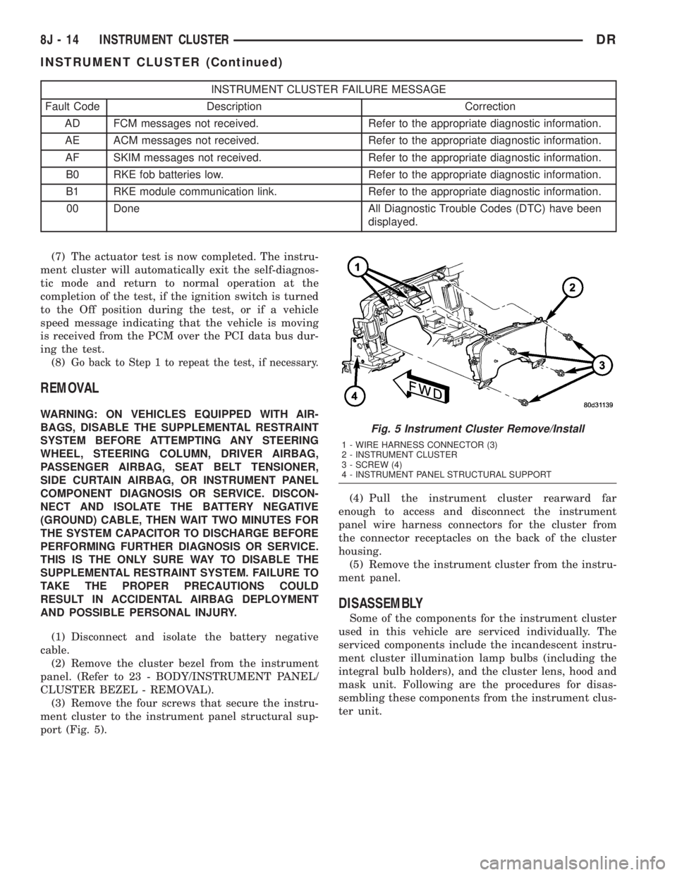
(3) Remove the four screws that secure the instru-
ment cluster to the instrument panel structural sup-
port (Fig. 5).(4) Pull the instrument cluster rearward far
enough to access and disconnect the instrument
panel wire harness connectors for the cluster from
the connector receptacles on the back of the cluster
housing.
(5) Remove the instrument cluster from the instru-
ment panel.
DISASSEMBLY
Some of the components for the instrument cluster
used in this vehicle are serviced individually. The
serviced components include the incandescent instru-
ment cluster illumination lamp bulbs (including the
integral bulb holders), and the cluster lens, hood and
mask unit. Following are the procedures for disas-
sembling these components from the instrument clus-
ter unit.
Fig. 5 Instrument Cluster Remove/Install
1 - WIRE HARNESS CONNECTOR (3)
2 - INSTRUMENT CLUSTER
3 - SCREW (4)
4 - INSTRUMENT PANEL STRUCTURAL SUPPORT
8J - 14 INSTRUMENT CLUSTERDR
INSTRUMENT CLUSTER (Continued)
Page 528 of 2895

nated. A red Light Emitting Diode (LED) behind the
cutout in the opaque layer of the overlay causes the
indicator to appear in red through the translucent
outer layer of the overlay when it is illuminated from
behind by the LED, which is soldered onto the
instrument cluster electronic circuit board. The secu-
rity indicator is serviced as a unit with the instru-
ment cluster.
OPERATION
The security indicator gives an indication to the
vehicle operator when the Vehicle Theft Security Sys-
tem (VTSS) is arming or is armed. On models
equipped with the Sentry Key Immobilizer System
(SKIS), the security indicator also gives an indication
to the vehicle operator of the status of the SKIS. This
indicator is controlled by a transistor on the instru-
ment cluster circuit board based upon cluster pro-
gramming, hard wired inputs to the cluster from the
various security system components, electronic mes-
sages received by the cluster from the Remote Key-
less Entry (RKE) receiver module over a dedicated
serial bus, and electronic messages received by the
cluster from the Sentry Key Immobilizer Module
(SKIM) over the Programmable Communications
Interface (PCI) data bus. The security indicator Light
Emitting Diode (LED) is completely controlled by the
instrument cluster logic circuit, and that logic will
allow this indicator to operate whenever the instru-
ment cluster receives a battery current input on the
fused B(+) circuit. Therefore, the LED can be illumi-
nated regardless of the ignition switch position. The
LED only illuminates when it is provided a path to
ground by the instrument cluster transistor. The
instrument cluster will turn on the security indicator
for the following reasons:
²Bulb Test- Each time the ignition switch is
turned to the On position, the SKIM tells the cluster
to illuminate the SKIS indicator for about two sec-
onds as a bulb test.
²VTSS Indication- During the sixteen second
VTSS arming function, the cluster will flash the
security indicator on and off repeatedly at a steady,
fast rate to indicate that the VTSS is in the process
of arming. Following successful VTSS arming, the
cluster flashes the security indicator on and off con-
tinuously at a slower rate to indicate that the VTSS
is armed. The security indicator continues flashing at
the slower rate until the VTSS is disarmed or trig-
gered. If the VTSS has alarmed and rearmed, the
cluster will flash the security indicator at a steady,
slow rate for about thirty seconds after the VTSS is
disarmed.
²SKIM Lamp-On Message- Each time the clus-
ter receives a lamp-on message from the SKIM, the
security indicator will be illuminated. The indicatorcan be flashed on and off, or illuminated solid, as dic-
tated by the SKIM message. The indicator remains
illuminated solid or continues to flash until the clus-
ter receives a lamp-off message from the SKIM, or
until the ignition switch is turned to the Off position,
whichever occurs first. For more information on the
SKIS and the security indicator control parameters,
(Refer to 8 - ELECTRICAL/VEHICLE THEFT SECU-
RITY/SENTRY KEY IMMOBILIZER SYSTEM -
OPERATION).
²Communication Error- If the cluster receives
no SKIS lamp-on or lamp-off messages from the
SKIM for twenty consecutive seconds, the SKIS indi-
cator is illuminated by the instrument cluster. The
indicator remains controlled and illuminated by the
cluster until a valid SKIS lamp-on or lamp-off mes-
sage is received from the SKIM.
²Actuator Test- Each time the instrument clus-
ter is put through the actuator test, the security indi-
cator will be turned on, then off again during the
bulb check portion of the test to confirm the function-
ality of the LED and the cluster control circuitry.
The instrument cluster circuitry controls the secu-
rity indicator whenever the ignition switch is in the
Off position and the VTSS is arming, armed, or
alarming. Whenever the ignition switch is in the On
or Start positions, the SKIM performs a self-test to
decide whether the SKIS is in good operating condi-
tion and whether a valid key is present in the igni-
tion lock cylinder. The SKIM then sends the proper
lamp-on or lamp-off messages to the instrument clus-
ter. For further diagnosis of the security indicator or
the instrument cluster circuitry that controls the
indicator, (Refer to 8 - ELECTRICAL/INSTRUMENT
CLUSTER - DIAGNOSIS AND TESTING). If the
instrument cluster flashes the SKIS indicator upon
ignition On, or turns on the SKIS indicator solid
after the bulb test, it indicates that a SKIS malfunc-
tion has occurred or that the SKIS is inoperative. For
proper diagnosis of the VTSS, the SKIS, the SKIM,
the PCI data bus, or the electronic message inputs to
the instrument cluster that control the security indi-
cator, a DRBIIItscan tool is required. Refer to the
appropriate diagnostic information.
SERVICE 4WD INDICATOR
DESCRIPTION
A service 4WD indicator is standard equipment on
all instrument clusters. However, on vehicles not
equipped with the optional four-wheel drive system
and electronically shifted transfer case, this indicator
is electronically disabled. The service 4WD indicator
consists of the words ªSERVICE 4x4º, which appears
in the lower portion of the odometer/trip odometer
DRINSTRUMENT CLUSTER 8J - 35
SECURITY INDICATOR (Continued)
Page 670 of 2895
VEHICLE THEFT SECURITY
TABLE OF CONTENTS
page page
VEHICLE THEFT SECURITY
DESCRIPTION
DESCRIPTION........................1
SENTRY KEY IMMOBILIZER SYSTEM (SKIS) . 1
DESCRIPTION........................1
OPERATION
OPERATION..........................2
OPERATION..........................2
OPERATION..........................2
DIAGNOSIS AND TESTING
VEHICLE THEFT SECURITY SYSTEM......3STANDARD PROCEDURE
CONFIGURING A NEW MODULE / SWITCH
OPERATING MODES....................3
SENTRY KEY IMMOBILIZER SYSTEM
INITIALIZATION........................3
SENTRY KEY IMMOBILIZER SYSTEM
TRANSPONDER PROGRAMMING..........4
SENTRY KEY IMMOBILIZER SYSTEM
INDICATOR LAMP
DESCRIPTION..........................5
OPERATION............................5
VEHICLE THEFT SECURITY
DESCRIPTION
DESCRIPTION
The Vehicle Theft/Security System (VTSS) is
designed to protect against whole vehicle theft. The
system monitors the vehicle doors and ignition for
unauthorized operation.
The VTSS activates:
²Sounding of the horn
²Flashing of the park lamps
²Flashing of the head lamps
The Remote Keyless Entry (RKE) has 1 mode of
operation,CUSTOMER USAGEmode. The cus-
tomer usage mode provides full functionality of the
module and is the mode in which the RKE module
should be operating when used by the customer.
SENTRY KEY IMMOBILIZER SYSTEM (SKIS)
The Sentry Key Immobilizer System (SKIS) is
designed to provide passive protection against unau-
thorized vehicle use by preventing the engine from
operating while the system is armed. The primary
components of this system are the Sentry Key Immo-
bilizer Module (SKIM), the Sentry Key transponder,
the Vehicle Theft/Security System (VTSS) indicator
LED, and the Powertrain Control Module (PCM).
The SKIM is installed on the steering column near
the ignition lock cylinder. The transponder is located
under the molded rubber cap on the head of the igni-tion key. The VTSS indicator LED is located in the
instrument cluster.
The SKIS includes two valid Sentry Key transpon-
ders from the factory. This is so the customer can self
program new keys if one is lost. If the customer
wishes, additional non-coded blank Sentry Keys are
available. These blank keys can be cut to match a
valid ignition key, but the engine will not start
unless the key transponder is also programmed to
the vehicle. The SKIS will recognize no more than
eight valid Sentry Key transponders at any one time.
The SKIS performs a self-test each time the igni-
tion switch is turned to the ON position, and will
store Diagnostic Trouble Codes (DTC's) if a system
malfunction is detected. The SKIS can be diagnosed,
and any stored DTC can be retrieved using a
DRBIIItscan tool as described in the proper Body
Diagnostic Procedures Manual.
DESCRIPTION
The Sentry Key Immobilizer Module (SKIM) con-
tains a Radio Frequency (RF) transceiver and a cen-
tral processing unit, which includes the Sentry Key
Immobilizer System (SKIS) program logic. The SKIS
programming enables the SKIM to program and
retain in memory the codes of at least two, but no
more than eight electronically coded Sentry Key
transponders. The SKIS programming also enables
the SKIM to communicate over the Programmable
Communication Interface (PCI) bus network with the
Powertrain Control Module (PCM), and/or the
DRBIIItscan tool.
DRVEHICLE THEFT SECURITY 8Q - 1
Page 671 of 2895
OPERATION
OPERATION
When in theCustomer Usagemode of operation,
the system is armed when the vehicle is locked using
the:
²Power Door Lock Switches
²Remote Keyless Entry (RKE) Transmitter
²Key Cylinder Switches
After the vehicle is locked and the last door is
closed, the VTSS indicator in the instrument cluster
will flash quickly for 16 seconds, indicating that the
arming is in process. After 16 seconds, the LED will
continue to flash at a slower rate indicating that the
system is armed.
VTSS disarming occurs upon normal vehicle entry
by unlocking either door via the key cylinder or RKE
transmitter, or by starting the vehicle with a valid
Sentry Key. This disarming will also halt the alarm
once it has been activated.
A tamper alert exists to notify the driver that the
system has been activated. This alert consists of 3
horn pulses and the security telltail flashing for 30
seconds when the vehicle is disarmed. The tamper
alert will not occur if disarmed while alarming.
The VTSS will not arm by mechanically locking the
vehicle doors. This will manually override the sys-
tem.
OPERATION
The SKIS includes two valid Sentry Key transpon-
ders from the factory. These two Sentry Keys can be
used to program additional non-coded blank Sentry
Keys. These blank keys can be cut to match a valid
ignition key, but the engine will not start unless the
key transponder is also programmed to the vehicle.
The SKIS will recognize no more than eight valid
Sentry Key transponders at any one time.
The SKIS performs a self-test each time the igni-
tion switch is turned to the ON position, and will
store Diagnostic Trouble Codes (DTC's) if a system
malfunction is detected. The SKIS can be diagnosed,
and any stored DTC can be retrieved using a
DRBIIItscan tool as described in the proper Power-
train Diagnostic Procedures manual.
OPERATION
The SKIM transmits and receives RF signals
through a tuned antenna enclosed within a molded
plastic ring formation that is integral to the SKIM
housing. When the SKIM is properly installed on the
steering column, the antenna ring is oriented around
the circumference of the ignition lock cylinder hous-
ing. This antenna ring must be located within eight
millimeters (0.31 inches) of the Sentry Key in orderto ensure proper RF communication between the
SKIM and the Sentry Key transponder.
For added system security, each SKIM is pro-
grammed with a unique ªSecret Keyº code and a
security code. The SKIM keeps the ªSecret Keyº code
in memory. The SKIM also sends the ªSecret Keyº
code to each of the programmed Sentry Key tran-
sponders. The security code is used by the assembly
plant to access the SKIS for initialization, or by the
dealer technician to access the system for service.
The SKIM also stores in its memory the Vehicle
Identification Number (VIN), which it learns through
a PCI bus message from the PCM during initializa-
tion.
The SKIM and the PCM both use software that
includes a rolling code algorithm strategy, which
helps to reduce the possibility of unauthorized SKIS
disarming. The rolling code algorithm ensures secu-
rity by preventing an override of the SKIS through
the unauthorized substitution of the SKIM or the
PCM. However, the use of this strategy also means
that replacement of either the SKIM or the PCM
units will require a system initialization procedure to
restore system operation.
When the ignition switch is turned to the ON or
START positions, the SKIM transmits an RF signal
to excite the Sentry Key transponder. The SKIM then
listens for a return RF signal from the transponder
of the Sentry Key that is inserted in the ignition lock
cylinder. If the SKIM receives an RF signal with
valid ªSecret Keyº and transponder identification
codes, the SKIM sends a ªvalid keyº message to the
PCM over the PCI bus. If the SKIM receives an
invalid RF signal or no response, it sends ªinvalid
keyº messages to the PCM. The PCM will enable or
disable engine operation based upon the status of the
SKIM messages.
The SKIM also sends messages to the Instrument
Cluster which controls the VTSS indicator. The
SKIM sends messages to the Instrument Cluster to
turn the indicator on for about three seconds when
the ignition switch is turned to the ON position as a
ªbulbº test. After completion of the ªbulbº test, the
SKIM sends bus messages to keep the indicator off
for a duration of about one second. Then the SKIM
sends messages to turn the indicator on or off based
upon the results of the SKIS self-tests. If the VTSS
indicator comes on and stays on after the ªbulb testº,
it indicates that the SKIM has detected a system
malfunction and/or that the SKIS has become inoper-
ative.
If the SKIM detects an invalid key when the igni-
tion switch is turned to the ON position, it sends
messages to flash the VTSS indicator. The SKIM can
also send messages to flash the indicator to serve as
an indication to the customer that the SKIS has been
8Q - 2 VEHICLE THEFT SECURITYDR
VEHICLE THEFT SECURITY (Continued)
Page 672 of 2895
placed in its ªCustomer Learnº programming mode.
See Sentry Key Immobilizer System Transponder
Programming in this section for more information on
the ªCustomer Learnº programming mode.
For diagnosis or initialization of the SKIM and the
PCM, a DRBIIItscan tool and the proper Powertrain
Diagnostic Procedures manual are required. The
SKIM cannot be repaired and, if faulty or damaged,
the unit must be replaced.
DIAGNOSIS AND TESTING
VEHICLE THEFT SECURITY SYSTEM
WARNING: ON VEHICLES EQUIPPED WITH AIR-
BAGS, REFER TO RESTRAINT SYSTEMS BEFORE
ATTEMPTING ANY STEERING WHEEL, STEERING
COLUMN, OR INSTRUMENT PANEL COMPONENT
DIAGNOSIS OR SERVICE. FAILURE TO TAKE THE
PROPER PRECAUTIONS COULD RESULT IN ACCI-
DENTAL AIRBAG DEPLOYMENT AND POSSIBLE
PERSONAL INJURY.
NOTE: The most reliable, efficient, and accurate
means to diagnose the Vehicle Theft Security Sys-
tem (VTSS) and Sentry Key Immobilizer System
(SKIS) involves the use of a DRBlllTscan tool and
the proper Powertrain Diagnostic Procedures man-
ual.
The Vehicle Theft Security System (VTSS), Sentry
Key Immobilizer System (SKIS) and the Programma-
ble Communication Interface (PCI) bus network
should be diagnosed using a DRBIIItscan tool. The
DRBIIItwill allow confirmation that the PCI bus is
functional, that the Sentry Key Immobilizer Module
(SKIM) is placing the proper messages on the PCI
bus, and that the Powertrain Control Module (PCM)
and the Instrument Cluster are receiving the PCI
bus messages. Refer to the proper Powertrain or
Body Diagnostic Procedures manual.
Visually inspect the related wiring harness connec-
tors. Look for broken, bent, pushed out or corroded
terminals. If any of the conditions are present, repair
as necessary. Refer to Wiring Diagrams for complete
circuit descriptions and diagrams. Refer to (Refer to
8 - ELECTRICAL/ELECTRONIC CONTROL MOD-
ULES/SENTRY KEY IMMOBILIZER MODULE -
REMOVAL) for SKIM replacement.
STANDARD PROCEDURE
CONFIGURING A NEW MODULE / SWITCH
OPERATING MODES
To configure a new module or to switch operating
modes, a DRBIIItscan tool must be used.
(1) Hook up the DRBIIItscan tool to the Data
Link Connector (DLC).
(2) With the key in the ignition, turn the key to
the RUN position.
(3) After the DRBIIItscan tool initialization, per-
form the following:
(a) Select ªTheft Alarm.º
(b) Select ªVTSS.º
(c) Select ªMiscellaneous.º
(4) Once in the ªMiscellaneousº screen:
(a) If you wish to configure a new module, select
ªConfigure Module.º
(b) If you wish to put the module into customer
usage mode, select ªEnable VTSS.º
(c) If you wish to put the module into dealer lot
mode, select ªDealer Lot.º
SENTRY KEY IMMOBILIZER SYSTEM
INITIALIZATION
The Sentry Key Immobilizer System (SKIS) initial-
ization should be performed following a Sentry Key
Immobilizer Module (SKIM) replacement.
It can be summarized by the following:
(1) Obtain the vehicles unique PIN number
assigned to it's original SKIM from the vehicle
owner, the vehicle's invoice or from Chrysler's Cus-
tomer Center.
(2) With the DRBIIItscan tool, select ªTheft
Alarm,º ªSKIM,º Miscellaneous.º Select ªSKIM Mod-
ule Replacedº function and the DRBIIItwill prompt
you through the following steps.
(3) Enter secured access mode using the unique
four digit PIN number.
(4) Program the vehicle's VIN number into the
SKIM's memory.
(5) Program the country code into the SKIM's
memory (U.S.).
(6) Transfer the vehicle's unique Secret Key data
from the PCM. This process will require the SKIM to
be insecured access mode. The PIN number must
be entered into the DRBIIItbefore the SKIM will
entersecured access mode. Oncesecured access
modeis active, the SKIM will remain in that mode
for 60 seconds.
(7) Program all customer keys into the SKIM's
memory. This required that the SKIM be insecured
access modeThe SKIM will immediately exit
secured access modeafter each key is pro-
grammed.
DRVEHICLE THEFT SECURITY 8Q - 3
VEHICLE THEFT SECURITY (Continued)