turn signal DODGE RAM 2003 Service Repair Manual
[x] Cancel search | Manufacturer: DODGE, Model Year: 2003, Model line: RAM, Model: DODGE RAM 2003Pages: 2895, PDF Size: 83.15 MB
Page 268 of 2895
DESCRIPTION N´m Ft. Lbs. In. Lbs.
RWAL Valve
Brake Line Fittings19 Ð 170
Rear Wheel Speed Sensor
Mounting Bolt24 Ð 200
FRONT WHEEL SPEED
SENSOR
DESCRIPTION
The ABS brake system uses 3 wheel speed sensors.
A sensor is mounted to each front hub/bearings. The
third sensor is mounted on top of the rear axle dif-
ferential housing.
OPERATION
The Wheel Speed Sensor consists of a magnet sur-
rounded by windings from a single strand of wire.
The sensor sends a small AC signal to the CAB. This
signal is generated by magnetic induction. The mag-
netic induction is created when a toothed sensor ring
(exciter ring or tone wheel) passes the stationary
magnetic WSS.
When the ring gear is rotated, the exciter ring
passes the tip of the WSS. As the exciter ring tooth
approaches the tip of the WSS, the magnetic lines of
force expand, causing the magnetic field to cut across
the sensor's windings. This, in turn causes current to
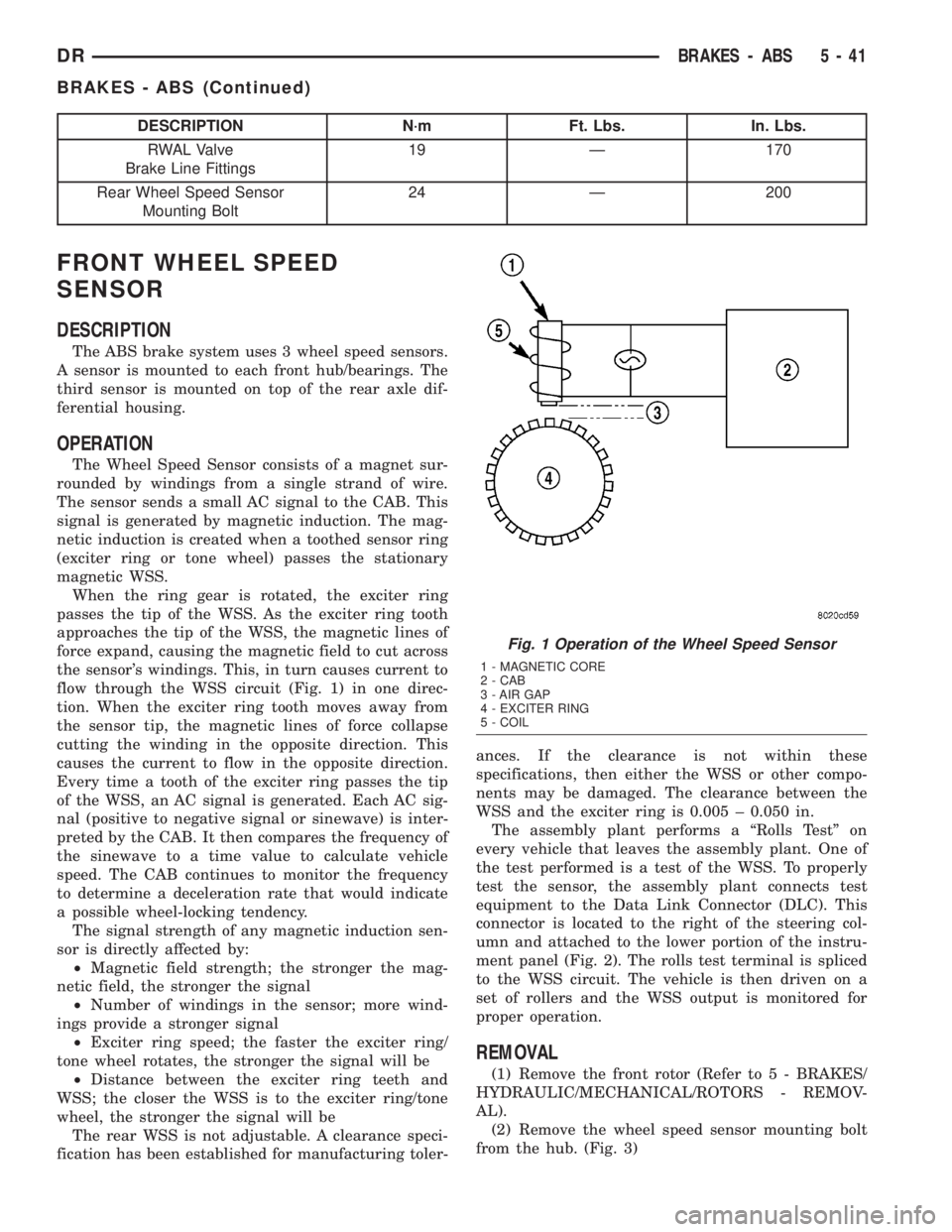
flow through the WSS circuit (Fig. 1) in one direc-
tion. When the exciter ring tooth moves away from
the sensor tip, the magnetic lines of force collapse
cutting the winding in the opposite direction. This
causes the current to flow in the opposite direction.
Every time a tooth of the exciter ring passes the tip
of the WSS, an AC signal is generated. Each AC sig-
nal (positive to negative signal or sinewave) is inter-
preted by the CAB. It then compares the frequency of
the sinewave to a time value to calculate vehicle
speed. The CAB continues to monitor the frequency
to determine a deceleration rate that would indicate
a possible wheel-locking tendency.
The signal strength of any magnetic induction sen-
sor is directly affected by:
²Magnetic field strength; the stronger the mag-
netic field, the stronger the signal
²Number of windings in the sensor; more wind-
ings provide a stronger signal
²Exciter ring speed; the faster the exciter ring/
tone wheel rotates, the stronger the signal will be
²Distance between the exciter ring teeth and
WSS; the closer the WSS is to the exciter ring/tone
wheel, the stronger the signal will be
The rear WSS is not adjustable. A clearance speci-
fication has been established for manufacturing toler-ances. If the clearance is not within these
specifications, then either the WSS or other compo-
nents may be damaged. The clearance between the
WSS and the exciter ring is 0.005 ± 0.050 in.
The assembly plant performs a ªRolls Testº on
every vehicle that leaves the assembly plant. One of
the test performed is a test of the WSS. To properly
test the sensor, the assembly plant connects test
equipment to the Data Link Connector (DLC). This
connector is located to the right of the steering col-
umn and attached to the lower portion of the instru-
ment panel (Fig. 2). The rolls test terminal is spliced
to the WSS circuit. The vehicle is then driven on a
set of rollers and the WSS output is monitored for
proper operation.
REMOVAL
(1) Remove the front rotor (Refer to 5 - BRAKES/
HYDRAULIC/MECHANICAL/ROTORS - REMOV-
AL).
(2) Remove the wheel speed sensor mounting bolt
from the hub. (Fig. 3)
Fig. 1 Operation of the Wheel Speed Sensor
1 - MAGNETIC CORE
2 - CAB
3 - AIR GAP
4 - EXCITER RING
5 - COIL
DRBRAKES - ABS 5 - 41
BRAKES - ABS (Continued)
Page 270 of 2895
INSTALLATION
(1) Connect the harness to the sensor.Be sure
the seal is securely in place between the sensor
and the wiring connector.
(2) Install the O-ring on the sensor (if removed).
(3) Insert the sensor in the differential housing.
(4) Install the sensor shield.
(5) Install the sensor mounting stud and tighten to
24 N´m (200 in. lbs.).
(6) Install the brake line on the sensor stud and
install the nut.
(7) Lower the vehicle.
TONE WHEEL
DIAGNOSIS AND TESTING - REAR WHEEL
SPEED SENSOR
Diagnosis of base brake conditions which are
mechanical in nature should be performed first. This
includes brake noise, lack of power assist, parking
brake, or vehicle vibration during normal braking.
The Antilock brake system performs several self-
tests every time the ignition switch is turned on and
the vehicle is driven. The CAB monitors the system
inputs and outputs circuits to verify the system is
operating properly. If the CAB senses a malfunction
in the system it will set a DTC into memory and trig-
ger the warning lamp.
NOTE: The MDS or DRB III scan tool is used to
diagnose the Antilock Brake system. For test proce-
dures refer to the Chassis Diagnostic Manual.
HYDRAULIC/MECHANICAL
DESCRIPTION - ELECTRONIC VARIABLE
BRAKE PROPORTIONING
Vehicles equipped with ABS use electronic variable
brake proportioning (EVBP) to balance front-to-rear
braking. The EVBP is used in place of a rear propor-
tioning valve. The EVBP system uses the ABS sys-
tem to control the slip of the rear wheels in partial
braking range. The braking force of the rear wheels
is controlled electronically by using the inlet and out-
let valves located in the integrated control unit
(ICU).
OPERATION - ELECTRONIC VARIABLE BRAKE
PROPORTIONING
EVBP is able to decrease, hold and increase rear
brake pressure without activating full ABS control.
Upon entry into EVBP the inlet valve for the rear
brake circuit is switched on so that the fluid supplyfrom the master cylinder is shut off. In order to
decrease the rear brake pressure, the outlet valve for
the rear brake circuit is pulsed. This allows fluid to
enter the low pressure accumulator (LPA) in the
hydraulic control unit (HCU) resulting in a drop in
fluid pressure to the rear brakes. In order to increase
the rear brake pressure, the outlet valve is switched
off and the inlet valve is pulsed. This increases the
pressure to the rear brakes.
The EVBP will remain functional during many
ABS fault modes. If both the red BRAKE and amber
ABS warning indicators are illuminated, the EVBP
may not be functioning.
HCU (HYDRAULIC CONTROL
UNIT)
DESCRIPTION
The HCU consists of a valve body, pump motor, low
pressure accumulators, inlet valves, outlet valves and
noise attenuators.
OPERATION
Accumulators in the valve body store extra fluid
released to the system for ABS mode operation. The
pump provides the fluid volume needed and is oper-
ated by a DC type motor. The motor is controlled by
the CAB.
The valves modulate brake pressure during
antilock braking and are controlled by the CAB.
The HCU provides three channel pressure control
to the front and rear brakes. One channel controls
the rear wheel brakes in tandem. The two remaining
channels control the front wheel brakes individually.
During antilock braking, the solenoid valves are
opened and closed as needed.
During normal braking, the HCU solenoid valves
and pump are not activated. The master cylinder and
power booster operate the same as a vehicle without
an ABS brake system.
NOTE: The three modes mentioned below do occur
but not necessarily in the order listed everytime.
During antilock braking, solenoid valve pressure
modulation occurs in three stages, pressure increase,
pressure hold, and pressure decrease. The valves are
all contained in the valve body portion of the HCU.
PRESSURE DECREASE
The outlet valve is opened and the inlet valve is
closed during the pressure decrease cycle.
A pressure decrease cycle is initiated when speed
sensor signals indicate high wheel slip at one or
more wheels. At this point, the CAB closes the inlet
DRBRAKES - ABS 5 - 43
REAR WHEEL SPEED SENSOR (Continued)
Page 331 of 2895
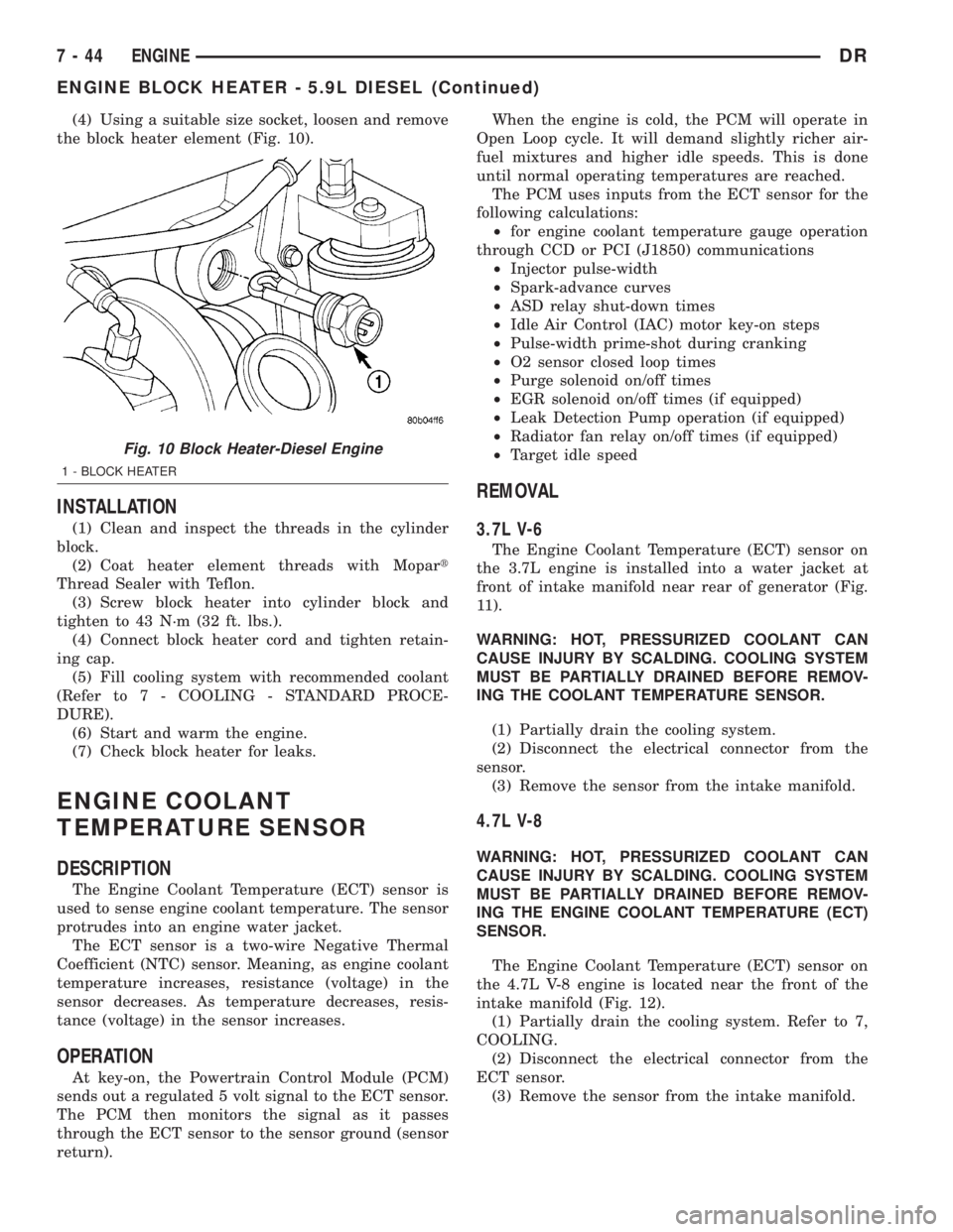
(4) Using a suitable size socket, loosen and remove
the block heater element (Fig. 10).
INSTALLATION
(1) Clean and inspect the threads in the cylinder
block.
(2) Coat heater element threads with Mopart
Thread Sealer with Teflon.
(3) Screw block heater into cylinder block and
tighten to 43 N´m (32 ft. lbs.).
(4) Connect block heater cord and tighten retain-
ing cap.
(5) Fill cooling system with recommended coolant
(Refer to 7 - COOLING - STANDARD PROCE-
DURE).
(6) Start and warm the engine.
(7) Check block heater for leaks.
ENGINE COOLANT
TEMPERATURE SENSOR
DESCRIPTION
The Engine Coolant Temperature (ECT) sensor is
used to sense engine coolant temperature. The sensor
protrudes into an engine water jacket.
The ECT sensor is a two-wire Negative Thermal
Coefficient (NTC) sensor. Meaning, as engine coolant
temperature increases, resistance (voltage) in the
sensor decreases. As temperature decreases, resis-
tance (voltage) in the sensor increases.
OPERATION
At key-on, the Powertrain Control Module (PCM)
sends out a regulated 5 volt signal to the ECT sensor.
The PCM then monitors the signal as it passes
through the ECT sensor to the sensor ground (sensor
return).When the engine is cold, the PCM will operate in
Open Loop cycle. It will demand slightly richer air-
fuel mixtures and higher idle speeds. This is done
until normal operating temperatures are reached.
The PCM uses inputs from the ECT sensor for the
following calculations:
²for engine coolant temperature gauge operation
through CCD or PCI (J1850) communications
²Injector pulse-width
²Spark-advance curves
²ASD relay shut-down times
²Idle Air Control (IAC) motor key-on steps
²Pulse-width prime-shot during cranking
²O2 sensor closed loop times
²Purge solenoid on/off times
²EGR solenoid on/off times (if equipped)
²Leak Detection Pump operation (if equipped)
²Radiator fan relay on/off times (if equipped)
²Target idle speed
REMOVAL
3.7L V-6
The Engine Coolant Temperature (ECT) sensor on
the 3.7L engine is installed into a water jacket at
front of intake manifold near rear of generator (Fig.
11).
WARNING: HOT, PRESSURIZED COOLANT CAN
CAUSE INJURY BY SCALDING. COOLING SYSTEM
MUST BE PARTIALLY DRAINED BEFORE REMOV-
ING THE COOLANT TEMPERATURE SENSOR.
(1) Partially drain the cooling system.
(2) Disconnect the electrical connector from the
sensor.
(3) Remove the sensor from the intake manifold.
4.7L V-8
WARNING: HOT, PRESSURIZED COOLANT CAN
CAUSE INJURY BY SCALDING. COOLING SYSTEM
MUST BE PARTIALLY DRAINED BEFORE REMOV-
ING THE ENGINE COOLANT TEMPERATURE (ECT)
SENSOR.
The Engine Coolant Temperature (ECT) sensor on
the 4.7L V-8 engine is located near the front of the
intake manifold (Fig. 12).
(1) Partially drain the cooling system. Refer to 7,
COOLING.
(2) Disconnect the electrical connector from the
ECT sensor.
(3) Remove the sensor from the intake manifold.
Fig. 10 Block Heater-Diesel Engine
1 - BLOCK HEATER
7 - 44 ENGINEDR
ENGINE BLOCK HEATER - 5.9L DIESEL (Continued)
Page 342 of 2895
occur when ambient (outside air temperature) is very
high.
²Engine loads and temperatures are high such as
when towing a trailer.
²Cool silicone fluid within the fan drive unit is
being redistributed back to its normal disengaged
(warm) position. This can occur during the first 15
seconds to one minute after engine start-up on a cold
engine.
LEAKS
Viscous fan drive operation is not affected by small
oil stains near the drive bearing. If leakage appears
excessive, replace the fan drive unit.
VISCOUS DRIVE
If the fan assembly free-wheels without drag (the
fan blades will revolve more than five turns when
spun by hand), replace the fan drive. This spin test
must be performed when the engine is cool.
For the following test, the cooling system must be
in good condition. It also will ensure against exces-
sively high coolant temperature.
WARNING: BE SURE THAT THERE IS ADEQUATE
FAN BLADE CLEARANCE BEFORE DRILLING.
(1) Drill a 3.18-mm (1/8-in) diameter hole in the
top center of the fan shroud.
(2) Obtain a dial thermometer with an 8 inch stem
(or equivalent). It should have a range of -18É-to-
105ÉC (0É-to-220É F). Insert thermometer through the
hole in the shroud. Be sure that there is adequate
clearance from the fan blades.
(3) Connect a tachometer and an engine ignition
timing light. The timing light is to be used as a
strobe light. This step cannot be used on the diesel
engine.
(4) Block the air flow through the radiator. Secure
a sheet of plastic in front of the radiator. Use tape at
the top to secure the plastic and be sure that the air
flow is blocked.
(5) Be sure that the air conditioner (if equipped) is
turned off.
WARNING: USE EXTREME CAUTION WHEN THE
ENGINE IS OPERATING. DO NOT STAND IN A
DIRECT LINE WITH THE FAN. DO NOT PUT YOUR
HANDS NEAR THE PULLEYS, BELTS OR FAN. DO
NOT WEAR LOOSE CLOTHING.
(6) Start the engine and operate at 2400 rpm.
Within ten minutes the air temperature (indicated on
the dial thermometer) should be up to 88É C (190É F).
Fan driveengagementshould start to occur at/be-
tween:
²3.7L Automatic Ð 93É C - 99ÉC (200É F - 210É F)²3.7L Manual/4.7L Automatic/5.9L Ð 85É to 91É C
(185É to 195É F)
²4.7L Manual Ð 74É to 79É C (165É to 175É F)
²Engagement is distinguishable by a definite
increasein fan flow noise (roaring). The timing light
also will indicate an increase in the speed of the fan.
(7) When viscous drive engagement is verified,
remove the plastic sheet. Fan drivedisengagement
should start to occur at or between:
²3.7L Automatic Ð 76ÉC to 81ÉC (168É F to 178É
F)
²3.7L Manual/4.7L Auto/ 5.9L Ð 67ÉC to 73ÉC
(153É F to 163É F)
²4.7L Manual Ð 56ÉC to 62ÉC (133É F to 143É F)
²8.0L engine Ð 88É to 96É C (190É to 205É F) A
definitedecreaseof fan flow noise (roaring) should
be noticed. If not, replace the defective viscous fan
drive unit.
CAUTION: Some engines equipped with serpentine
drive belts have reverse rotating fans and viscous
fan drives. They are marked with the word
REVERSE to designate their usage. Installation of
the wrong fan or viscous fan drive can result in
engine overheating.
CAUTION: If the viscous fan drive is replaced
because of mechanical damage, the cooling fan
blades should also be inspected. Inspect for fatigue
cracks, loose blades, or loose rivets that could
have resulted from excessive vibration. Replace fan
blade assembly if any of these conditions are
found. Also inspect water pump bearing and shaft
assembly for any related damage due to a viscous
fan drive malfunction.
FAN DRIVE VISCOUS CLUTCH
- 5.9L DIESEL
DESCRIPTION
The electronically controlled thermal viscous fan
drive (Fig. 31) is attached to the fan drive pulley
mounted to the engine. The coupling allows the fan
to be driven in a normal manner. The fan speed is
controlled by the electronic control module.
OPERATION
The Engine Control Module (ECM) controls the
level of engagment of the electronically controlled
viscous fan clutch by monitoring coolant tempera-
ture, intake manifold temperature, and air condition-
ing status. Based on cooling requirements, the ECM
sends a signal to the viscous fan clutch to increase or
decrease the fan speed.
DRENGINE 7 - 55
FAN DRIVE VISCOUS CLUTCH (Continued)
Page 366 of 2895
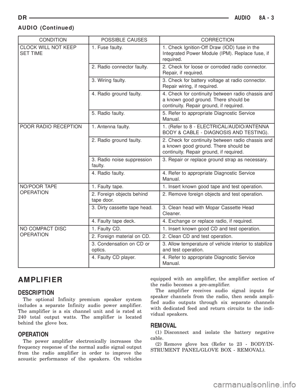
CONDITION POSSIBLE CAUSES CORRECTION
CLOCK WILL NOT KEEP
SET TIME1. Fuse faulty. 1. Check Ignition-Off Draw (IOD) fuse in the
Integrated Power Module (IPM). Replace fuse, if
required.
2. Radio connector faulty. 2. Check for loose or corroded radio connector.
Repair, if required.
3. Wiring faulty. 3. Check for battery voltage at radio connector.
Repair wiring, if required.
4. Radio ground faulty. 4. Check for continuity between radio chassis and
a known good ground. There should be
continuity. Repair ground, if required.
5. Radio faulty. 5. Refer to appropriate Diagnostic Service
Manual.
POOR RADIO RECEPTION 1. Antenna faulty. 1. (Refer to 8 - ELECTRICAL/AUDIO/ANTENNA
BODY & CABLE - DIAGNOSIS AND TESTING).
2. Radio ground faulty. 2. Check for continuity between radio chassis and
a known good ground. There should be
continuity. Repair ground, if required.
3. Radio noise suppression
faulty.3. Repair or replace ground strap as necessary.
4. Radio faulty. 4. Refer to appropriate Diagnostic Service
Manual.
NO/POOR TAPE
OPERATION1. Faulty tape. 1. Insert known good tape and test operation.
2. Foreign objects behind
tape door.2. Remove foreign objects and test operation.
3. Dirty cassette tape head. 3. Clean head with Mopar Cassette Head
Cleaner.
4. Faulty tape deck. 4. Exchange or replace radio, if required.
NO COMPACT DISC
OPERATION1. Faulty CD. 1. Insert known good CD and test operation.
2. Foreign material on CD. 2. Clean CD and test operation.
3. Condensation on CD or
optics.3. Allow temperature of vehicle interior to stabilize
and test operation.
4. Faulty CD player. 4. Refer to appropriate Diagnostic Service
Manual.
AMPLIFIER
DESCRIPTION
The optional Infinity premium speaker system
includes a separate Infinity audio power amplifier.
The amplifier is a six channel unit and is rated at
240 total output watts. The amplifier is located
behind the glove box.
OPERATION
The power amplifier electronically increases the
frequency response of the normal audio signal output
from the radio amplifier in order to improve the
acoustic performance of the speakers. On vehiclesequipped with an amplifier, the amplifier section of
the radio becomes a pre-amplifier.
The amplifier receives audio signal inputs for
speaker channels from the radio, then sends ampli-
fied audio outputs through six separate channels
with dedicated feed and return circuits to the indi-
vidual speakers.
REMOVAL
(1) Disconnect and isolate the battery negative
cable.
(2) Remove glove box (Refer to 23 - BODY/IN-
STRUMENT PANEL/GLOVE BOX - REMOVAL).
DRAUDIO 8A - 3
AUDIO (Continued)
Page 375 of 2895
REMOVAL
WARNING: DISABLE THE AIRBAG SYSTEM
BEFORE ATTEMPTING ANY STEERING WHEEL,
STEERING COLUMN, SEAT BELT TENSIONER, SIDE
AIRBAG, OR INSTRUMENT PANEL COMPONENT
DIAGNOSIS OR SERVICE. DISCONNECT AND ISO-
LATE THE BATTERY NEGATIVE (GROUND) CABLE,
THEN WAIT TWO MINUTES FOR THE AIRBAG SYS-
TEM CAPACITOR TO DISCHARGE BEFORE PER-
FORMING FURTHER DIAGNOSIS OR SERVICE. THIS
IS THE ONLY SURE WAY TO DISABLE THE AIRBAG
SYSTEM. FAILURE TO TAKE THE PROPER PRE-
CAUTIONS COULD RESULT IN ACCIDENTAL AIR-
BAG DEPLOYMENT AND POSSIBLE PERSONAL
INJURY.
(1) Disconnect and isolate the battery negative
cable.
(2) Remove the driver airbag from the vehicle
(Refer to 8 - ELECTRICAL/RESTRAINTS/DRIVER
AIRBAG - REMOVAL).
(3) Remove the speed control switches (Refer to 8 -
ELECTRICAL/SPEED CONTROL/SWITCH -
REMOVAL).
(4) Unplug the wire harness connector from the
remote radio switch(es).
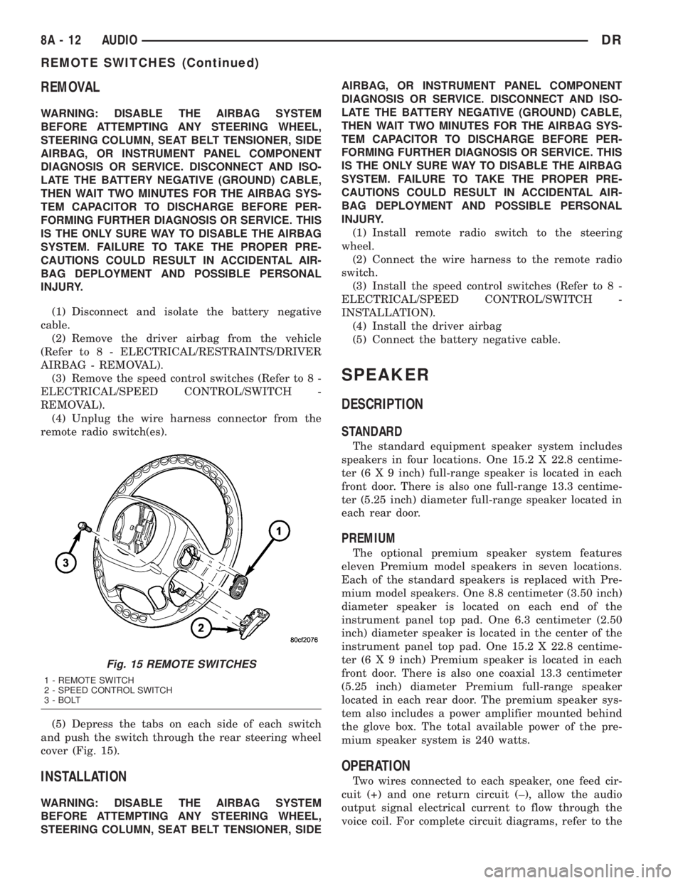
(5) Depress the tabs on each side of each switch
and push the switch through the rear steering wheel
cover (Fig. 15).
INSTALLATION
WARNING: DISABLE THE AIRBAG SYSTEM
BEFORE ATTEMPTING ANY STEERING WHEEL,
STEERING COLUMN, SEAT BELT TENSIONER, SIDEAIRBAG, OR INSTRUMENT PANEL COMPONENT
DIAGNOSIS OR SERVICE. DISCONNECT AND ISO-
LATE THE BATTERY NEGATIVE (GROUND) CABLE,
THEN WAIT TWO MINUTES FOR THE AIRBAG SYS-
TEM CAPACITOR TO DISCHARGE BEFORE PER-
FORMING FURTHER DIAGNOSIS OR SERVICE. THIS
IS THE ONLY SURE WAY TO DISABLE THE AIRBAG
SYSTEM. FAILURE TO TAKE THE PROPER PRE-
CAUTIONS COULD RESULT IN ACCIDENTAL AIR-
BAG DEPLOYMENT AND POSSIBLE PERSONAL
INJURY.
(1) Install remote radio switch to the steering
wheel.
(2) Connect the wire harness to the remote radio
switch.
(3) Install the speed control switches (Refer to 8 -
ELECTRICAL/SPEED CONTROL/SWITCH -
INSTALLATION).
(4) Install the driver airbag
(5) Connect the battery negative cable.
SPEAKER
DESCRIPTION
STANDARD
The standard equipment speaker system includes
speakers in four locations. One 15.2 X 22.8 centime-
ter (6 X 9 inch) full-range speaker is located in each
front door. There is also one full-range 13.3 centime-
ter (5.25 inch) diameter full-range speaker located in
each rear door.
PREMIUM
The optional premium speaker system features
eleven Premium model speakers in seven locations.
Each of the standard speakers is replaced with Pre-
mium model speakers. One 8.8 centimeter (3.50 inch)
diameter speaker is located on each end of the
instrument panel top pad. One 6.3 centimeter (2.50
inch) diameter speaker is located in the center of the
instrument panel top pad. One 15.2 X 22.8 centime-
ter (6 X 9 inch) Premium speaker is located in each
front door. There is also one coaxial 13.3 centimeter
(5.25 inch) diameter Premium full-range speaker
located in each rear door. The premium speaker sys-
tem also includes a power amplifier mounted behind
the glove box. The total available power of the pre-
mium speaker system is 240 watts.
OPERATION
Two wires connected to each speaker, one feed cir-
cuit (+) and one return circuit (±), allow the audio
output signal electrical current to flow through the
voice coil. For complete circuit diagrams, refer to the
Fig. 15 REMOTE SWITCHES
1 - REMOTE SWITCH
2 - SPEED CONTROL SWITCH
3 - BOLT
8A - 12 AUDIODR
REMOTE SWITCHES (Continued)
Page 380 of 2895
CHIME/BUZZER
TABLE OF CONTENTS
page page
CHIME/BUZZER
DESCRIPTION..........................1
OPERATION............................1DIAGNOSIS AND TESTING - CHIME
CONDITIONS..........................2
CHIME/BUZZER
DESCRIPTION
The chime module is located within the instrument
cluster and is not serviceable. The chime system pro-
vides the driver with warning chimes for:
²Air Bag
²Seat Belt
²Low Fuel
²Door Ajar
²Low Wash
²Park Brake
²Over Speed
²Turn Signal On
²Key-In Ignition
²Exterior Lamps ON
²Warning Lamp Announcement
²Transmission Over Temperature
OPERATION
FASTEN SEAT BELT
The seat belt reminder system uses both visual
and audible signals. The Instrument Cluster moni-
tors the driver seat belt buckle switch. When the
ignition switch transitions from OFF to RUN and the
driver seat belt has not been buckled, the Instrument
Cluster will illuminate the seat belt indicator lamp
and sound the chime. The system will always illumi-
nate the seat belt reminder lamp for four to eight
seconds when the ignition switch is turned to the ON
position. The CHIME will sound during the same
time interval if the driver's seat belt is not fastened.
The warning lamp will remain illuminated as long as
the seat belt remains unbuckled, and the ignition
switch is in the RUN position. Passenger seat belts
are not connected to the system.
HEADLAMPS REMINDER
The Instrument Cluster monitors the multiplex
headlamp switch. The headlamp audible warning will
alert the driver that the exterior lamps have been
left on. If the ignition switch is left off, the driver's
door open, and the headlamp switch is in the parklamp or headlamp position, the chime will sound
until the headlamp switch is turned off, the door is
closed or the battery protection time out expires.
KEY IN IGNITION REMINDER
The Instrument Cluster monitors the ignition
switch. The chime will activate if the drivers door is
opened and the key is in the ignition switch, with the
ignition switch in either the OFF, LOCK, or the
accessory (ACC) position. The chime will continue
until the key is removed from the ignition switch or
the door is closed.
DOOR AJAR CHIME
The Instrument Cluster monitors the door ajar
switches. A chime will sound once when the door is
opened, the ignition is in RUN position and vehicle
speed is present.
TURN SIGNAL ON
The Instrument Cluster monitors the multiplex
multifunction switch. The instrument cluster shall
remind the driver that either turn signal has been
left on by a continuous chime after the turn signal
indicator is left ON for 1.0 miles and the vehicle
speed is 15 mph or greater.
LOW FUEL REMINDER
When the fuel level drops to approximately 1/8
tank, the fuel symbol will light and a single chime
will sound. The light will remain on until fuel is
added.
OVER SPEED
During any ignition ON, the Instrument Cluster
maintains the most recently received speed. If the
vehicle speed exceeds a preprogramed limit set in the
instrument cluster it will activate a single chime.
WARNING LAMP ANNOUNCEMENT
The Instrument Cluster monitors critical engine
and transmission system parameters. If any of the
systems are out of their operating parameters, the
instrument cluster will illuminate a lamp and acti-
vate and audible chime.
DRCHIME/BUZZER 8B - 1
Page 385 of 2895
ENGINE CONTROL MODULE
DESCRIPTION - ECM
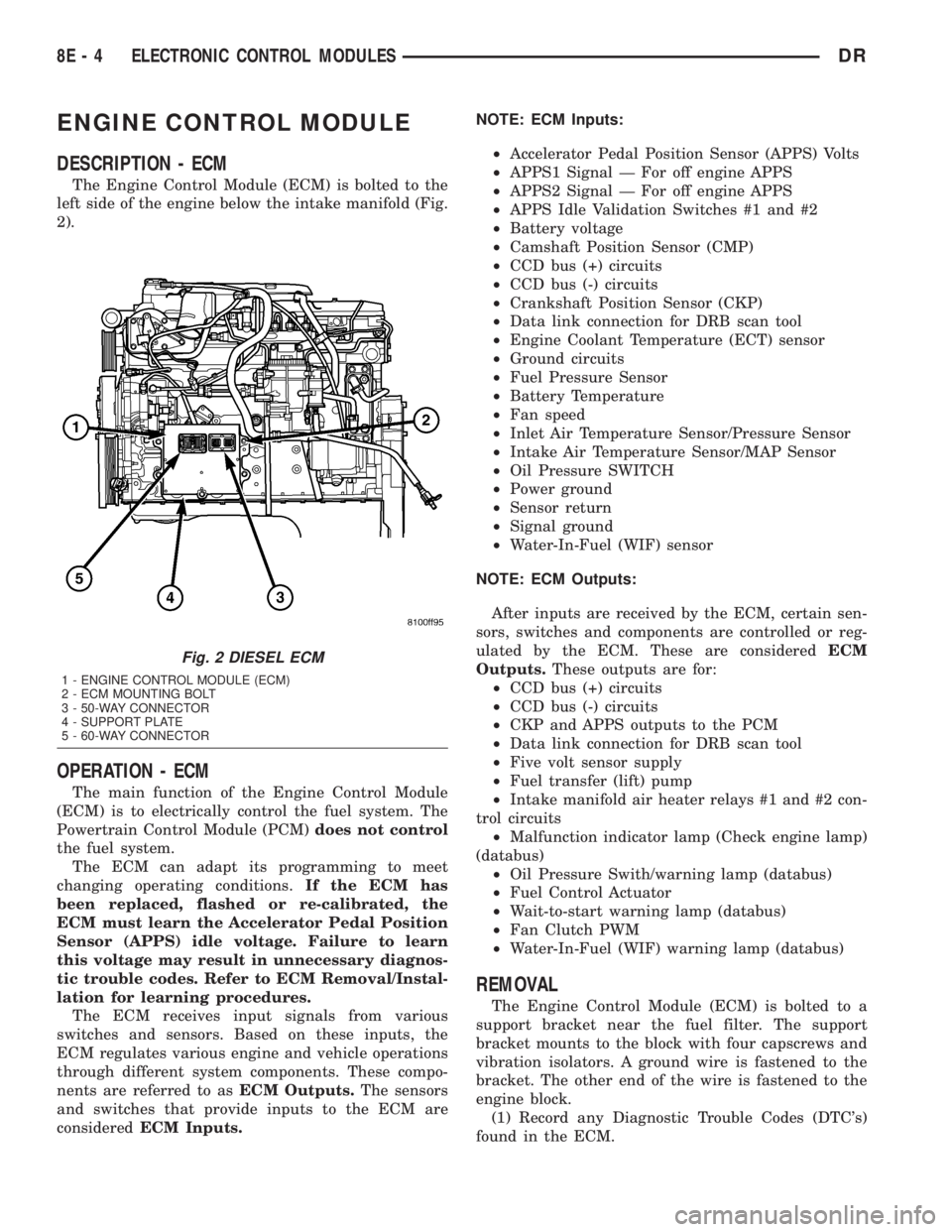
The Engine Control Module (ECM) is bolted to the
left side of the engine below the intake manifold (Fig.
2).
OPERATION - ECM
The main function of the Engine Control Module
(ECM) is to electrically control the fuel system. The
Powertrain Control Module (PCM)does not control
the fuel system.
The ECM can adapt its programming to meet
changing operating conditions.If the ECM has
been replaced, flashed or re-calibrated, the
ECM must learn the Accelerator Pedal Position
Sensor (APPS) idle voltage. Failure to learn
this voltage may result in unnecessary diagnos-
tic trouble codes. Refer to ECM Removal/Instal-
lation for learning procedures.
The ECM receives input signals from various
switches and sensors. Based on these inputs, the
ECM regulates various engine and vehicle operations
through different system components. These compo-
nents are referred to asECM Outputs.The sensors
and switches that provide inputs to the ECM are
consideredECM Inputs.NOTE: ECM Inputs:
²Accelerator Pedal Position Sensor (APPS) Volts
²APPS1 Signal Ð For off engine APPS
²APPS2 Signal Ð For off engine APPS
²APPS Idle Validation Switches #1 and #2
²Battery voltage
²Camshaft Position Sensor (CMP)
²CCD bus (+) circuits
²CCD bus (-) circuits
²Crankshaft Position Sensor (CKP)
²Data link connection for DRB scan tool
²Engine Coolant Temperature (ECT) sensor
²Ground circuits
²Fuel Pressure Sensor
²Battery Temperature
²Fan speed
²Inlet Air Temperature Sensor/Pressure Sensor
²Intake Air Temperature Sensor/MAP Sensor
²Oil Pressure SWITCH
²Power ground
²Sensor return
²Signal ground
²Water-In-Fuel (WIF) sensor
NOTE: ECM Outputs:
After inputs are received by the ECM, certain sen-
sors, switches and components are controlled or reg-
ulated by the ECM. These are consideredECM
Outputs.These outputs are for:
²CCD bus (+) circuits
²CCD bus (-) circuits
²CKP and APPS outputs to the PCM
²Data link connection for DRB scan tool
²Five volt sensor supply
²Fuel transfer (lift) pump
²Intake manifold air heater relays #1 and #2 con-
trol circuits
²Malfunction indicator lamp (Check engine lamp)
(databus)
²Oil Pressure Swith/warning lamp (databus)
²Fuel Control Actuator
²Wait-to-start warning lamp (databus)
²Fan Clutch PWM
²Water-In-Fuel (WIF) warning lamp (databus)
REMOVAL
The Engine Control Module (ECM) is bolted to a
support bracket near the fuel filter. The support
bracket mounts to the block with four capscrews and
vibration isolators. A ground wire is fastened to the
bracket. The other end of the wire is fastened to the
engine block.
(1) Record any Diagnostic Trouble Codes (DTC's)
found in the ECM.
Fig. 2 DIESEL ECM
1 - ENGINE CONTROL MODULE (ECM)
2 - ECM MOUNTING BOLT
3 - 50-WAY CONNECTOR
4 - SUPPORT PLATE
5 - 60-WAY CONNECTOR
8E - 4 ELECTRONIC CONTROL MODULESDR
Page 390 of 2895
²Battery voltage
²Engine coolant temperature sensor
²Crankshaft position sensor
²Intake manifold air temperature sensor
²Manifold absolute pressure (MAP) sensor
²Throttle position sensor (TPS)
²Camshaft position sensor signal
The PCM monitors the crankshaft position sensor.
If the PCM does not receive a crankshaft position
sensor signal within 3 seconds of cranking the
engine, it will shut down the fuel injection system.
The fuel pump is activated by the PCM through
the fuel pump relay.
Voltage is applied to the fuel injectors with the
ASD relay via the PCM. The PCM will then control
the injection sequence and injector pulse width by
turning the ground circuit to each individual injector
on and off.
The PCM determines the proper ignition timing
according to input received from the crankshaft posi-
tion sensor.
ENGINE WARM-UP MODE
This is an Open Loop mode. During engine warm-
up, the PCM receives inputs from:
²Battery voltage
²Crankshaft position sensor
²Engine coolant temperature sensor
²Intake manifold air temperature sensor
²Manifold absolute pressure (MAP) sensor
²Throttle position sensor (TPS)
²Camshaft position sensor signal
²Park/neutral switch (gear indicator signalÐauto.
trans. only)
²Air conditioning select signal (if equipped)
²Air conditioning request signal (if equipped)
Based on these inputs the following occurs:
²Voltage is applied to the fuel injectors with the
ASD relay via the PCM. The PCM will then control
the injection sequence and injector pulse width by
turning the ground circuit to each individual injector
on and off.
²The PCM adjusts engine idle speed through the
idle air control (IAC) motor and adjusts ignition tim-
ing.
²The PCM operates the A/C compressor clutch
through the A/C compressor clutch relay. This is done
if A/C has been selected by the vehicle operator and
specified pressures are met at the high and low±pres-
sure A/C switches. Refer to Heating and Air Condi-
tioning for additional information.
²When engine has reached operating tempera-
ture, the PCM will begin monitoring O2S sensor
input. The system will then leave the warm-up mode
and go into closed loop operation.IDLE MODE
When the engine is at operating temperature, this
is a Closed Loop mode. At idle speed, the PCM
receives inputs from:
²Air conditioning select signal (if equipped)
²Air conditioning request signal (if equipped)
²Battery voltage
²Crankshaft position sensor
²Engine coolant temperature sensor
²Intake manifold air temperature sensor
²Manifold absolute pressure (MAP) sensor
²Throttle position sensor (TPS)
²Camshaft position sensor signal
²Battery voltage
²Park/neutral switch (gear indicator signalÐauto.
trans. only)
²Oxygen sensors
Based on these inputs, the following occurs:
²Voltage is applied to the fuel injectors with the
ASD relay via the PCM. The PCM will then control
injection sequence and injector pulse width by turn-
ing the ground circuit to each individual injector on
and off.
²The PCM monitors the O2S sensor input and
adjusts air-fuel ratio by varying injector pulse width.
It also adjusts engine idle speed through the idle air
control (IAC) motor.
²The PCM adjusts ignition timing by increasing
and decreasing spark advance.
²The PCM operates the A/C compressor clutch
through the A/C compressor clutch relay. This is done
if A/C has been selected by the vehicle operator and
specified pressures are met at the high and low±pres-
sure A/C switches. Refer to Heating and Air Condi-
tioning for additional information.
CRUISE MODE
When the engine is at operating temperature, this
is a Closed Loop mode. At cruising speed, the PCM
receives inputs from:
²Air conditioning select signal (if equipped)
²Air conditioning request signal (if equipped)
²Battery voltage
²Engine coolant temperature sensor
²Crankshaft position sensor
²Intake manifold air temperature sensor
²Manifold absolute pressure (MAP) sensor
²Throttle position sensor (TPS)
²Camshaft position sensor signal
²Park/neutral switch (gear indicator signalÐauto.
trans. only)
²Oxygen (O2S) sensors
Based on these inputs, the following occurs:
²Voltage is applied to the fuel injectors with the
ASD relay via the PCM. The PCM will then adjust
DRELECTRONIC CONTROL MODULES 8E - 9
POWERTRAIN CONTROL MODULE (Continued)
Page 391 of 2895
the injector pulse width by turning the ground circuit
to each individual injector on and off.
²The PCM monitors the O2S sensor input and
adjusts air-fuel ratio. It also adjusts engine idle
speed through the idle air control (IAC) motor.
²The PCM adjusts ignition timing by turning the
ground path to the coil(s) on and off.
²The PCM operates the A/C compressor clutch
through the clutch relay. This happens if A/C has
been selected by the vehicle operator and requested
by the A/C thermostat.
ACCELERATION MODE
This is an Open Loop mode. The PCM recognizes
an abrupt increase in throttle position or MAP pres-
sure as a demand for increased engine output and
vehicle acceleration. The PCM increases injector
pulse width in response to increased throttle opening.
DECELERATION MODE
When the engine is at operating temperature, this
is an Open Loop mode. During hard deceleration, the
PCM receives the following inputs.
²Air conditioning select signal (if equipped)
²Air conditioning request signal (if equipped)
²Battery voltage
²Engine coolant temperature sensor
²Crankshaft position sensor
²Intake manifold air temperature sensor
²Manifold absolute pressure (MAP) sensor
²Throttle position sensor (TPS)
²Camshaft position sensor signal
²Park/neutral switch (gear indicator signalÐauto.
trans. only)
²Vehicle speed
If the vehicle is under hard deceleration with the
proper rpm and closed throttle conditions, the PCM
will ignore the oxygen sensor input signal. The PCM
will enter a fuel cut-off strategy in which it will not
supply a ground to the injectors. If a hard decelera-
tion does not exist, the PCM will determine the
proper injector pulse width and continue injection.
Based on the above inputs, the PCM will adjust
engine idle speed through the idle air control (IAC)
motor.
The PCM adjusts ignition timing by turning the
ground path to the coil on and off.
WIDE OPEN THROTTLE MODE
This is an Open Loop mode. During wide open
throttle operation, the PCM receives the following
inputs.
²Battery voltage
²Crankshaft position sensor
²Engine coolant temperature sensor
²Intake manifold air temperature sensor
²Manifold absolute pressure (MAP) sensor²Throttle position sensor (TPS)
²Camshaft position sensor signal
During wide open throttle conditions, the following
occurs:
²Voltage is applied to the fuel injectors with the
ASD relay via the PCM. The PCM will then control
the injection sequence and injector pulse width by
turning the ground circuit to each individual injector
on and off. The PCM ignores the oxygen sensor input
signal and provides a predetermined amount of addi-
tional fuel. This is done by adjusting injector pulse
width.
²The PCM adjusts ignition timing by turning the
ground path to the coil(s) on and off.
IGNITION SWITCH OFF MODE
When ignition switch is turned to OFF position,
the PCM stops operating the injectors, ignition coil,
ASD relay and fuel pump relay.
DESCRIPTION - 5 VOLT SUPPLIES
Two different Powertrain Control Module (PCM)
five volt supply circuits are used; primary and sec-
ondary.
DESCRIPTION - IGNITION CIRCUIT SENSE
This circuit ties the ignition switch to the Power-
train Control Module (PCM).
DESCRIPTION - POWER GROUNDS
The Powertrain Control Module (PCM) has 2 main
grounds. Both of these grounds are referred to as
power grounds. All of the high-current, noisy, electri-
cal devices are connected to these grounds as well as
all of the sensor returns. The sensor return comes
into the sensor return circuit, passes through noise
suppression, and is then connected to the power
ground.
The power ground is used to control ground cir-
cuits for the following PCM loads:
²Generator field winding
²Fuel injectors
²Ignition coil(s)
²Certain relays/solenoids
²Certain sensors
DESCRIPTION - SENSOR RETURN
The Sensor Return circuits are internal to the Pow-
ertrain Control Module (PCM).
Sensor Return provides a low±noise ground refer-
ence for all engine control system sensors. Refer to
Power Grounds for more information.
8E - 10 ELECTRONIC CONTROL MODULESDR
POWERTRAIN CONTROL MODULE (Continued)