service DODGE RAM 2500 DIESEL 2004 3.G Owner's Manual
[x] Cancel search | Manufacturer: DODGE, Model Year: 2004, Model line: RAM 2500 DIESEL, Model: DODGE RAM 2500 DIESEL 2004 3.GPages: 426, PDF Size: 7.22 MB
Page 264 of 426
ENGINE RUNAWAY
WARNING!
In case of engine runaway due to flammable fumes
from gasoline spills or turbocharger oil leaks being
sucked into the engine do the following to help
avoid personal injury and/or vehicle damage:
1. Shut off engine ignition switch.
2. Using a CO
2or dry chemical type fire extin-
guisher, direct the spray from the fire extinguisher
into the grille on the passenger side so that the spray
enters the engine air intake.
The inlet for the engine air intake is located behind the
passenger side headlamp and receives air through the
grille
FUEL REQUIREMENTS
Use good quality diesel fuel from a reputable supplier in
your Dodge truck. For most year-round service, No. 2
diesel fuel meeting ASTM specification D-975 will pro-
vide good performance. If the vehicle is exposed to
extreme cold (below 20ÉF or -7ÉC), or is required to
operate at colder-than-normal conditions for prolonged
periods, use climatized No. 2 diesel fuel or dilute the No.
2 diesel fuel with 50% No. 1 diesel fuel. This will provide
better protection from fuel gelling or wax-plugging of the
fuel filters.
WARNING!
Do not use alcohol or gasoline as a fuel blending
agent. They can be unstable under certain conditions
and hazardous or explosive when mixed with diesel
fuel.
264 STARTING AND OPERATING
Page 271 of 426
Improper weight distributions can have an adverse effect
on the way your vehicle steers and handles and the way
the brakes operate.
CAUTION!
Do not load your vehicle any heavier than the
GVWR or the maximum front and rear GAWR. If
you do, parts on your vehicle can break, or it can
change the way your vehicle handles. This could
cause you to lose control. Also overloading can
shorten the life of your vehicle.
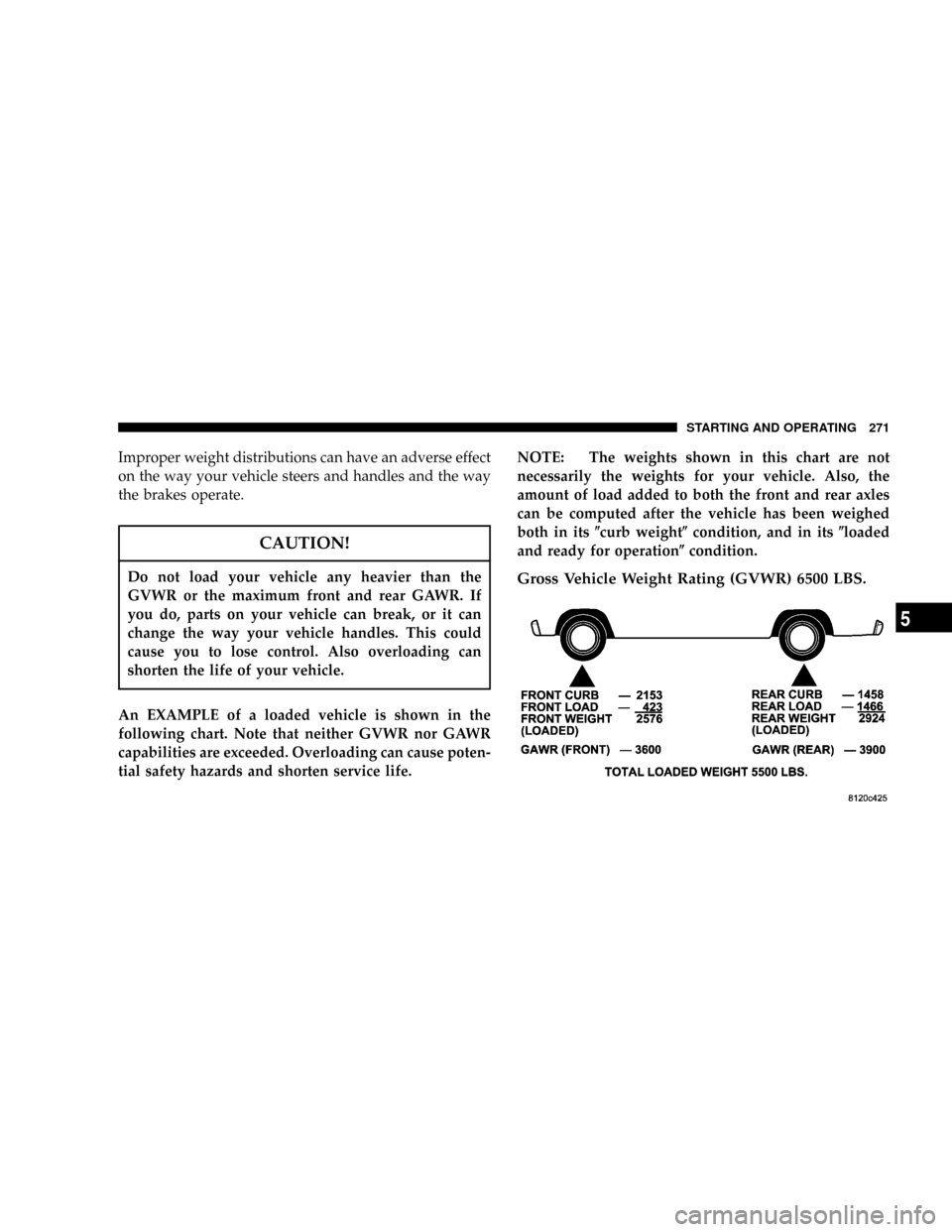
An EXAMPLE of a loaded vehicle is shown in the
following chart. Note that neither GVWR nor GAWR
capabilities are exceeded. Overloading can cause poten-
tial safety hazards and shorten service life.NOTE: The weights shown in this chart are not
necessarily the weights for your vehicle. Also, the
amount of load added to both the front and rear axles
can be computed after the vehicle has been weighed
both in its(curb weight(condition, and in its(loaded
and ready for operation(condition.
Gross Vehicle Weight Rating (GVWR) 6500 LBS.
STARTING AND OPERATING 271
5
Page 281 of 426
²Highway DrivingÐreduce your speed.
²Air ConditioningÐturn it off temporarily.
²Hilly TerrainÐTurn overdrive off.
See Cooling System Operating information in the Service
and Maintenance section of this manual for more infor-
mation.
Automatic Transmission Oil Temperature Warning
Light
All vehicles with heavy duty transmission oil cooling are
equipped with a transmission sump oil temperature
sensor and warning light. If elevated transmission tem-
peratures are encountered, the engine controller will
select the most desirable gear until the transmission
temperatures are reduced. If transmission oil tempera-
tures continue to rise, a warning light located in theinstrument cluster will illuminate. If this should occur,
stop the vehicle, shift to Neutral, and run the engine at
idle or faster until the light goes off.
Towing With An Automatic Transmission
Vehicles equipped with an automatic transmission may
shift into and out of Overdrive, or a lower gear, when
driving in hilly areas, when heavily loaded, or when
towing into heavy winds.
When this condition occurs, press the ªTOW/HAULº
button or shift into a lower gear to prevent excessive
transmission wear and/or overheating, and to provide
better engine braking.
NOTE:Do not exceed the following RPM while manu-
ally downshifting:
²5.9L Diesel Engines 3200 RPM.
STARTING AND OPERATING 281
5
Page 294 of 426
3. Replace tires when tread wear indicators first become
visible.
4. Keep tires properly inflated.
5. Maintain sufficient distance between your vehicle and
the car in front to avoid a collision in a sudden stop.ENGINE DATA PLATE
Use the information from the engine data plate when
discussing service or sourcing parts for your engine. The
engine data plate is located on the intake side of the
breather cover.
294 STARTING AND OPERATING
Page 297 of 426
ADDING FUEL Ð 24±VALVE CUMMINS TURBO
DIESEL
WARNING!
A fire may result if fuel is pumped into a portable
container that is on a truck bed. You could be
burned. Always place fuel containers on the ground
while filling.
NOTE:When a diesel engine is allowed to run out of
fuel, air is pulled into the fuel system.
You may try priming as described below. However, if the
engine will not start, refer to the fuel priming procedure
in the Service Manual or have the vehicle towed to an
authorized Dodge dealer.
WARNING!
Do not open the high pressure fuel system with the
engine running. Engine operation causes high fuel
pressure. High pressure fuel spray can cause serious
injury or death.
Priming if the engine has run out of fuel
1. Add a substantial quantity of fuel to the tank 5 to 10
gallons (19 to 38L).
2. Crank the engine for 1 to 2 seconds. If the engine does
not start, then release the key or starter button back to the
RUN position (do not turn the key back to the OFF
position). The electric fuel transfer pump will continue to
run and purge air from the system for about 25 seconds.
After 25 seconds, attempt to start the engine again.
3. Start the engine using the Normal Starting Procedure.
WHAT TO DO IN EMERGENCIES 297
6
Page 299 of 426
WARNING!
The jack is designed to use as a tool for changing
tires only. The jack should not be used to lift the
vehicle for service purposes, unless suitable sup-
ports are placed under the vehicle as a safety mea-
sure. The vehicle should be jacked on a firm level
surface only. Avoid ice or slippery areas.
WARNING!
After using the jack and tools, always reinstall them
in the original carrier and location. While driving
you may experience, abrupt stopping, rapid accelera-
tion, or sharp turns. A loose jack, tools, bracket or
other objects in the vehicle may move around with
force, resulting in serious injury.
CHANGING A FLAT TIRE
Removing The Spare Tire
Remove the spare tire before attempting to jack the truck.
Attach the wheel wrench to the jack extension tube. Insert
the tube through the access hole between the lower
tailgate and the top of the bumper and into the winch
mechanism tube. Rotate the wheel wrench handle coun-
terclockwise until the spare tire is on the ground with
enough cable slack to allow you to pull it out from under
the vehicle. When the spare is clear, tilt the retainer at the
end of the cable and pull it through the center of the
wheel.
WHAT TO DO IN EMERGENCIES 299
6
Page 300 of 426
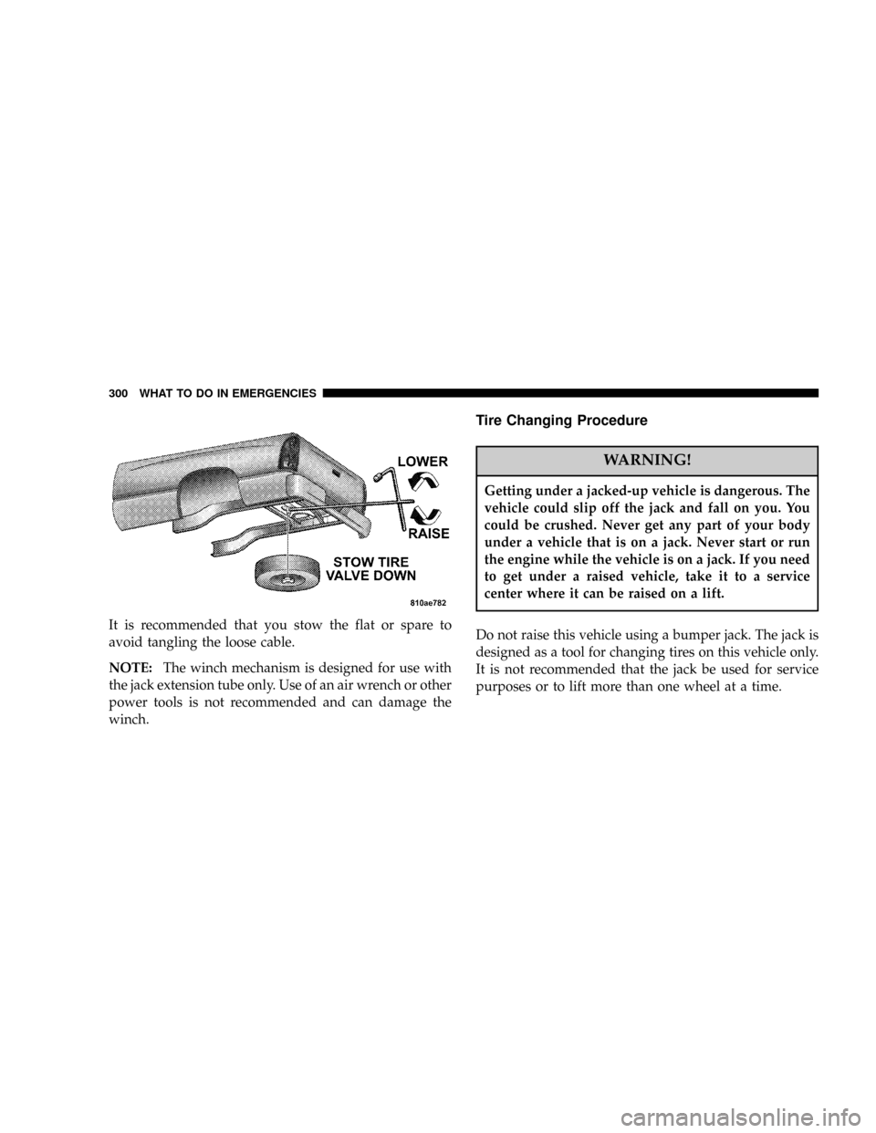
It is recommended that you stow the flat or spare to
avoid tangling the loose cable.
NOTE:The winch mechanism is designed for use with
the jack extension tube only. Use of an air wrench or other
power tools is not recommended and can damage the
winch.
Tire Changing Procedure
WARNING!
Getting under a jacked-up vehicle is dangerous. The
vehicle could slip off the jack and fall on you. You
could be crushed. Never get any part of your body
under a vehicle that is on a jack. Never start or run
the engine while the vehicle is on a jack. If you need
to get under a raised vehicle, take it to a service
center where it can be raised on a lift.
Do not raise this vehicle using a bumper jack. The jack is
designed as a tool for changing tires on this vehicle only.
It is not recommended that the jack be used for service
purposes or to lift more than one wheel at a time.
300 WHAT TO DO IN EMERGENCIES
Page 305 of 426
WARNING!
Raising the vehicle higher than necessary can make
the vehicle unstable and cause an accident. It could
slip off the jack and hurt someone near it. Raise the
vehicle only enough to remove the tire.
5. Remove the wheel nuts and pull the wheel off. Install
the spare wheel and wheel nuts with the cone shaped end
of the nuts toward the wheel on 2500/3500 single rear
wheel (SRW) models. On 3500 dual rear wheel models
(DRW) the lug nuts are a two piece assembly with a flat
face. Lightly tighten the nuts. To avoid risk of forcing the
vehicle off the jack, do not fully tighten the nuts until the
vehicle has been lowered.
6. Using the wheel wrench, finish tightening the nuts
using a crisscross pattern. Correct nut tightness is 135 ft.
lbs. (183 N´m) torque for 2500/3500 single rear wheel(SRW) models and 145 ft. lbs. (197 N´m) for 3500 dual rear
wheel models. If in doubt about the correct tightness,
have them checked with a torque wrench by your dealer
or at a service station.
WARNING!
A loose tire or jack thrown forward in a collision or
hard stop could injure someone in the vehicle.
Always stow the jack parts and the extra tire and
wheel in the places provided.
7. Install wheel center cap and remove wheel blocks. Do
not install chrome or aluminum wheel center caps on the
spare wheel. This may result in cap damage.
8. Lower the jack to its fully closed position. If the jack
will not lower by turning the dial (thumb wheel) by
WHAT TO DO IN EMERGENCIES 305
6
Page 317 of 426
MAINTAINING YOUR VEHICLE
CONTENTS
mEngine Compartment....................320
N5.9L/5.9L HO Cummins Turbo Diesel.......320
mOnboard Diagnostic System (OBD II).........321
mReplacement Parts......................322
mDealer Service.........................322
mService Information.....................322
mMaintenance Procedures..................325
NEngine Oil..........................325
NDrive Belt...........................331NEngine Air Cleaner Filter................331
NDraining Fuel/Water Separator Filter.......334
NMaintenance Free Batteries...............336
NAir Conditioner Maintenance.............338
NPower Steering Ð Fluid Check............339
NFront Suspension Ball Joints..............340
NSteering Linkage Ð Inspection............340
NFront Axle Universal Drive Joints And Pivot
Bearings............................340
7
Page 321 of 426

ONBOARD DIAGNOSTIC SYSTEM (OBD II)
CARB emission control vehicles are equipped with a
sophisticated onboard diagnostic system called OBDII.
This system monitors the performance of the emissions,
engine, and automatic transmission control systems.
When these systems are operating properly, your vehicle
will provide excellent performance and fuel economy, as
well as engine emissions well within current government
regulations.
If any of these systems require service, the OBD II system
will turn on the ªMalfunction Indicator Light.º It will
also store diagnostic codes and other information to
assist your service technician in making repairs. Al-
though your vehicle will usually be driveable and not
need towing, see your dealer for service as soon as
possible.CAUTION!
Prolonged driving with the ªMalfunction Indicator
Lightº on could cause further damage to the emis-
sion control system. It could also affect fuel economy
and driveability. The vehicle must be serviced before
any emissions tests can be performed.
If the ªMalfunction Indicator Lightº is flashing,
severe catalytic converter damage and power loss
will soon occur. Immediate service is required.
MAINTAINING YOUR VEHICLE 321
7