service DODGE RAM 2500 DIESEL 2008 3.G Repair Manual
[x] Cancel search | Manufacturer: DODGE, Model Year: 2008, Model line: RAM 2500 DIESEL, Model: DODGE RAM 2500 DIESEL 2008 3.GPages: 527, PDF Size: 8.88 MB
Page 450 of 527
CAUTION!
Using a transmission fluid other than the manufac-
turers recommended fluid may cause deterioration in
transmission shift quality and/or torque converter
shudder. Using a transmission fluid other than the
manufacturers recommended fluid will result in
more frequent fluid and filter changes. Refer to
Fluids, Lubricants and Genuine Parts for correct
fluid type.
Fluid Level Check
If equipped with a dipstick, use the following procedure.
If your vehicle has a capped dipstick tube, it is sealed and
should not be tampered with. Your authorized dealer has
the proper tools to ensure that the fluid level is set
properly. The fluid level should be checked when theengine is fully warmed up and the fluid in the transmis-
sion is at normal operating temperature. Operation of the
transmission with an improper fluid level will greatly
reduce the life of the transmission and of the fluid. Check
the fluid level whenever the vehicle is serviced.
Procedure For Checking Fluid Level
To properly check the automatic transmission fluid level,
the following procedure must be used:
1. Operate the engine at idle speed and normal operating
temperature.
2. The vehicle must be on level ground.
3. Fully apply the parking brake and press the brake
pedal.
4. Place the gear selector momentarily in each gear
position ending with the lever in PARK.
448 MAINTAINING YOUR VEHICLE
Page 452 of 527
Automatic Transmission Fluid and Filter Change
To obtain best performance and long life for automatic
transmissions, the manufacturer recommends that they
be given regular maintenance service by an authorized
dealer or Service Center. It is important that the trans-
mission fluid is maintained at the correct level, and that
it is drained and refilled as specified.
Use only manufacturer 's recommended transmission
fluid; for correct fluid type, refer to ªAutomatic Trans-
missionº under ªFluids, Lubricants and Genuine Partsº
in this section. It is important that the transmission fluid
be maintained at the prescribed level using the recom-
mended fluid..
The fluid and filter(s) should be changed as specified in
the Maintenance Schedule (Section 8).
NOTE:If the transmission is disassembled for any
reason, the fluid and filter should be changed.
Special Additives
Automatic Transmission Fluid (ATF) is an engineered
product and its performance may be impaired by supple-
mental additives. Therefore, do not add any fluid addi-
tives to the transmission. The only exception to this
policy is the use of special dyes to aid in detecting fluid
leaks. In addition, avoid using transmission sealers as
they may adversely affect seals.
Front Wheel Bearings
Front wheel bearings for your vehicle are sealed-for-life.
They do not require greasing or seal replacement. In
some instances, these bearings will ªpurgeº excess grease
and the bearing housing will look slightly wet. This is
normal.
²Periodic inspection for excess play is recommended.
²If a bearing assembly is accidentally separated when
servicing the brake rotors, it should be replaced.
450 MAINTAINING YOUR VEHICLE
Page 454 of 527
Required Maintenance For Noise Control Systems
The following maintenance services must be performed
every 6 months or 6,000 miles (9 600 km), whichever
comes first, to assure proper operation of the noise
control systems. In addition, inspection and service
should be performed anytime a malfunction is observed
or suspected. Proper maintenance of the entire vehicle
will help the effectiveness of the noise control systems.
Exhaust System
Inspect the entire exhaust system for leaks and damaged
parts. Devices such as hangers, clamps, and U-bolts
should be tight and in good condition. Damaged compo-
nents, burned or blown out mufflers, burned or rusted
out exhaust pipes should be replaced according to the
procedures and specifications outlined in the appropriate
service manual.Air Cleaner Assembly
Inspect air cleaner housing for proper assembly and fit.
Make certain that the air cleaner is properly positioned
and that the cover is tight. Check all hoses leading to the
air cleaner for tightness. The air filter element must also
be clean and serviced according to the instructions out-
lined in the Maintenance Schedule Section of this
manual.
Tampering With Noise Control System Prohibited
Federal law prohibits the following acts or the causing
thereof: (1) the removal or rendering inoperative by any
person, other than for purposes of maintenance, repair, or
replacement, of any device or element of design incorpo-
rated into any new vehicle for the purpose of noise
control prior to its sale or delivery to the ultimate
purchaser or while it is in use, or (2) the use of the vehicle
after such device or element of design has been removed
or rendered inoperative by any person.
452 MAINTAINING YOUR VEHICLE
Page 456 of 527
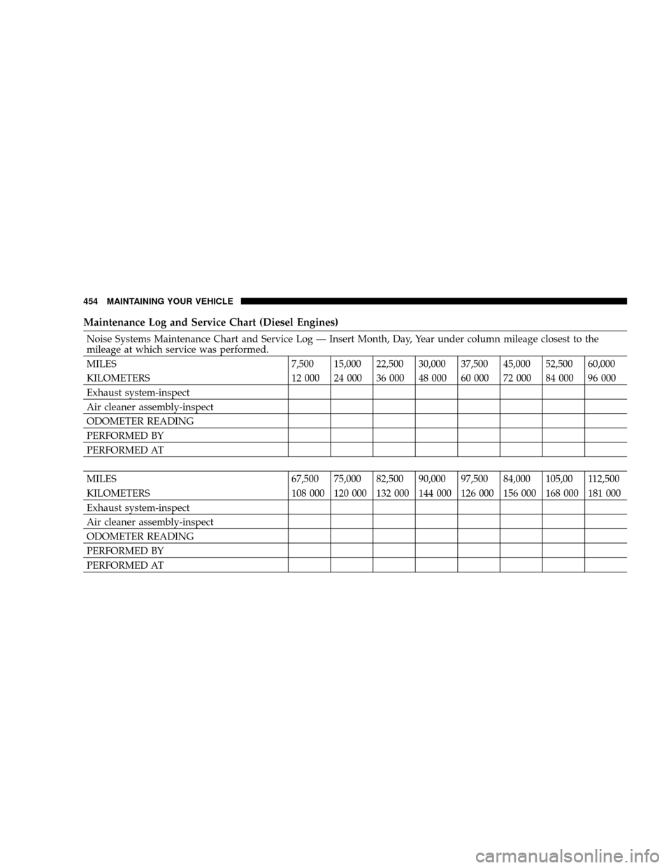
Maintenance Log and Service Chart (Diesel Engines)
Noise Systems Maintenance Chart and Service Log Ð Insert Month, Day, Year under column mileage closest to the
mileage at which service was performed.
MILES 7,500 15,000 22,500 30,000 37,500 45,000 52,500 60,000
KILOMETERS 12 000 24 000 36 000 48 000 60 000 72 000 84 000 96 000
Exhaust system-inspect
Air cleaner assembly-inspect
ODOMETER READING
PERFORMED BY
PERFORMED AT
MILES 67,500 75,000 82,500 90,000 97,500 84,000 105,00 112,500
KILOMETERS 108 000 120 000 132 000 144 000 126 000 156 000 168 000 181 000
Exhaust system-inspect
Air cleaner assembly-inspect
ODOMETER READING
PERFORMED BY
PERFORMED AT
454 MAINTAINING YOUR VEHICLE
Page 466 of 527
VEHICLE STORAGE
If you are storing your vehicle for more than 21 days, we
recommend that you take the following steps to mini-
mize the drain on your vehicle's battery:
²Disconnect the Ignition-Off Draw fuse (IOD) fuse
located in the Integrated Power Module, located in the
engine compartment. The IOD cavity includes a
snap-in retainer that allows the fuse to be discon-
nected, without removing it from the fuse block.
²The electronic shift transfer case should be placed in
the 4HI mode and kept in this position to minimize the
battery drain.
²As an alternative to the above steps you may discon-
nect the negative cables from both batteries.
²Any time you store your vehicle, or keep it out of
service (i.e., vacation) for two weeks or more, run the
air conditioning system at idle for about five minutesin the fresh air and high blower setting. This will
ensure adequate system lubrication to minimize the
possibility of compressor damage when the system is
started again.
NOTE:When reinstalling the IOD fuse push firmly until
fully seated; the gauges in the instrument cluster will do
a full sweep when the ignition key is cycled to RUN. This
is a normal condition.
NOTE:When the vehicle is shipped from the factory,
the IOD fuse is in the up, or extracted position. If the
radio, interior lamps, keyless entry, or other features do
not work with the key OFF, check the position of the fuse
(or check to see if the fuse is blown) to ensure that it is
fully seated. When the IOD fuse is extracted, the instru-
ment cluster in the odometer window will display9NO
FUSE.º
464 MAINTAINING YOUR VEHICLE
Page 483 of 527
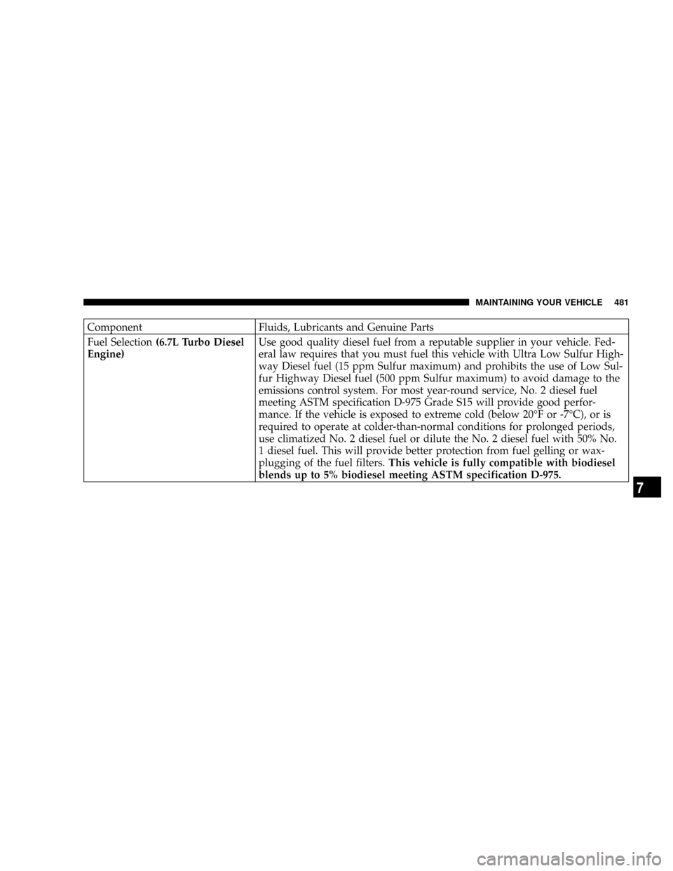
Component Fluids, Lubricants and Genuine Parts
Fuel Selection(6.7L Turbo Diesel
Engine)Use good quality diesel fuel from a reputable supplier in your vehicle. Fed-
eral law requires that you must fuel this vehicle with Ultra Low Sulfur High-
way Diesel fuel (15 ppm Sulfur maximum) and prohibits the use of Low Sul-
fur Highway Diesel fuel (500 ppm Sulfur maximum) to avoid damage to the
emissions control system. For most year-round service, No. 2 diesel fuel
meeting ASTM specification D-975 Grade S15 will provide good perfor-
mance. If the vehicle is exposed to extreme cold (below 20ÉF or -7ÉC), or is
required to operate at colder-than-normal conditions for prolonged periods,
use climatized No. 2 diesel fuel or dilute the No. 2 diesel fuel with 50% No.
1 diesel fuel. This will provide better protection from fuel gelling or wax-
plugging of the fuel filters.This vehicle is fully compatible with biodiesel
blends up to 5% biodiesel meeting ASTM specification D-975.
MAINTAINING YOUR VEHICLE 481
7
Page 485 of 527
MAINTENANCE SCHEDULES
CONTENTS
mEmission Control System Maintenance........484
mMaintenance Schedules Ð 6.7L Turbo Diesel....484
NOil Change Indicator System.............486NPerform Service Indicator...............486
NMaintenance Schedule..................487
8
M
A
I
N
T
E
N
A
N
C
E
S
C
H
E
D
U
L
E
S
Page 486 of 527
EMISSION CONTROL SYSTEM MAINTENANCE
The Scheduled maintenance services, listed inbold type
in this section (Section 8) must be done at the times or
mileages specified to assure the continued proper func-
tioning of the emission control system. These, and all
other maintenance services included in this manual,
should be done to provide best vehicle performance and
reliability. More frequent maintenance may be needed for
vehicles in severe operating conditions, such as dusty
areas and very short trip driving.
Inspection and service also should be done anytime a
malfunction is suspected.
NOTE:Maintenance, replacement, or repair of the emis-
sion control devices and systems on your vehicle may be
performed by any automotive repair establishment or
individual using any automotive part which has been
certified pursuant to U.S. EPA or, in the State of Califor-
nia, California Air Resources Board regulations.
MAINTENANCE SCHEDULES Ð 6.7L TURBO
DIESEL
CAUTION!
Failure to perform the required maintenance items
may result in damage to the vehicle.
At Each Stop for Fuel
²Check the engine oil level about 30 minutes after a
fully warmed engine is shut off. Checking the oil level
while the vehicle is on level ground will improve the
accuracy of the oil level reading. Add oil only when
the level is at or below the ADD or MIN mark.
²Check the windshield washer solvent and add if
required. When refilling the washer fluid reservoir,
484 MAINTENANCE SCHEDULES
8
M
A
I
N
T
E
N
A
N
C
E
S
C
H
E
D
U
L
E
S
Page 487 of 527
take some washer fluid and apply it to a cloth or towel
and wipe clean the wiper blades, this will help blade
performance.
Once a Month
²Check tire pressure and look for unusual wear or
damage.
²Inspect the batteries and clean and tighten the termi-
nals as required.
²Check the fluid levels of coolant reservoir, brake
master cylinder, and transmission and transfer case (if
equipped), add as needed.
²Check all lights and all other electrical items for correct
operation.
²Drain water from the fuel filter.
²Check Filter MinderŸ (If Equipped). Replace air
cleaner filter element if necessary.At Each Oil Change
²Change the engine oil filter.
²Inspect the exhaust system.
²Inspect the brake hoses.
²Inspect the U-Joints (if equipped) and front suspension
components.
²Check the automatic transmission fluid level.
²Check the manual transmission fluid level.
²Check the coolant level, hoses, and clamps.
²Lubricate outer tie rod ends (4X4) models only.
²Lubricate Front Drive Shaft Fitting (4X4).
Inspection and service should also be performed anytime
a malfunction is observed or suspected. Retain all re-
ceipts.
MAINTENANCE SCHEDULES 485
8
M
A
I
N
T
E
N
A
N
C
E
S
C
H
E
D
U
L
E
S
Page 488 of 527
Oil Change Indicator System
Your vehicle is equipped with an engine oil change
indicator system. This system will alert you when it is
time to change your engine oil by displaying the words
ªOil Change Requiredº on your Electronic Vehicle Infor-
mation Center (EVIC). The engine oil change indicator
system is duty cycle based, which means the engine oil
change interval may fluctuate depending on your per-
sonal driving style. Driving styles such as frequent stop
and go type driving can increase the frequency of the
engine oil change. This is the result of more frequent
regeneration of the exhaust aftertreatment system, which
can decrease the life of the engine oil. Failure to change
the engine oil per the maintenance schedule can result in
internal engine damage.
For information on resetting the Oil Change Indicator
message, refer to ªOil Change Required ± If Equipped,ºunder ªSystem Status (EVIC Displays)º in the ªElectronic
Vehicle Information Center (EVIC)º Section of this
manual.
Perform Service Indicator
Your vehicle will require emissions maintenance at a set
interval. To help remind you when this maintenance is
due, the Electronic Vehicle Information Center (EVIC)
will display ªPerform Serviceº. When the ªPerform Ser-
viceº message is displayed on the EVIC it is necessary to
have the emissions maintenance performed. Emissions
maintenance includes replacing the Closed Crankcase
Ventilation (CCV) filter element, cleaning of the EGR
Cooler, and cleaning of the EGR Valve. The procedure for
clearing and resetting the9Perform Service9indicator
message is located in the appropriate Service Informa-
tion.
486 MAINTENANCE SCHEDULES
8
M
A
I
N
T
E
N
A
N
C
E
S
C
H
E
D
U
L
E
S