check engine DODGE RAM SRT-10 2006 Service Repair Manual
[x] Cancel search | Manufacturer: DODGE, Model Year: 2006, Model line: RAM SRT-10, Model: DODGE RAM SRT-10 2006Pages: 5267, PDF Size: 68.7 MB
Page 3811 of 5267
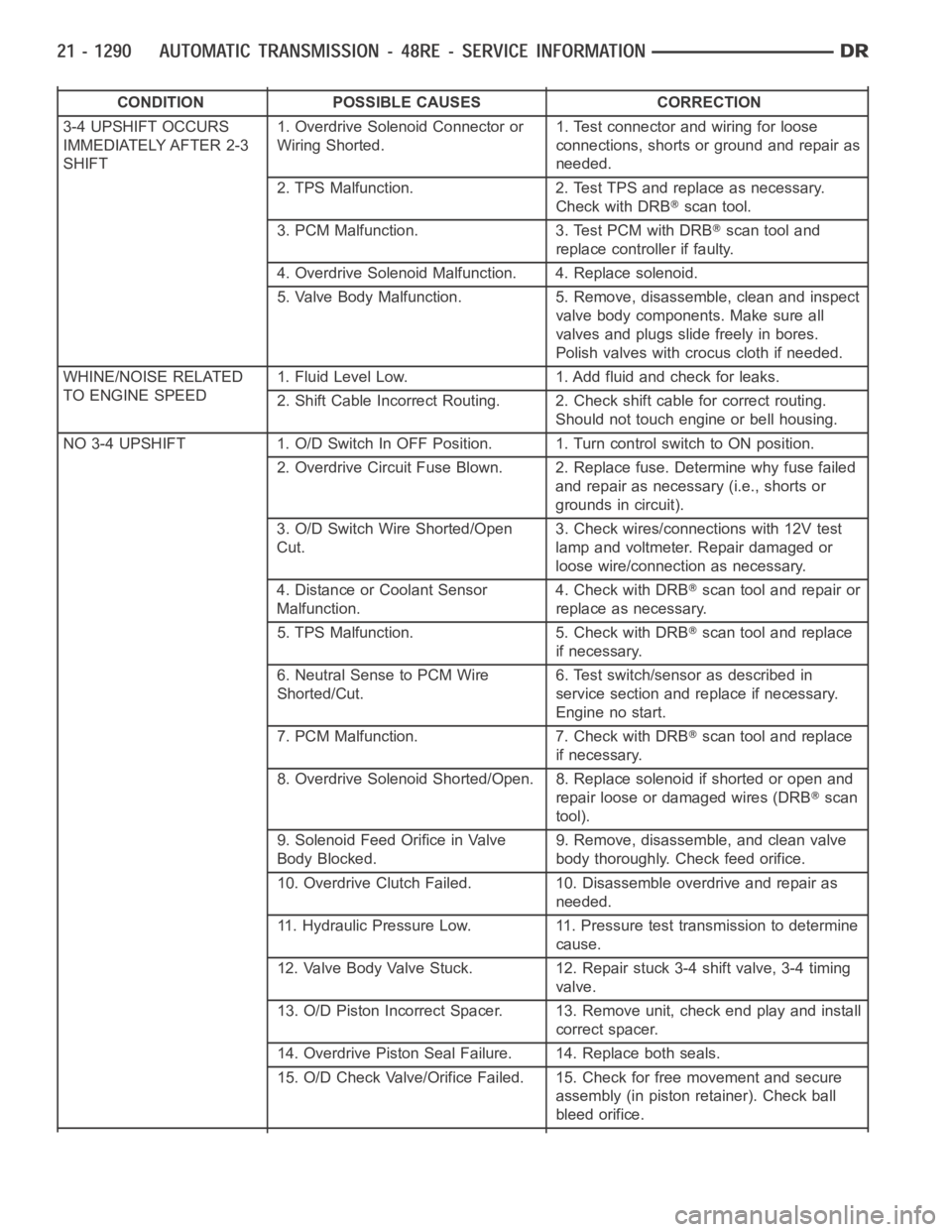
CONDITION POSSIBLE CAUSES CORRECTION
3-4 UPSHIFT OCCURS
IMMEDIATELY AFTER 2-3
SHIFT1. Overdrive Solenoid Connector or
Wiring Shorted.1. Test connector and wiring for loose
connections, shorts or ground and repair as
needed.
2. TPS Malfunction. 2. Test TPS and replace as necessary.
Check with DRB
scan tool.
3. PCM Malfunction. 3. Test PCM with DRB
scan tool and
replace controller if faulty.
4. Overdrive Solenoid Malfunction. 4. Replace solenoid.
5. Valve Body Malfunction. 5. Remove, disassemble, clean and inspect
valve body components. Make sure all
valves and plugs slide freely in bores.
Polish valves with crocus cloth if needed.
WHINE/NOISE RELATED
TO ENGINE SPEED1. Fluid Level Low. 1. Add fluid and check for leaks.
2. Shift Cable Incorrect Routing. 2. Check shift cable for correct routing.
Should not touch engine or bell housing.
NO3-4UPSHIFT 1.O/DSwitchInOFFPosition. 1.TurncontrolswitchtoONposition.
2. Overdrive Circuit Fuse Blown. 2. Replace fuse. Determine why fuse failed
and repair as necessary (i.e., shorts or
grounds in circuit).
3. O/D Switch Wire Shorted/Open
Cut.3. Check wires/connections with 12V test
lamp and voltmeter. Repair damaged or
loose wire/connection as necessary.
4. Distance or Coolant Sensor
Malfunction.4. Check with DRB
scan tool and repair or
replace as necessary.
5. TPS Malfunction. 5. Check with DRB
scan tool and replace
if necessary.
6. Neutral Sense to PCM Wire
Shorted/Cut.6. Test switch/sensor as described in
service section and replace if necessary.
Engine no start.
7. PCM Malfunction. 7. Check with DRB
scan tool and replace
if necessary.
8. Overdrive Solenoid Shorted/Open. 8. Replace solenoid if shorted or openand
repair loose or damaged wires (DRB
scan
tool).
9. Solenoid Feed Orifice in Valve
Body Blocked.9. Remove, disassemble, and clean valve
body thoroughly. Check feed orifice.
10. Overdrive Clutch Failed. 10. Disassemble overdrive and repair as
needed.
11. Hydraulic Pressure Low. 11. Pressure test transmission to determine
cause.
12. Valve Body Valve Stuck. 12. Repair stuck 3-4 shift valve, 3-4 timing
valve.
13. O/D Piston Incorrect Spacer. 13. Remove unit, check end play and install
correct spacer.
14. Overdrive Piston Seal Failure. 14. Replace both seals.
15. O/D Check Valve/Orifice Failed. 15. Check for free movement and secure
assembly (in piston retainer). Check ball
bleed orifice.
Page 3838 of 5267
INSTALLATION
1. Check torque converter hub inner and outer diam-
eters and hub drive notches for sharp edges burrs,
scratches, or nicks. Polish the hub and notches
with 320/400 grit paper and crocus cloth if neces-
sary. The hub must be smooth to avoid damaging
pump seal at installation.
2. Lubricate pocket in the rear oil pump seal lip with
transmission fluid.
3. Lubricate converter pilot hub of the crankshaft with
a light coating of Mopar
High Temp Grease.
4. Align and install converter in oil pump.
5. Carefully insert converter in oil pump. Then rotate
converter back and forth until fully seated in pump
gears.
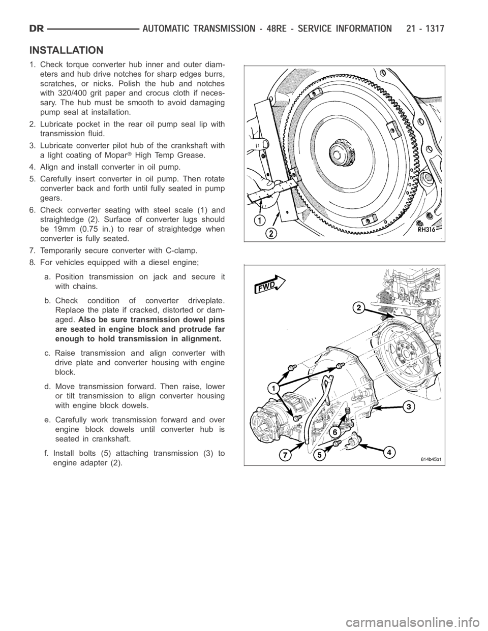
6. Check converter seating with steel scale (1) and
straightedge (2). Surface of converter lugs should
be 19mm (0.75 in.) to rear of straightedge when
converter is fully seated.
7. Temporarily secure converter with C-clamp.
8. For vehicles equipped with a diesel engine;
a. Position transmission on jack and secure it
with chains.
b. Check condition of converter driveplate.
Replace the plate if cracked, distorted or dam-
aged.Also be sure transmission dowel pins
are seated in engine block and protrude far
enough to hold transmission in alignment.
c. Raise transmission and align converter with
drive plate and converter housing with engine
block.
d. Move transmission forward. Then raise, lower
or tilt transmission to align converter housing
with engine block dowels.
e. Carefully work transmission forward and over
engine block dowels until converter hub is
seated in crankshaft.
f. Install bolts (5) attaching transmission (3) to
engine adapter (2).
Page 3839 of 5267
9. For vehicles equipped with a gas engine;
a. Position transmission on jack and secure it
with chains.
b. Check condition of converter driveplate.
Replace the plate if cracked, distorted or dam-
aged.Also be sure transmission dowel pins
are seated in engine block and protrude far
enough to hold transmission in alignment.
c. Raise transmission and align converter with
drive plate and converter housing with engine
block.
d. Move transmission forward. Then raise, lower
or tilt transmission to align converter housing
with engine block dowels.
e. Carefully work transmission forward and over
engine block dowels until converter hub is
seated in crankshaft.
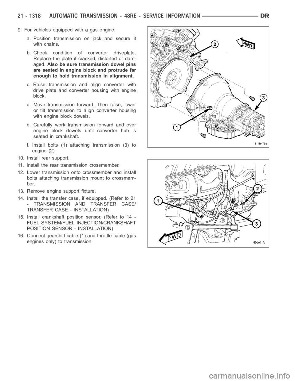
f. Install bolts (1) attaching transmission (3) to
engine (2).
10. Install rear support.
11. Install the rear transmission crossmember.
12. Lower transmission onto crossmember and install
bolts attaching transmission mount to crossmem-
ber.
13. Remove engine support fixture.
14. Install the transfer case, if equipped. (Refer to 21
- TRANSMISSION AND TRANSFER CASE/
TRANSFER CASE - INSTALLATION)
15. Install crankshaft position sensor. (Refer to 14 -
FUEL SYSTEM/FUEL INJECTION/CRANKSHAFT
POSITION SENSOR - INSTALLATION)
16. Connect gearshift cable (1) and throttle cable (gas
engines only) to transmission.
Page 3867 of 5267
ADJUSTMENT PROCEDURE
1. Remove the steering column trim as necessary for
access to the brake transmission shift interlock.
2. Shift the transmission into the PARK position.
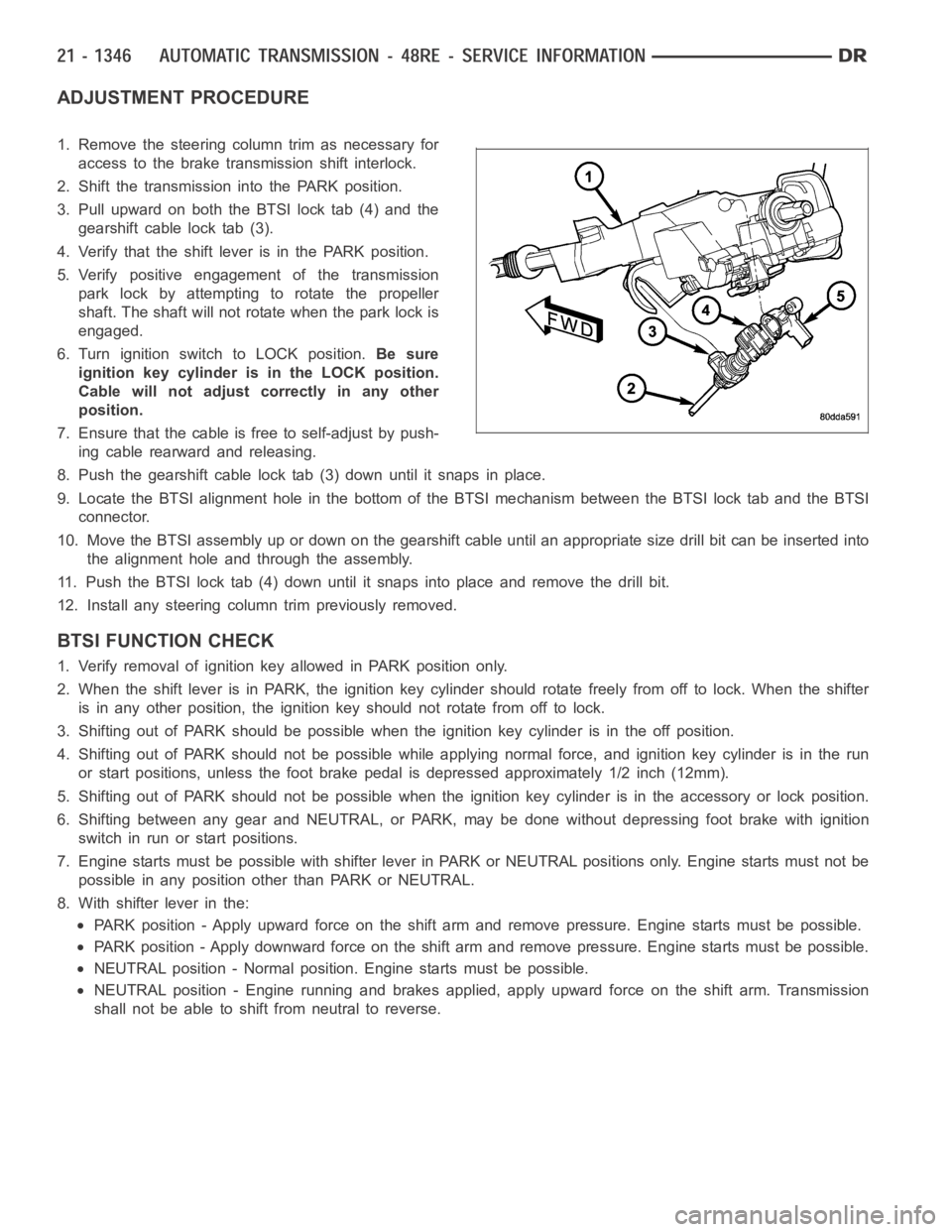
3. Pull upward on both the BTSI lock tab (4) and the
gearshift cable lock tab (3).
4. Verify that the shift lever is in the PARK position.
5. Verify positive engagement of the transmission
park lock by attempting to rotate the propeller
shaft. The shaft will not rotate when the park lock is
engaged.
6. Turn ignition switch to LOCK position.Be sure
ignition key cylinder is in the LOCK position.
Cable will not adjust correctly in any other
position.
7. Ensure that the cable is free to self-adjust by push-
ing cable rearward and releasing.
8. Push the gearshift cable lock tab (3) down until it snaps in place.
9. Locate the BTSI alignment hole in the bottom of the BTSI mechanism betweentheBTSIlocktabandtheBTSI
connector.
10. Move the BTSI assembly up or down on the gearshift cable until an appropriate size drill bit can be inserted into
the alignment hole and through the assembly.
11. Push the BTSI lock tab (4) down until it snaps into place and remove the drill bit.
12. Install any steering column trim previously removed.
BTSI FUNCTION CHECK
1. Verify removal of ignition key allowed in PARK position only.
2. When the shift lever is in PARK, the ignition key cylinder should rotate freely from off to lock. When the shifter
is in any other position, the ignition key should not rotate from off to lock.
3. Shifting out of PARK should be possible when the ignition key cylinder isin the off position.
4. Shifting out of PARK should not be possible while applying normal force,and ignition key cylinder is in the run
or start positions, unless the foot brake pedal is depressed approximately1/2inch(12mm).
5. Shifting out of PARK should not be possible when the ignition key cylinder is in the accessory or lock position.
6. Shifting between any gear and NEUTRAL, or PARK, may be done without depressing foot brake with ignition
switch in run or start positions.
7. Engine starts must be possible with shifter lever in PARK or NEUTRAL positions only. Engine starts must not be
possible in any position other than PARK or NEUTRAL.
8. With shifter lever in the:
PARK position - Apply upward force on the shift arm and remove pressure. Enginestartsmustbepossible.
PARK position - Apply downward force on the shift arm and remove pressure. Engine starts must be possible.
NEUTRAL position - Normal position. Engine starts must be possible.
NEUTRAL position - Engine running and brakes applied, apply upward force on the shift arm. Transmission
shall not be able to shift from neutral to reverse.
Page 3874 of 5267
FLUID AND FILTER
DIAGNOSIS AND TESTING
EFFECTS OF INCORRECT FLUID LEVEL
Alowfluidlevelallowsthepumptotakeinairalongwiththefluid.Airinthe fluid will cause fluid pressures to be
low and develop slower than normal. If the transmission is overfilled, thegears churn the fluid into foam. This aer-
ates the fluid and causing the same conditions occurring with a low level. In either case, air bubbles cause fluid
overheating, oxidation, and varnish buildup which interferes with valveand clutch operation. Foaming also causes
fluid expansion which can result in fluid overflow from the transmission vent or fill tube. Fluid overflow can easily be
mistaken for a leak if inspection is not careful.
CAUSES OF BURNT FLUID
Burnt, discolored fluid is a result of overheating which has two primary causes.
1. A result of restricted fluid flow through the main and/or auxiliary cooler. This condition is usually the result of a
faulty or improperly installed drainback valve, a damaged oil cooler, or severe restrictions in the coolers and lines
caused by debris or kinked lines.
2. Heavy duty operation with a vehicle not properly equipped for this type of operation. Trailer towing or similar high
load operation will overheat the transmission fluid if the vehicle is improperly equipped. Such vehicles should
have an auxiliary transmission fluid cooler, a heavy duty cooling system,and the engine/axle ratio combination
needed to handle heavy loads.
FLUID CONTAMINATION
Transmission fluid contamination is generally a result of:
adding incorrect fluid
failure to clean dipstick and fill tube when checking level
engine coolant entering the fluid
internal failure that generates debris
overheat that generates sludge (fluid breakdown)
failure to replace contaminated converter after repair
The use of non-recommended fluids can result in transmission failure. Theusual results are erratic shifts, slippage,
abnormal wear and eventual failure due to fluid breakdown and sludge formation. Avoid this condition by using rec-
ommended fluids only.
The dipstick cap and fill tube should be wiped clean before checking fluid level. Dirt, grease and other foreign mate-
rial on the cap and tube could fall into the tube if not removed beforehand. Take the time to wipe the cap and tube
clean before withdrawing the dipstick.
Engine coolant in the transmission fluid is generally caused by a cooler malfunction. The only remedy is to replace
the radiator as the cooler in the radiator is not a serviceable part. If coolant has circulated through the transmission,
an overhaul is necessary.
The torque converter should also be replaced whenever a failure generatessludge and debris. This is necessary
because normal converter flushing procedures will not remove all contaminants.
STANDARD PROCEDURE
FLUID LEVEL CHECK
Low fluid level can cause a variety of conditions because it allows the pumpto take in air along with the fluid. As
in any hydraulic system, air bubbles make the fluid spongy, therefore, pressures will be low and build up slowly.
Improper filling can also raise the fluid level too high. When the transmssion has too much fluid, the geartrain
churns up foam and cause the same conditions which occur with a low fluid level.
In either case, air bubbles can cause overheating and/or fluid oxidation,and varnishing. This can interfere with nor-
mal valve, clutch, and accumulator operation. Foaming can also result in fluid escaping from the transmission vent
where it may be mistaken for a leak.
Page 3875 of 5267
After the fluid has been checked, seat the dipstick fully to seal out water and dirt.
The transmission has a dipstick to check oil level. It is located on the right side of the engine. Be sure to wipe all
dirt from dipstick handle before removing.
Fluid level is checked with the engine running at curb idle speed, the transmissioninNEUTRALandthetransmis-
sion fluid at normal operating temperature.The engine should be running at idle speed for at least one minute,
with the vehicle on level ground.
The transmission fluid level can be checked two ways.
PROCEDURE ONE
1. Transmission fluid must be at normal operating
temperature for accurate fluid level check. Drive
vehicle if necessary to bring fluid temperature up to
normal hot operating temperature of 82°C (180°F).
2. Position vehicle on level surface.
3. Start and run engine at curb idle speed.
4. Apply parking brakes.
5. Shift transmission momentarily into all gear ranges.
Then shift transmission back to NEUTRAL.
6. Clean top of filler tube and dipstick to keep dirt from entering tube.
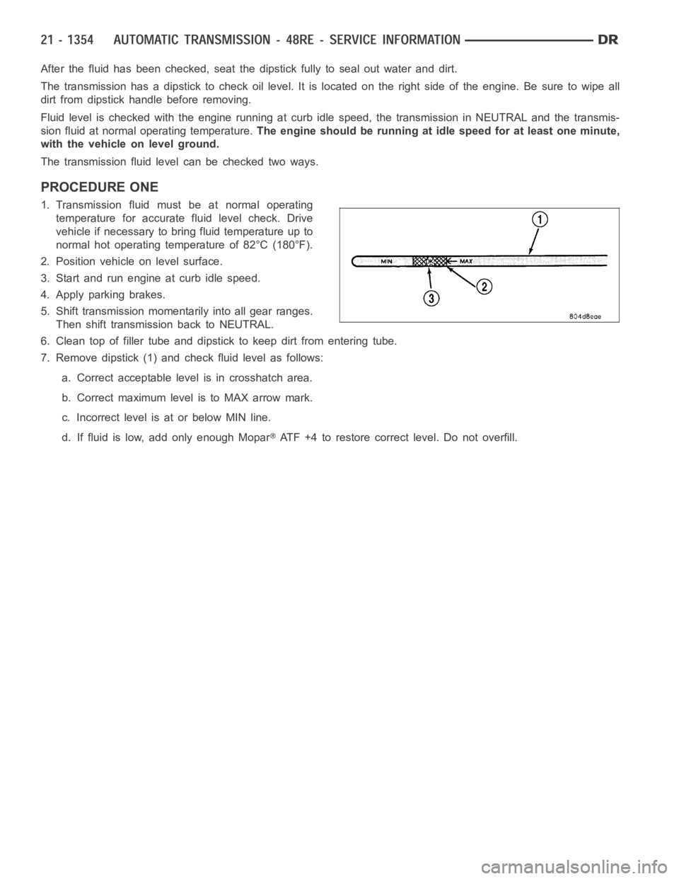
7. Remove dipstick (1) and check fluid level as follows:
a. Correct acceptable level is in crosshatch area.
b. Correct maximum level is to MAX arrow mark.
c. Incorrect level is at or below MIN line.
d. If fluid is low, add only enough Mopar
ATF +4 to restore correct level. Do not overfill.
Page 3876 of 5267
PROCEDURE TWO
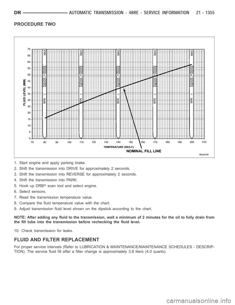
1. Start engine and apply parking brake.
2. Shift the transmission into DRIVE for approximately 2 seconds.
3. Shift the transmission into REVERSE for approximately 2 seconds.
4. Shift the transmission into PARK.
5. Hook up DRB
scan tool and select engine.
6. Select sensors.
7. Read the transmission temperature value.
8. Compare the fluid temperature value with the chart.
9. Adjust transmission fluid level shown on the dipstick according to the chart.
NOTE: After adding any fluid to the transmission, wait a minimum of 2 minutes for the oil to fully drain from
the fill tube into the transmission before rechecking the fluid level.
10. Check transmission for leaks.
FLUID AND FILTER REPLACEMENT
For proper service intervals (Refer to LUBRICATION & MAINTENANCE/MAINTENANCE SCHEDULES - DESCRIP-
TION). The service fluid fill after a filter change is approximately 3.8 liters (4.0 quarts).
Page 3878 of 5267
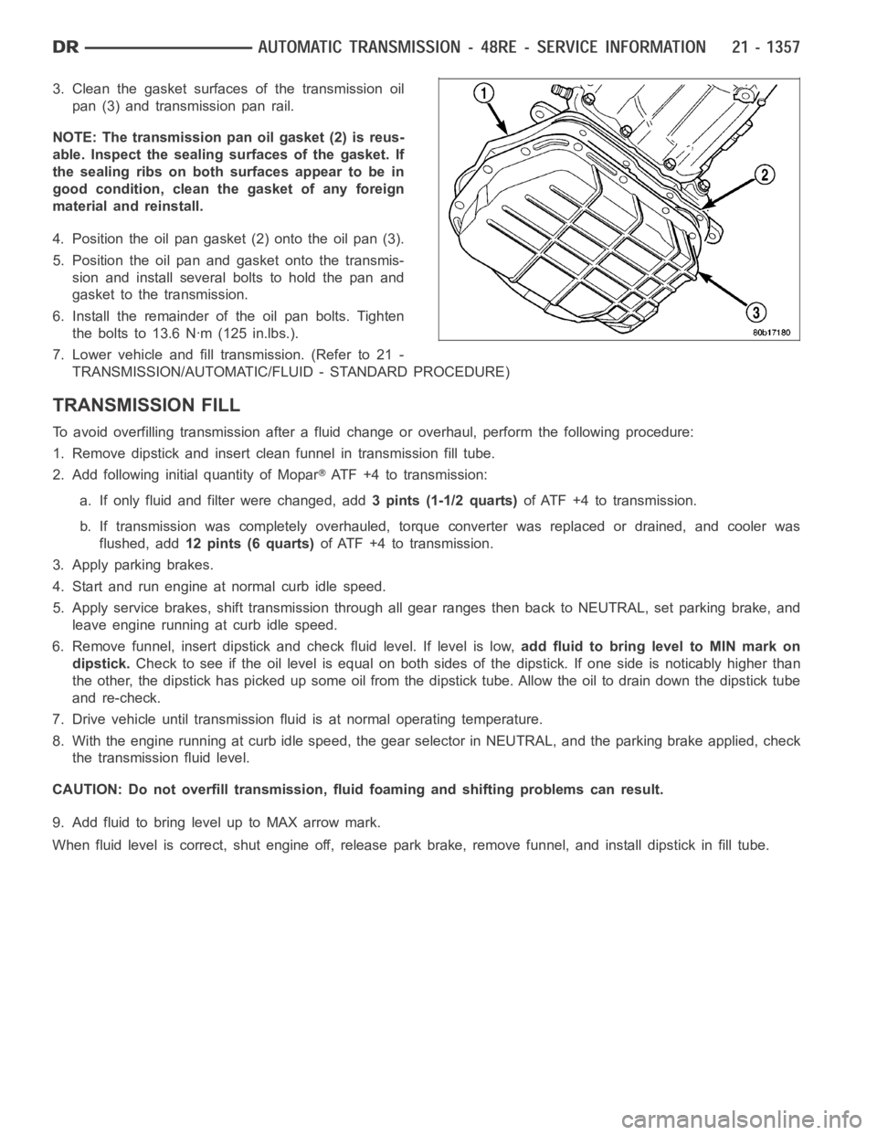
3. Clean the gasket surfaces of the transmission oil
pan (3) and transmission pan rail.
NOTE: The transmission pan oil gasket (2) is reus-
able. Inspect the sealing surfaces of the gasket. If
the sealing ribs on both surfaces appear to be in
good condition, clean the gasket of any foreign
material and reinstall.
4. Position the oil pan gasket (2) onto the oil pan (3).
5. Position the oil pan and gasket onto the transmis-
sion and install several bolts to hold the pan and
gasket to the transmission.
6. Install the remainder of the oil pan bolts. Tighten
the bolts to 13.6 Nꞏm (125 in.lbs.).
7. Lower vehicle and fill transmission. (Refer to 21 -
TRANSMISSION/AUTOMATIC/FLUID - STANDARD PROCEDURE)
TRANSMISSION FILL
To avoid overfilling transmission after a fluid change or overhaul, perform the following procedure:
1. Remove dipstick and insert clean funnel in transmission fill tube.
2. Add following initial quantity of Mopar
ATF+4totransmission:
a. If only fluid and filter were changed, add3 pints (1-1/2 quarts)of ATF +4 to transmission.
b. If transmission was completely overhauled, torque converter was replaced or drained, and cooler was
flushed, add12 pints (6 quarts)of ATF +4 to transmission.
3. Apply parking brakes.
4. Start and run engine at normal curb idle speed.
5. Apply service brakes, shift transmission through all gear ranges then back to NEUTRAL, set parking brake, and
leave engine running at curb idle speed.
6. Remove funnel, insert dipstick andcheck fluid level. If level is low,add fluid to bring level to MIN mark on
dipstick.Check to see if the oil level is equal on both sides of the dipstick. If one side is noticably higher than
the other, the dipstick has picked up some oil from the dipstick tube. Allowthe oil to drain down the dipstick tube
and re-check.
7. Drive vehicle until transmission fluid is at normal operating temperature.
8. With the engine running at curb idle speed, the gear selector in NEUTRAL,and the parking brake applied, check
the transmission fluid level.
CAUTION: Do not overfill transmission, fluid foaming and shifting problems can result.
9. Add fluid to bring level up to MAX arrow mark.
When fluid level is correct, shut engine off, release park brake, remove funnel, and install dipstick in fill tube.
Page 3889 of 5267
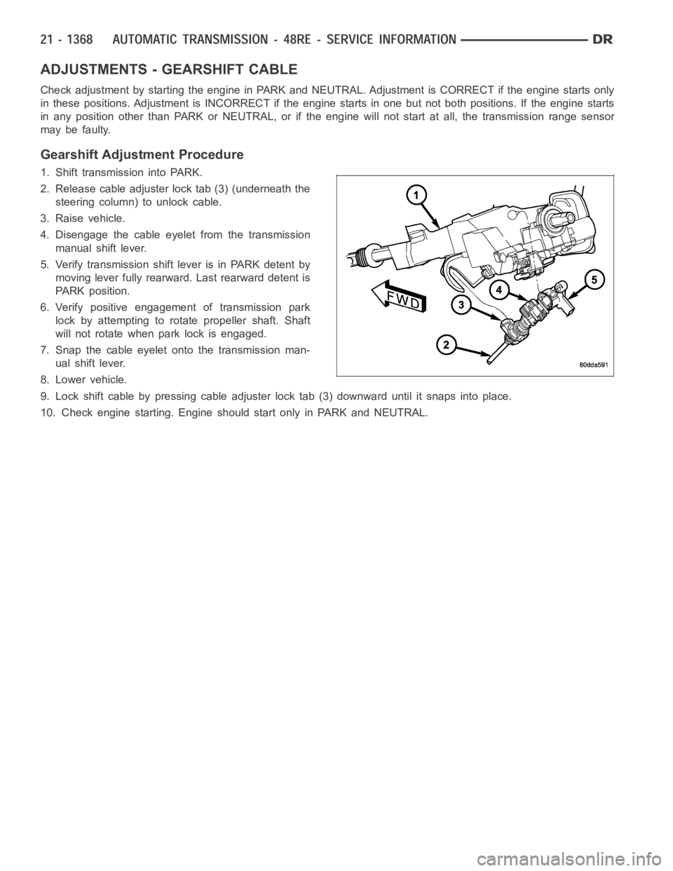
ADJUSTMENTS - GEARSHIFT CABLE
Check adjustment by starting the engine in PARK and NEUTRAL. Adjustment isCORRECT if the engine starts only
in these positions. Adjustment is INCORRECT if the engine starts in one butnot both positions. If the engine starts
in any position other than PARK or NEUTRAL, or if the engine will not start atall, the transmission range sensor
may be faulty.
Gearshift Adjustment Procedure
1. Shift transmission into PARK.
2. Release cable adjuster lock tab (3) (underneath the
steering column) to unlock cable.
3. Raise vehicle.
4. Disengage the cable eyelet from the transmission
manual shift lever.
5. Verify transmission shift lever is in PARK detent by
moving lever fully rearward. Last rearward detent is
PARK position.
6. Verify positive engagement of transmission park
lock by attempting to rotate propeller shaft. Shaft
will not rotate when park lock is engaged.
7. Snap the cable eyelet onto the transmission man-
ual shift lever.
8. Lower vehicle.
9. Lock shift cable by pressing cable adjuster lock tab (3) downward until it snaps into place.
10. Check engine starting. Engine should start only in PARK and NEUTRAL.
Page 3937 of 5267
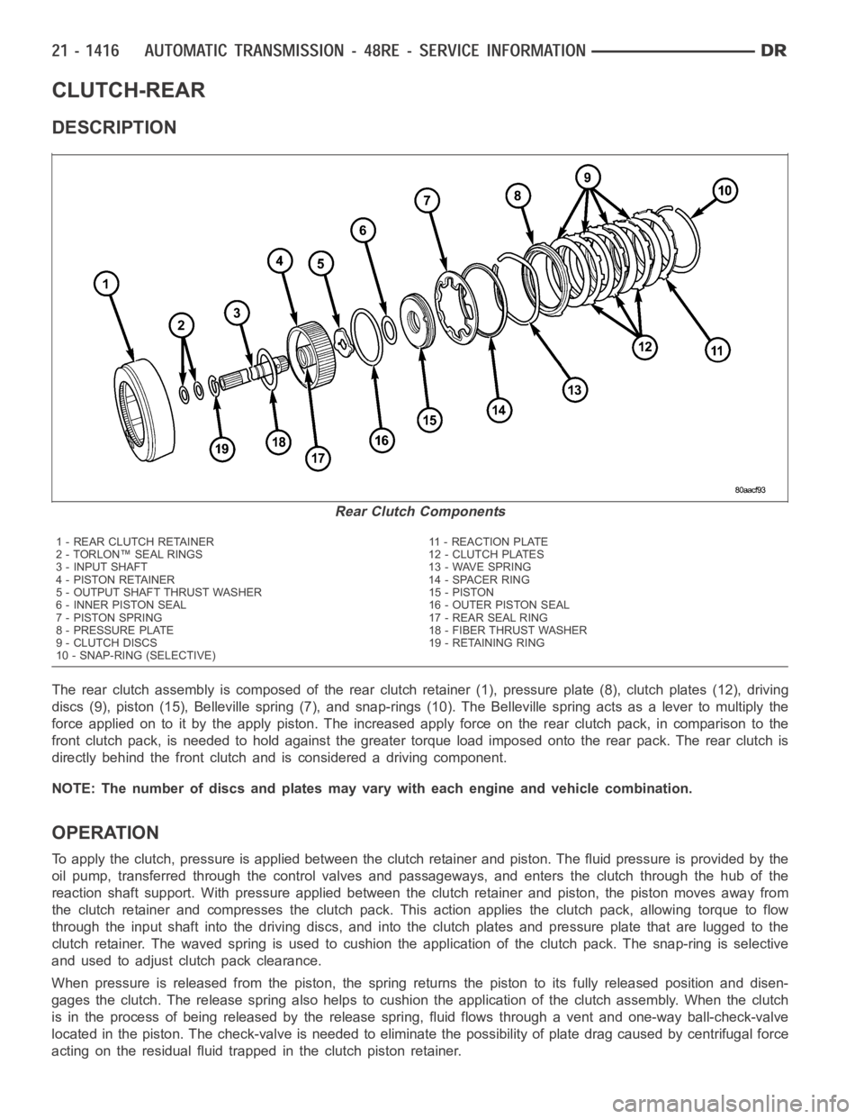
CLUTCH-REAR
DESCRIPTION
The rear clutch assembly is composed of the rear clutch retainer (1), pressure plate (8), clutch plates (12), driving
discs (9), piston (15), Belleville spring (7), and snap-rings (10). The Belleville spring acts as a lever to multiply the
force applied on to it by the apply piston. The increased apply force on the rear clutch pack, in comparison to the
front clutch pack, is needed to hold against the greater torque load imposed onto the rear pack. The rear clutch is
directly behind the front clutch and is considered a driving component.
NOTE: The number of discs and plates may vary with each engine and vehicle combination.
OPERATION
To apply the clutch, pressure is applied between the clutch retainer and piston. The fluid pressure is provided by the
oil pump, transferred through the control valves and passageways, and enters the clutch through the hub of the
reaction shaft support. With pressure applied between the clutch retainer and piston, the piston moves away from
the clutch retainer and compresses the clutch pack. This action applies the clutch pack, allowing torque to flow
through the input shaft into the driving discs, and into the clutch plates and pressure plate that are lugged to the
clutch retainer. The waved spring is used to cushion the application of theclutch pack. The snap-ring is selective
and used to adjust clutch pack clearance.
When pressure is released from the piston, the spring returns the piston toits fully released position and disen-
gages the clutch. The release spring also helps to cushion the applicationof the clutch assembly. When the clutch
is in the process of being released by the release spring, fluid flows through a vent and one-way ball-check-valve
located in the piston. The check-valve is needed to eliminate the possibility of plate drag caused by centrifugal force
acting on the residual fluid trapped in the clutch piston retainer.
Rear Clutch Components
1 - REAR CLUTCH RETAINER 11 - REACTION PLATE
2 - TORLON™ SEAL RINGS 12 - CLUTCH PLATES
3 - INPUT SHAFT 13 - WAVE SPRING
4 - PISTON RETAINER 14 - SPACER RING
5 - OUTPUT SHAFT THRUST WASHER 15 - PISTON
6 - INNER PISTON SEAL 16 - OUTER PISTON SEAL
7 - PISTON SPRING 17 - REAR SEAL RING
8 - PRESSURE PLATE 18 - FIBER THRUST WASHER
9 - CLUTCH DISCS 19 - RETAINING RING
10 - SNAP-RING (SELECTIVE)