check engine DODGE RAM SRT-10 2006 Service Repair Manual
[x] Cancel search | Manufacturer: DODGE, Model Year: 2006, Model line: RAM SRT-10, Model: DODGE RAM SRT-10 2006Pages: 5267, PDF Size: 68.7 MB
Page 5194 of 5267
The following is a list of the system monitors:
Misfire Monitor
Fuel System Monitor
Oxygen Sensor Monitor
Oxygen Sensor Heater Monitor
Catalyst Monitor
Leak Detection Pump Monitor (if equipped)
All these system monitors require two consecutive trips with the malfunction present to set a fault.
Refer to the appropriate Powertrain Diagnostics Procedures manual for diagnostic procedures.
The following is an operation and description of each system monitor:
OXYGEN SENSOR (O2S) MONITOR
Effective control of exhaust emissions is achieved by an oxygen feedback system. The most important element of
the feedback system is the O2S. The O2S is located in the exhaust path. Once it reaches operating temperature
300° to 350°C (572° to 662°F), the sensor generates a voltage that is inversely proportional to the amount of oxy-
gen in the exhaust. The information obtained by the sensor is used to calculate the fuel injector pulse width. This
maintains a 14.7 to 1 Air Fuel (A/F) ratio. At this mixture ratio, the catalyst works best to remove hydrocarbons (HC),
carbon monoxide (CO) and nitrogen oxide (NOx) from the exhaust.
The O2S is also the main sensing element for the Catalyst and Fuel Monitors.
The O2S can fail in any or all of the following manners:
slow response rate
reduced output voltage
dynamic shift
shortedoropencircuits
Response rate is the time required for the sensor to switch from lean to richonce it is exposed to a richer than
optimum A/F mixture or vice versa. As the sensor starts malfunctioning, itcould take longer to detect the changes
in the oxygen content of the exhaust gas.
The output voltage of the O2S ranges from 0 to 1 volt. A good sensor can easilygenerate any output voltage in this
range as it is exposed to different concentrations of oxygen. To detect a shift in the A/F mixture (lean or rich), the
output voltage has to change beyond a threshold value. A malfunctioning sensor could have difficulty changing
beyond the threshold value.
OXYGEN SENSOR HEATER MONITOR
If there is an oxygen sensor (O2S) shorted to voltage DTC, as well as a O2S heater DTC, the O2S fault MUST be
repaired first. Before checking the O2S fault, verify that the heater circuit is operating correctly.
Effective control of exhaust emissions is achieved by an oxygen feedback system. The most important element of
the feedback system is the O2S. The O2S is located in the exhaust path. Once it reaches operating temperature
300°C to 350°C (572°F to 662°F), the sensor generates a voltage that is inversely proportional to the amount of
oxygen in the exhaust. The information obtained by the sensor is used to calculate the fuel injector pulse width. This
maintains a 14.7 to 1 Air Fuel (A/F) ratio. At this mixture ratio, the catalyst works best to remove hydrocarbons (HC),
carbon monoxide (CO) and nitrogen oxide (NOx) from the exhaust.
The voltage readings taken from the O2S sensor are very temperature sensitive. The readings are not accurate
below 572°F (300°C). Heating of the O2S sensor is done to allow the engine controllertoshifttoclosedloopcontrol
as soon as possible. The heating element used to heat the O2S sensor must be testedtoensurethatitisheating
the sensor properly.
The O2S sensor circuit is monitored for a drop in voltage. The sensor outputis used to test the heater by isolating
the effect of the heater element on the O2S sensor output voltage from the other effects.
LEAK DETECTION PUMP MONITOR (IF EQUIPPED)
The leak detection assembly incorporates two primary functions: it must detect a leak in the evaporative system and
seal the evaporative system so the leak detection test can be run.
Page 5195 of 5267
The primary components within the assembly are: A three port solenoid thatactivates both of the functions listed
above; a pump which contains a switch, two check valves and a spring/diaphragm, a canister vent valve (CVV) seal
which contains a spring loaded vent seal valve.
Immediately after a cold start, between predetermined temperature thresholds limits, the three port solenoid is briefly
energized. This initializes the pump by drawing air into the pump cavity and also closes the vent seal. During non
test conditions the vent seal is held open by the pump diaphragm assembly which pushes it open at the full travel
position. The vent seal will remain closed while the pump is cycling due to the reed switch triggering of the three
port solenoid that prevents the diaphragm assembly from reaching full travel. After the brief initialization period, the
solenoid is de-energized allowing atmospheric pressure to enter the pumpcavity, thus permitting the spring to drive
the diaphragm which forces air out of the pump cavity and into the vent system. When the solenoid is energized
and de energized, the cycle is repeated creating flow in typical diaphragmpump fashion. The pump is controlled in
2 modes:
Pump Mode: The pump is cycled at a fixed rate to achieve a rapid pressure build in order to shorten the overall test
length.
Test Mode: The solenoid is energized with a fixed duration pulse. Subsequent fixed pulses occur when the dia-
phragm reaches the Switch closure point.
The spring in the pump is set so that the system will achieve an equalized pressure of about 7.5” H20. The cycle
rate of pump strokes is quite rapid as the system begins to pump up to this pressure. As the pressure increases, the
cycle rate starts to drop off. If there is no leak in the system, the pump would eventually stop pumping at the equal-
ized pressure. If there is a leak, it will continue to pump at a rate representative of the flow characteristic of the size
of the leak. From this information we can determine if the leak is larger than the required detection limit (currently
set at .040” orifice by CARB). If a leak is revealed during the leak test portion of the test, the test is terminated at
the end of the test mode and no further system checks will be performed.
After passing the leak detection phase of the test, system pressure is maintained by turning on the LDP’s solenoid
until the purge system is activated. Purge activation in effect creates a leak. The cycle rate is again interrogated and
when it increases due to the flow through the purge system, the leak check portion of the diagnostic is complete.
The canister vent valve will unseal the system after completion of the testsequence as the pump diaphragm assem-
bly moves to the full travel position.
Evaporative system functionality will be verified by using the stricter evap purge flow monitor. At an appropriate
warm idle the LDP will be energized to seal the canister vent. The purge flowwill be clocked up from some small
value in an attempt to see a shift in the02 control system. If fuel vapor, indicated by a shift in the 02 control, is
present the test is passed. If not, it is assumed that the purge system is notfunctioning in some respect. The LDP
is again turned off and the test is ended.
MISFIRE MONITOR
Excessive engine misfire results in increased catalyst temperature and causes an increase in HC emissions. Severe
misfires could cause catalyst damage. To prevent catalytic convertor damage, the PCM monitors engine misfire.
The Powertrain Control Module (PCM) monitors for misfire during most engine operating conditions (positive torque)
by looking at changes in the crankshaft speed. If a misfire occurs the speedof the crankshaft will vary more than
normal.
FUEL SYSTEM MONITOR
To comply with clean air regulations, vehicles are equipped with catalytic converters. These converters reduce the
emission of hydrocarbons, oxides of nitrogen and carbon monoxide. The catalyst works best when the Air Fuel (A/F)
ratio is at or near the optimum of 14.7 to 1.
The PCM is programmed to maintain the optimum air/fuel ratio of 14.7 to 1. This is done by making short term
corrections in the fuel injector pulse width based on the O2S sensor output. The programmed memory acts as a self
calibration tool that the engine controller uses to compensate for variations in engine specifications, sensor toler-
ances and engine fatigue over the life span of the engine. By monitoring theactual fuel-air ratio with the O2S sen-
sor (short term) and multiplying that with the program long-term (adaptive) memory and comparing that to the limit,
it can be determined whether it will pass an emissions test. If a malfunction occurs such that the PCM cannot main-
tain the optimum A/F ratio, then the MIL will be illuminated.
Page 5197 of 5267
COMPONENT MONITORS
There are several components that will affect vehicle emissions if they malfunction. If one of these components
malfunctions the Malfunction Indicator Lamp (MIL) will illuminate.
Some of the component monitors are checking for proper operation of the part. Electrically operated components
now have input (rationality) and output (functionality) checks. Previously, a component like the Throttle Position sen-
sor (TPS) was checked by the PCM for an open or shorted circuit. If one of these conditions occurred, a DTC was
set. Now there is a check to ensure that the component is working. This is donebywatchingforaTPSindication
of a greater or lesser throttle opening than MAP and engine rpm indicate. Inthe case of the TPS, if engine vacuum
is high and engine rpm is 1600 or greater, and the TPS indicates a large throttle opening, a DTC will be set. The
same applies to low vacuum if the TPS indicates a small throttle opening.
All open/short circuit checks, or any component that has an associated limp-in, will set a fault after 1 trip with the
malfunction present. Components without an associated limp-in will taketwo trips to illuminate the MIL.
OPERATION
OPERATION
The Powertrain Control Module (PCM) monitors many
different circuits in the fuel injection, ignition, emission
and engine systems. If the PCM senses a problem
withamonitoredcircuitoftenenoughtoindicatean
actual problem, it stores a Diagnostic Trouble Code
(DTC) in the PCM’s memory. If the problem is repaired
or ceases to exist, the PCM cancels the code after 40
warm-up cycles. Diagnostic trouble codes that affect
vehicle emissions illuminatethe Malfunction Indicator
Lamp (MIL). The MIL is displayed as an engine icon
(graphic) on the instrument panel. Refer to Malfunction
Indicator Lamp in this section.
Certain criteria must be met before the PCM stores a
DTC in memory. The criteria may be a specific range
of engine RPM, engine temperature, and/or input volt-
age to the PCM.
The PCM might not store a DTC for a monitored cir-
cuit even though a malfunction has occurred. This
may happen because one of the DTC criteria for the
circuit has not been met.For example,assume the diagnostic trouble code criteria requires the PCM to monitor the
circuit only when the engine operates between 750 and 2000 RPM. Suppose thesensor’s output circuit shorts to
ground when engine operates above 2400 RPM (resulting in 0 volt input to thePCM). Because the condition hap-
pens at an engine speed above the maximum threshold (2000 rpm), the PCM willnot store a DTC.
There are several operating conditions for which the PCM monitors and setsDTC’s. Refer to Monitored Systems,
Components, and Non-Monitored Circuits in this section.
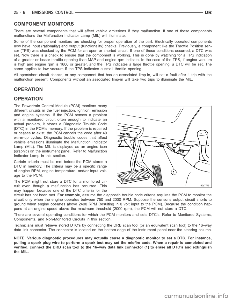
Technicians must retrieve stored DTC’s by connecting the DRB scan tool (oran equivalent scan tool) to the 16–way
data link connector. The connector is located on the bottom edge of the instrument panel near the steering column.
NOTE: Various diagnostic procedures may actually cause a diagnostic monitor to set a DTC. For instance,
pulling a spark plug wire to perform a spark test may set the misfire code. When a repair is completed and
verified, connect the DRB scan tool to the 16–way data link connector (1) toerase all DTC’s and extinguish
the MIL.
Page 5207 of 5267
PUMP-LEAK DETECTION
DESCRIPTION
Vehicles equipped with JTEC engine control modules use a leak detection pump. Vehicles equipped with NGC
engine control modules use an NVLD pump. Refer to Natural Vacuum - Leak Detection (NVLD) for additional infor-
mation.
The evaporative emission system is designed to prevent the escape of fuel vapors from the fuel system. Leaks in
the system, even small ones, can allow fuel vapors to escape into the atmosphere. Government regulations require
onboard testing to make sure that the evaporative (EVAP) system is functioning properly. The leak detection system
tests for EVAP system leaks and blockage. It also performs self-diagnostics. During self-diagnostics, the Powertrain
Control Module (PCM) first checks the Leak Detection Pump (LDP) for electrical and mechanical faults. If the first
checks pass, the PCM then uses the LDP to seal the vent valve and pump air intothe system to pressurize it. If a
leak is present, the PCM will continue pumping the LDP to replace the air that leaks out. The PCM determines the
size of the leak based on how fast/long it must pump the LDP as it tries to maintain pressure in the system.
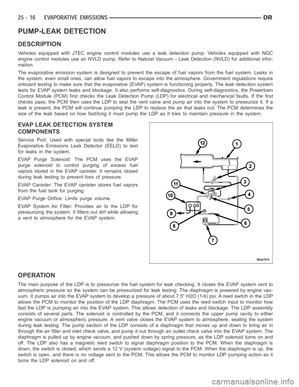
EVAP LEAK DETECTION SYSTEM
COMPONENTS
Service Port: Used with special tools like the Miller
Evaporative Emissions Leak Detector (EELD) to test
for leaks in the system.
EVAP Purge Solenoid: The PCM uses the EVAP
purge solenoid to control purging of excess fuel
vapors stored in the EVAP canister. It remains closed
during leak testing to prevent loss of pressure.
EVAP Canister: The EVAP canister stores fuel vapors
from the fuel tank for purging.
EVAP Purge Orifice: Limits purge volume.
EVAP System Air Filter: Provides air to the LDP for
pressurizing the system. It filters out dirt while allowing
a vent to atmosphere for the EVAP system.
OPERATION
The main purpose of the LDP is to pressurize the fuel system for leak checking. It closes the EVAP system vent to
atmospheric pressure so the system can be pressurized for leak testing. The diaphragm is powered by engine vac-
uum. It pumps air into the EVAP system to develop a pressure of about 7.5
H2O (1/4) psi. A reed switch in the LDP
allows the PCM to monitor the position of the LDP diaphragm. The PCM uses thereed switch input to monitor how
fast the LDP is pumping air into the EVAP system. This allows detection of leaks and blockage. The LDP assembly
consists of several parts. The solenoid is controlled by the PCM, and it connects the upper pump cavity to either
engine vacuum or atmospheric pressure. A vent valve closes the EVAP systemto atmosphere, sealing the system
during leak testing. The pump section of the LDP consists of a diaphragm that moves up and down to bring air in
through the air filter and inlet check valve, and pump it out through an outlet check valve into the EVAP system. The
diaphragm is pulled up by engine vacuum, and pushed down by spring pressure, as the LDP solenoid turns on and
off. The LDP also has a magnetic reed switch to signal diaphragm position tothe PCM. When the diaphragm is
down, the switch is closed, which sends a 12 V (system voltage) signal to thePCM. When the diaphragm is up, the
switch is open, and there is no voltage sent to the PCM. This allows the PCM tomonitor LDP pumping action as it
turns the LDP solenoid on and off.
Page 5208 of 5267
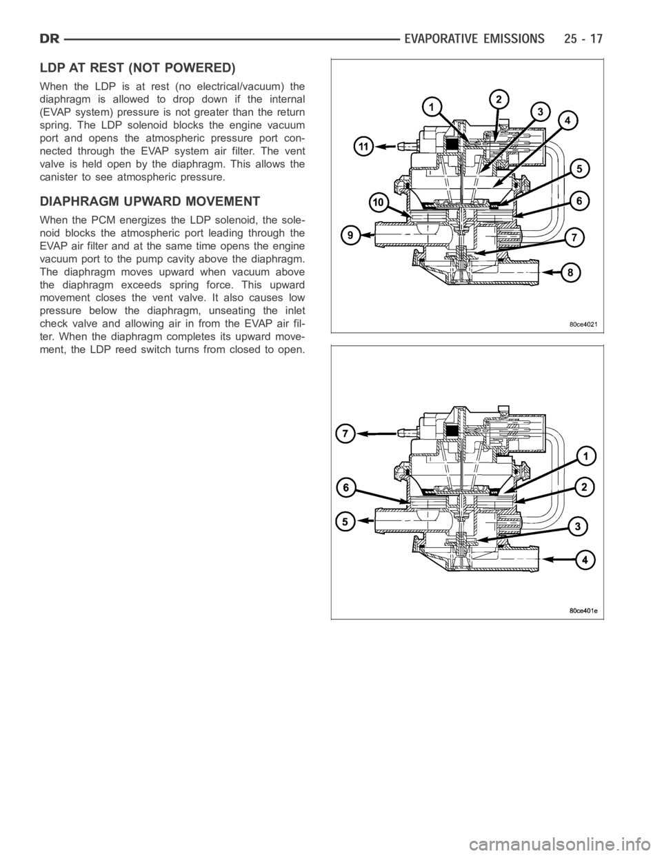
LDP AT REST (NOT POWERED)
When the LDP is at rest (no electrical/vacuum) the
diaphragm is allowed to drop down if the internal
(EVAP system) pressure is not greater than the return
spring. The LDP solenoid blocks the engine vacuum
port and opens the atmospheric pressure port con-
nected through the EVAP system air filter. The vent
valve is held open by the diaphragm. This allows the
canister to see atmospheric pressure.
DIAPHRAGM UPWARD MOVEMENT
When the PCM energizes the LDP solenoid, the sole-
noid blocks the atmospheric port leading through the
EVAP air filter and at the same time opens the engine
vacuum port to the pump cavity above the diaphragm.
The diaphragm moves upward when vacuum above
the diaphragm exceeds spring force. This upward
movement closes the vent valve. It also causes low
pressure below the diaphragm, unseating the inlet
check valve and allowing air in from the EVAP air fil-
ter. When the diaphragm completes its upward move-
ment, the LDP reed switch turns from closed to open.
Page 5212 of 5267
ORVR
DESCRIPTION
The ORVR (On-Board Refueling Vapor Recovery) system consists of a unique fuel tank, flow management valve,
fluid control valve, one-way check valve and vapor canister.
OPERATION
The ORVR (On-Board Refueling Vapor Recovery) system is used to remove excess fuel tank vapors. This is done
while the vehicle is being refueled.
Fuel flowing into the fuel filler tube (approx. 1” I.D.) creates an aspiration effect drawing air into the fuel fill tube.
During refueling, the fuel tank is vented to the EVAP canister to capture escaping vapors. With air flowing into the
filler tube, there are no fuel vapors escaping to the atmosphere. Once the refueling vapors are captured by the
EVAP canister, the vehicle’s computer controlled purge system draws vapor out of the canister for the engine to
burn. The vapor flow is metered by the purge solenoid so that there is no, or minimal impact on driveability or
tailpipe emissions.
As fuel starts to flow through the fuel fill tube, it opens the normally closed check valve and enters the fuel tank.
Vapor or air is expelled from the tank through the control valve and on to thevapor canister. Vapor is absorbed in
the EVAP canister until vapor flow in the lines stops. This stoppage occursfollowing fuel shut-off, or by having the
fuel level in the tank rise high enough to close the control valve. This control valve contains a float that rises to seal
the large diameter vent path to the EVAP canister. At this point in the refueling process, fuel tank pressure
increases, the check valve closes (preventing liquid fuel from spiting back at the operator), and fuel then rises up
the fuel filler tube to shut off the dispensing nozzle.
Page 5213 of 5267
PUMP-NATURAL VAC LEAK DETECTION
DESCRIPTION
Vehicles equipped with an NGC Powertrain Control Module (PCM) use a Natural Vacuum Leak Detection (NVLD)
pump and system. Vehicles equipped with a JTEC PCM use an LDP (Leak Detection Pump). Refer to Leak Detec-
tion Pump (LDP) for additional information.
The NVLD pump is located in the same area as the leak detection pump. Refer toNVLD Removal / Installation for
additional information.
OPERATION
The Natural Vacuum Leak Detection (NVLD) system is the next generation evaporative leak detection system that
will first be used on vehicles equipped with the Next Generation Controller (NGC). This new system replaces the
leak detection pump as the method of evaporative system leak detection. This is to detect a leak equivalent to a
0.020
(0.5 mm) hole. This system has the capability to detect holes of this size very dependably.
The basic leak detection theory employed with NVLD is the
Gas Law. This is to say that the pressure in a sealed
vessel will change if the temperature of the gas in the vessel changes. The vessel will only see this effect if it is
indeed sealed. Even small leaks will allow the pressure in the vessel to come to equilibrium with the ambient pres-
sure. In addition to the detection of very small leaks, this system has the capability of detecting medium as well as
large evaporative system leaks.
A vent valve seals the canister vent during engine off conditions. If the vapor system has a leak of less than the
failure threshold, the evaporativesystem will be pulled into a vacuum, either due to the cool down from operating
temperature or diurnal ambient temperature cycling. The diurnal effect is considered one of the primary contributors
to the leak determination by this diagnostic. When the vacuum in the systemexceeds about 1
H2O (0.25 KPA), a
vacuum switch closes. The switch closure sends a signal to the NGC. The NGC,via appropriate logic strategies,
utilizes the switch signal, or lack thereof, to make a determination of whether a leak is present.
The NVLD device is designed with a normally open vacuum switch, a normally closed solenoid, and a seal, which
is actuated by both the solenoid and a diaphragm. The NVLD is located on the atmospheric vent side of the can-
ister. The NVLD assembly may be mounted on top of the canister outlet, or in-line between the canister and atmo-
spheric vent filter. The normally open vacuum switch will close with about1
H2O (0.25 KPA) vacuum in the
evaporative system. The diaphragm actuates the switch. This is above the opening point of the fuel inlet check valve
in the fill tube so cap off leaks can be detected. Submerged fill systems must have recirculation lines that do not
have the in-line normally closed check valve that protects the system fromfailednozzleliquidingestion,inorderto
detect cap off conditions.
The normally closed valve in the NVLD is intended to maintain the seal on theevaporative system during the engine
off condition. If vacuum in the evaporative system exceeds 3
to 6H2O (0.75 to 1.5 KPA), the valve will be pulled
off the seat, opening the seal. This will protect the system from excessivevacuum as well as allowing sufficient
purge flow in the event that the solenoid was to become inoperative.
The solenoid actuates the valve to unseal the canister vent while the engine is running. It also will be used to close
the vent during the medium and large leak tests and during the purge flow check. This solenoid requires an initial
1.5 amps of current to pull the valveopen, but after 100 mili-seconds, willbedutycycleddowntoanaverageof
about 150 mA for the remainder of the drive cycle.
Another feature in the device is a diaphragm that will open the seal in the NVLD with pressure in the evaporative
system. The device will
blow offat about 0.5H2O (0.12 KPA) pressure to permit the venting of vapors during
refueling. An added benefit to this is that it will also allow the tank to
breatheduring increasing temperatures, thus
limiting the pressure in the tank to this low level. This is beneficial because the induced vacuum during a subse-
quent declining temperature will achieve the switch closed (pass threshold) sooner than if the tank had to decay
from a built up pressure.
The device itself has 3 wires: Switch sense, solenoid driver and ground. Italso includes a resistor to protect the
switch from a short to battery or a short to ground. The NGC utilizes a high-side driver to energize and duty-cycle
the solenoid.
Page 5224 of 5267
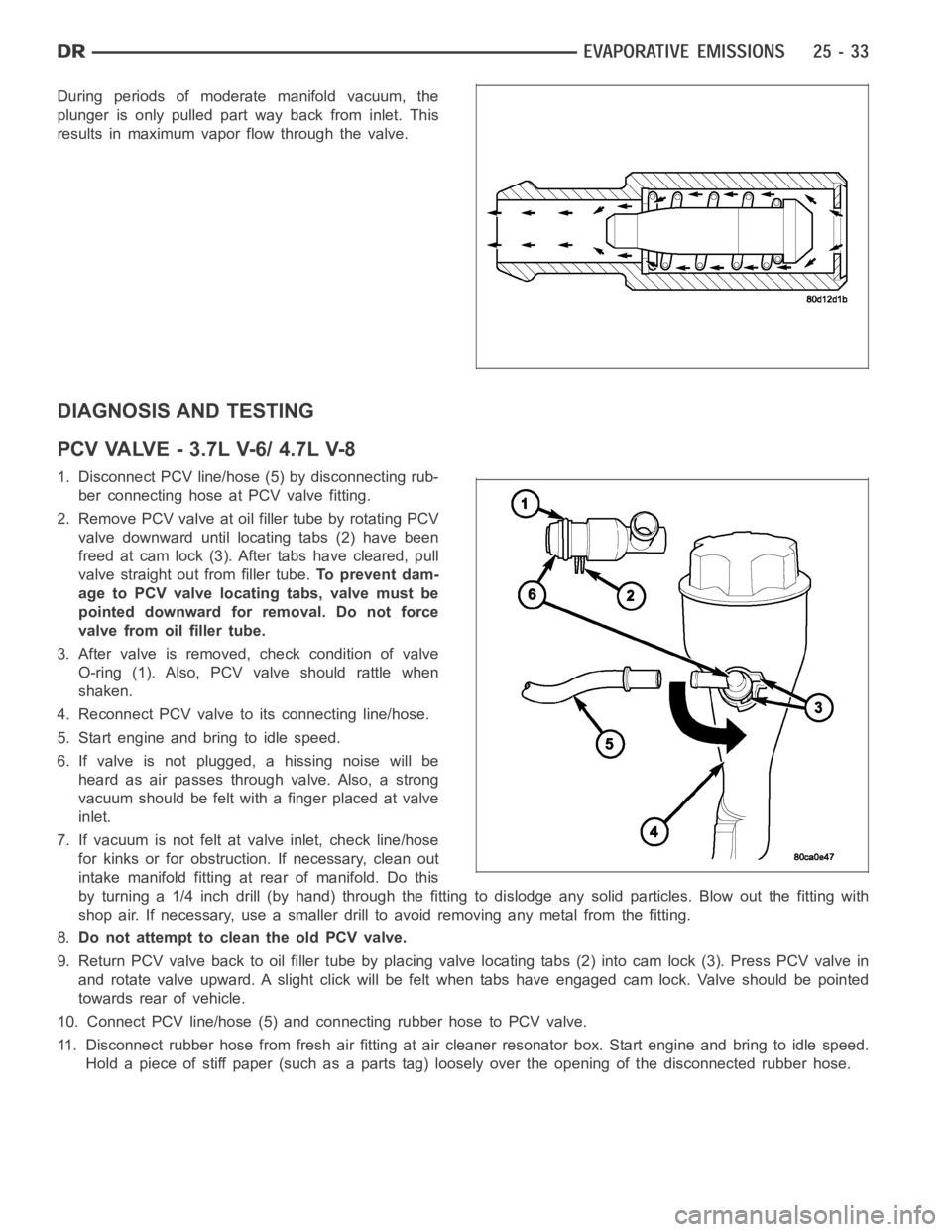
During periods of moderate manifold vacuum, the
plunger is only pulled part way back from inlet. This
results in maximum vapor flow through the valve.
DIAGNOSIS AND TESTING
PCVVALVE-3.7LV-6/4.7LV-8
1. Disconnect PCV line/hose (5) by disconnecting rub-
ber connecting hose at PCV valve fitting.
2. Remove PCV valve at oil filler tube by rotating PCV
valve downward until locating tabs (2) have been
freed at cam lock (3). After tabs have cleared, pull
valve straight out from filler tube.To prevent dam-
age to PCV valve locating tabs, valve must be
pointed downward for removal. Do not force
valve from oil filler tube.
3. After valve is removed, check condition of valve
O-ring (1). Also, PCV valve should rattle when
shaken.
4. Reconnect PCV valve to its connecting line/hose.
5. Start engine and bring to idle speed.
6. If valve is not plugged, a hissing noise will be
heard as air passes through valve. Also, a strong
vacuum should be felt with a finger placed at valve
inlet.
7. If vacuum is not felt at valve inlet, check line/hose
for kinks or for obstruction. If necessary, clean out
intake manifold fitting at rear of manifold. Do this
byturninga1/4inchdrill(byhand)throughthefittingtodislodgeanysolid particles. Blow out the fitting with
shop air. If necessary, use a smaller drill to avoid removing any metal fromthe fitting.
8.Do not attempt to clean the old PCV valve.
9. Return PCV valve back to oil filler tube by placing valve locating tabs (2) into cam lock (3). Press PCV valve in
and rotate valve upward. A slight click will be felt when tabs have engaged cam lock. Valve should be pointed
towards rear of vehicle.
10. Connect PCV line/hose (5) and connecting rubber hose to PCV valve.
11. Disconnect rubber hose from fresh air fitting at air cleaner resonatorbox. Start engine and bring to idle speed.
Hold a piece of stiff paper (such as a parts tag) loosely over the opening of the disconnected rubber hose.
Page 5227 of 5267
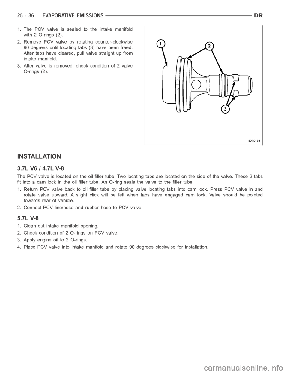
1. The PCV valve is sealed to the intake manifold
with 2 O-rings (2).
2. Remove PCV valve by rotating counter-clockwise
90 degrees until locating tabs (3) have been freed.
After tabs have cleared, pull valve straight up from
intake manifold.
3. After valve is removed, check condition of 2 valve
O-rings (2).
INSTALLATION
3.7L V6 / 4.7L V-8
The PCV valve is located on the oil filler tube. Two locating tabs are locatedonthesideofthevalve.These2tabs
fit into a cam lock in the oil filler tube.An O-ring seals the valve to the filler tube.
1. Return PCV valve back to oil filler tube by placing valve locating tabs into cam lock. Press PCV valve in and
rotate valve upward. A slight click will be felt when tabs have engaged cam lock. Valve should be pointed
towards rear of vehicle.
2. Connect PCV line/hose and rubber hose to PCV valve.
5.7L V-8
1. Clean out intake manifold opening.
2. Check condition of 2 O-rings on PCV valve.
3. Apply engine oil to 2 O-rings.
4. Place PCV valve into intake manifold and rotate 90 degrees clockwise forinstallation.