sensor DODGE RAM SRT-10 2006 Service Repair Manual
[x] Cancel search | Manufacturer: DODGE, Model Year: 2006, Model line: RAM SRT-10, Model: DODGE RAM SRT-10 2006Pages: 5267, PDF Size: 68.7 MB
Page 4116 of 5267
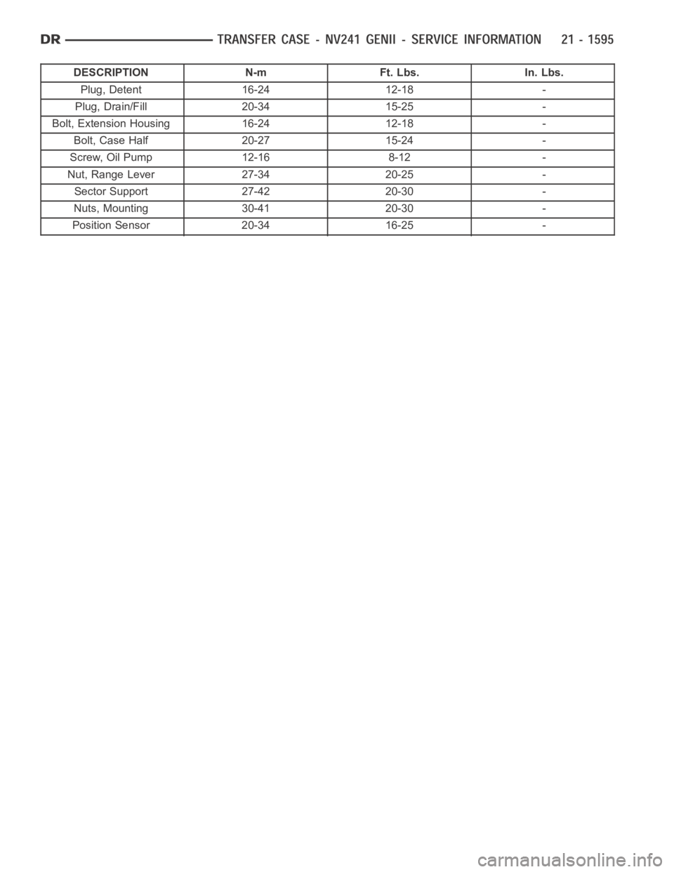
DESCRIPTION N-m Ft. Lbs. In. Lbs.
Plug, Detent 16-24 12-18 -
Plug, Drain/Fill 20-34 15-25 -
Bolt, Extension Housing 16-24 12-18 -
Bolt, Case Half 20-27 15-24 -
Screw, Oil Pump 12-16 8-12 -
Nut, Range Lever 27-34 20-25 -
Sector Support 27-42 20-30 -
Nuts, Mounting 30-41 20-30 -
Position Sensor 20-34 16-25 -
Page 4126 of 5267
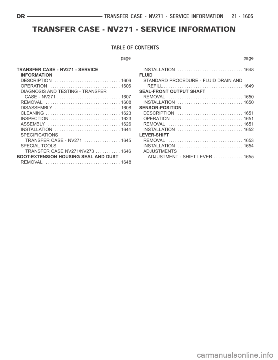
page page
TRANSFER CASE - NV271 - SERVICE
INFORMATION
DESCRIPTION ............................. 1606
OPERATION ............................... 1606
DIAGNOSIS AND TESTING - TRANSFER
CASE - NV271 ............................ 1607
REMOVAL ................................. 1608
DISASSEMBLY ............................. 1608
CLEANING ................................. 1623
INSPECTION ............................... 1623
ASSEMBLY . ............................... 1626
INSTALLATION ............................. 1644
SPECIFICATIONS
TRANSFER CASE - NV271 ................ 1645
SPECIAL TOOLS
TRANSFER CASE NV271/NV273 ........... 1646
BOOT-EXTENSION HOUSING SEAL AND DUST
REMOVAL ................................. 1648INSTALLATION ............................. 1648
FLUID
STANDARD PROCEDURE - FLUID DRAIN AND
REFILL ................................... 1649
SEAL-FRONT OUTPUT SHAFT
REMOVAL ................................. 1650
INSTALLATION ............................. 1650
SENSOR-POSITION
DESCRIPTION ............................. 1651
OPERATION ............................... 1651
REMOVAL ................................. 1651
INSTALLATION ............................. 1652
LEVER-SHIFT
REMOVAL ................................. 1653
INSTALLATION ............................. 1654
ADJUSTMENTS
ADJUSTMENT - SHIFT LEVER............. 1655
Page 4129 of 5267
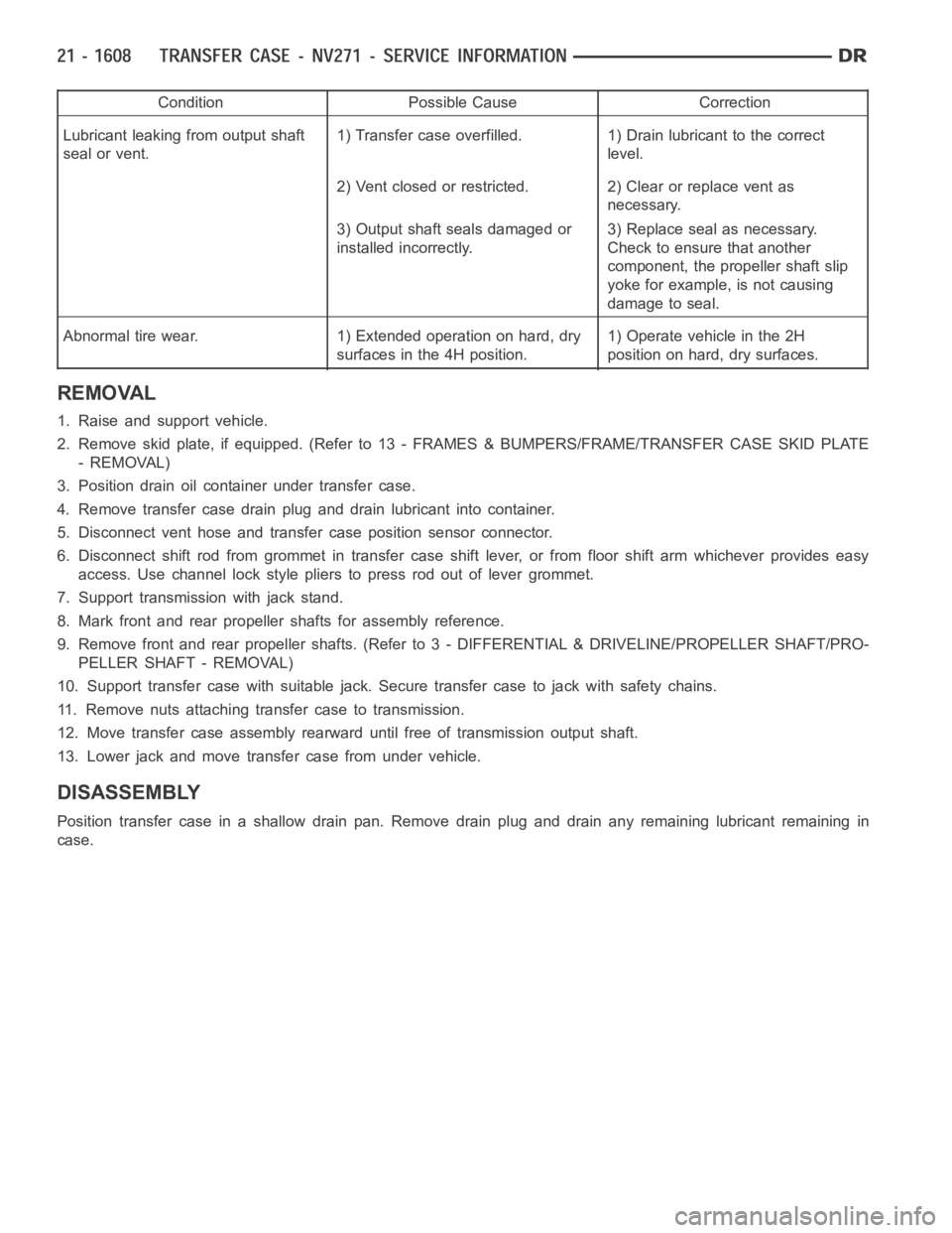
Condition Possible Cause Correction
Lubricant leaking from output shaft
seal or vent.1) Transfer case overfilled. 1) Drain lubricant to the correct
level.
2) Vent closed or restricted. 2) Clear or replace vent as
necessary.
3) Output shaft seals damaged or
installed incorrectly.3) Replace seal as necessary.
Check to ensure that another
component, the propeller shaft slip
yoke for example, is not causing
damage to seal.
Abnormal tire wear. 1) Extended operation on hard, dry
surfaces in the 4H position.1) Operate vehicle in the 2H
position on hard, dry surfaces.
REMOVAL
1. Raise and support vehicle.
2. Remove skid plate, if equipped. (Refer to 13 - FRAMES & BUMPERS/FRAME/TRANSFER CASE SKID PLATE
- REMOVAL)
3. Position drain oil container under transfer case.
4. Remove transfer case drain plug and drain lubricant into container.
5. Disconnect vent hose and transfer case position sensor connector.
6. Disconnect shift rod from grommet in transfer case shift lever, or from floor shift arm whichever provides easy
access. Use channel lock style pliers to press rod out of lever grommet.
7. Support transmission with jack stand.
8. Mark front and rear propeller shafts for assembly reference.
9. Remove front and rear propeller shafts. (Refer to 3 - DIFFERENTIAL & DRIVELINE/PROPELLER SHAFT/PRO-
PELLER SHAFT - REMOVAL)
10. Support transfer case with suitable jack. Secure transfer case to jackwith safety chains.
11. Remove nuts attaching transfer case to transmission.
12. Move transfer case assembly rearward until free of transmission outputshaft.
13. Lower jack and move transfer case from under vehicle.
DISASSEMBLY
Position transfer case in a shallow drain pan. Remove drain plug and drain any remaining lubricant remaining in
case.
Page 4137 of 5267
SHIFT FORKS AND MAINSHAFT
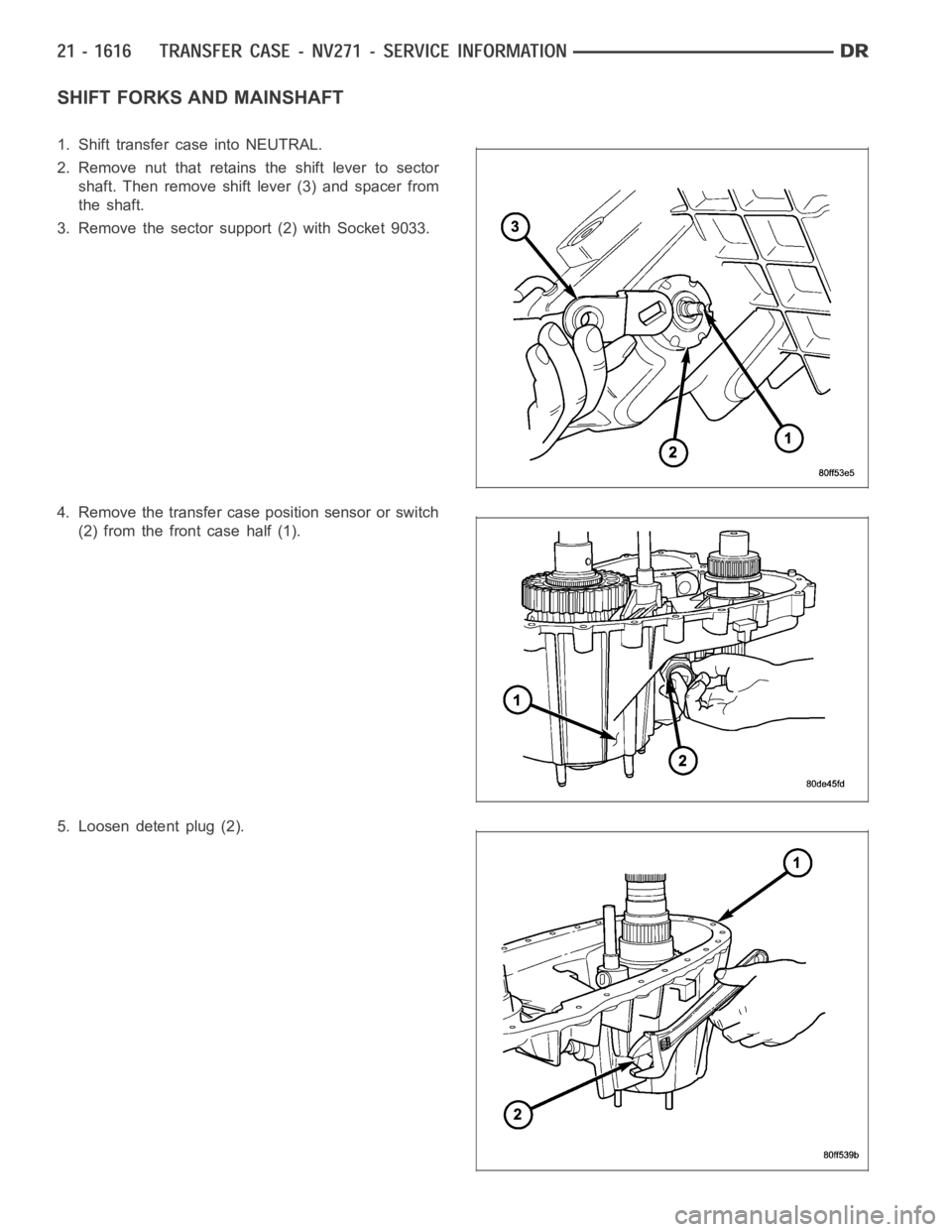
1. Shift transfer case into NEUTRAL.
2. Remove nut that retains the shift lever to sector
shaft. Then remove shift lever (3) and spacer from
the shaft.
3. Remove the sector support (2) with Socket 9033.
4. Remove the transfer case position sensor or switch
(2) from the front case half (1).
5. Loosen detent plug (2).
Page 4158 of 5267
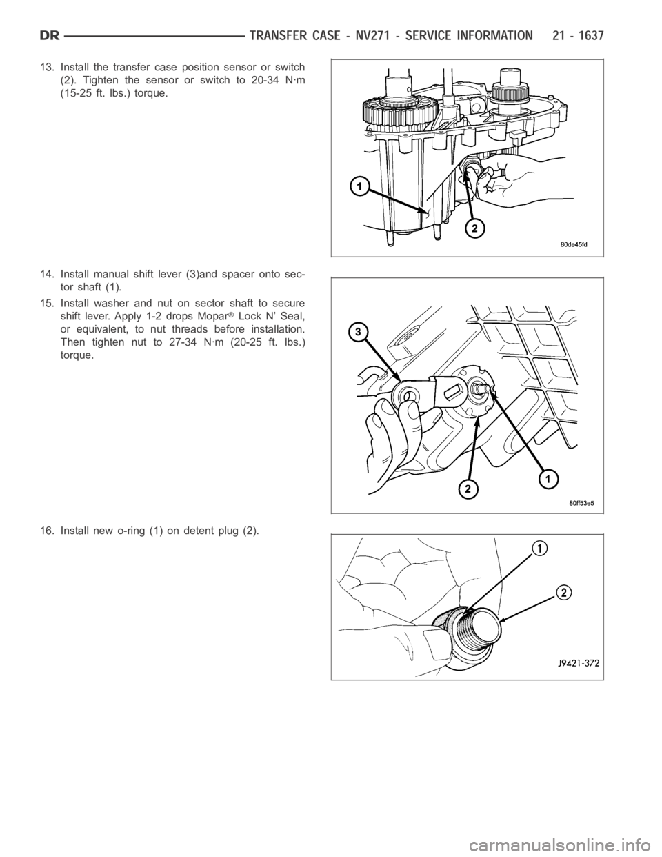
13. Install the transfer case position sensor or switch
(2). Tighten the sensor or switch to 20-34 Nꞏm
(15-25 ft. lbs.) torque.
14. Install manual shift lever (3)and spacer onto sec-
tor shaft (1).
15. Install washer and nut on sector shaft to secure
shift lever. Apply 1-2 drops Mopar
Lock N’ Seal,
or equivalent, to nut threads before installation.
Then tighten nut to 27-34 Nꞏm (20-25 ft. lbs.)
torque.
16. Install new o-ring (1) on detent plug (2).
Page 4165 of 5267
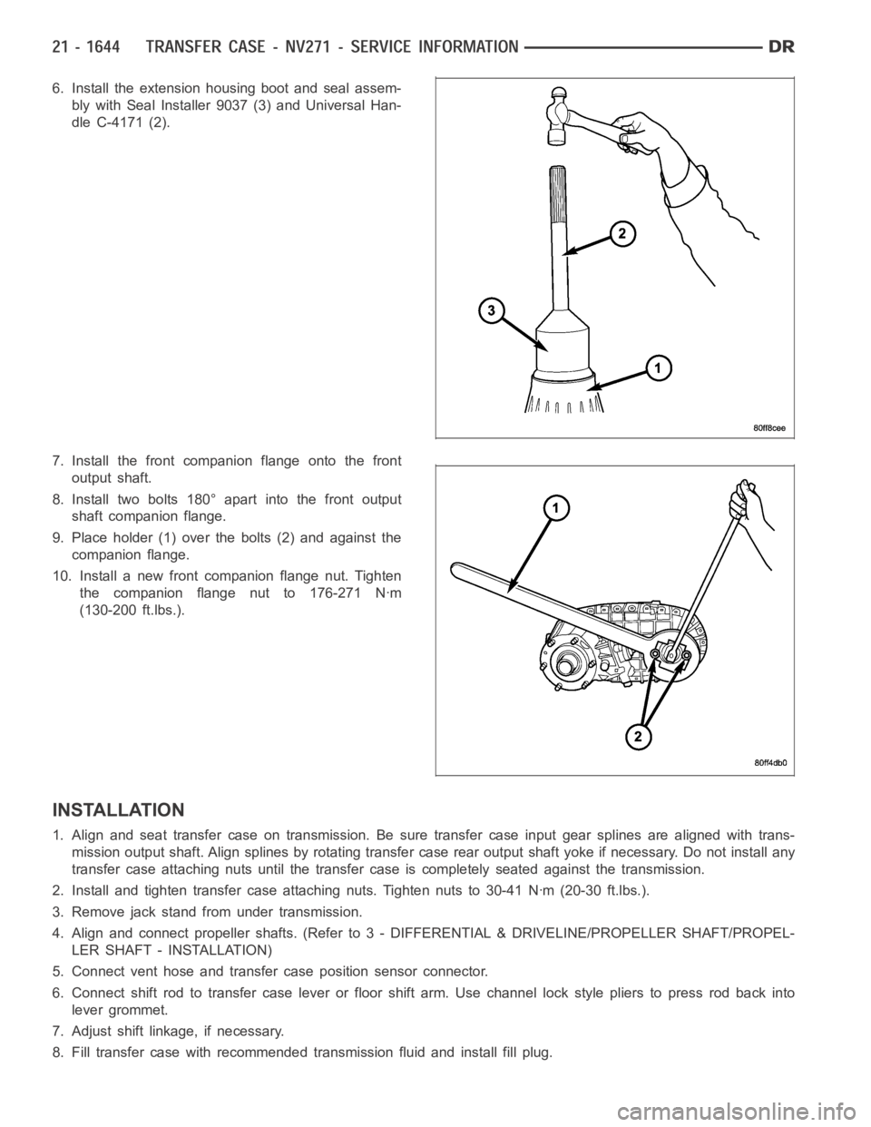
6. Install the extension housing boot and seal assem-
bly with Seal Installer 9037 (3) and Universal Han-
dle C-4171 (2).
7. Install the front companion flange onto the front
output shaft.
8. Install two bolts 180° apart into the front output
shaft companion flange.
9. Place holder (1) over the bolts (2) and against the
companion flange.
10. Install a new front companion flange nut. Tighten
the companion flange nut to 176-271 Nꞏm
(130-200 ft.lbs.).
INSTALLATION
1. Align and seat transfer case on transmission. Be sure transfer case input gear splines are aligned with trans-
mission output shaft. Align splines by rotating transfer case rear outputshaft yoke if necessary. Do not install any
transfer case attaching nuts until the transfer case is completely seatedagainst the transmission.
2. Install and tighten transfer case attaching nuts. Tighten nuts to 30-41Nꞏm (20-30 ft.lbs.).
3. Remove jack stand from under transmission.
4. Align and connect propeller shafts. (Refer to 3 - DIFFERENTIAL & DRIVELINE/PROPELLER SHAFT/PROPEL-
LER SHAFT - INSTALLATION)
5. Connect vent hose and transfer case position sensor connector.
6. Connect shift rod to transfer case lever or floor shift arm. Use channel lock style pliers to press rod back into
lever grommet.
7. Adjust shift linkage, if necessary.
8. Fill transfer case with recommended transmission fluid and install fillplug.
Page 4166 of 5267
9. Install skid plate, if equipped. (Refer to 13 - FRAMES & BUMPERS/FRAME/TRANSFER CASE SKID PLATE -
INSTALLATION)
10. Lower vehicle
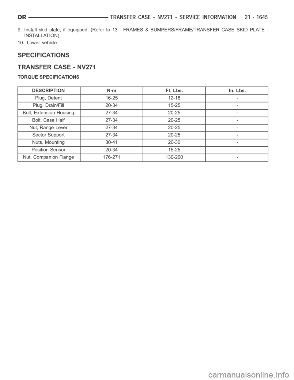
SPECIFICATIONS
TRANSFER CASE - NV271
TORQUE SPECIFICATIONS
DESCRIPTION N-m Ft. Lbs. In. Lbs.
Plug, Detent 16-25 12-18 -
Plug, Drain/Fill 20-34 15-25 -
Bolt, Extension Housing 27-34 20-25 -
Bolt, Case Half 27-34 20-25 -
Nut, Range Lever 27-34 20-25 -
Sector Support 27-34 20-25 -
Nuts, Mounting 30-41 20-30 -
Position Sensor 20-34 15-25 -
Nut, Companion Flange 176-271 130-200 -
Page 4172 of 5267
SENSOR-POSITION
DESCRIPTION
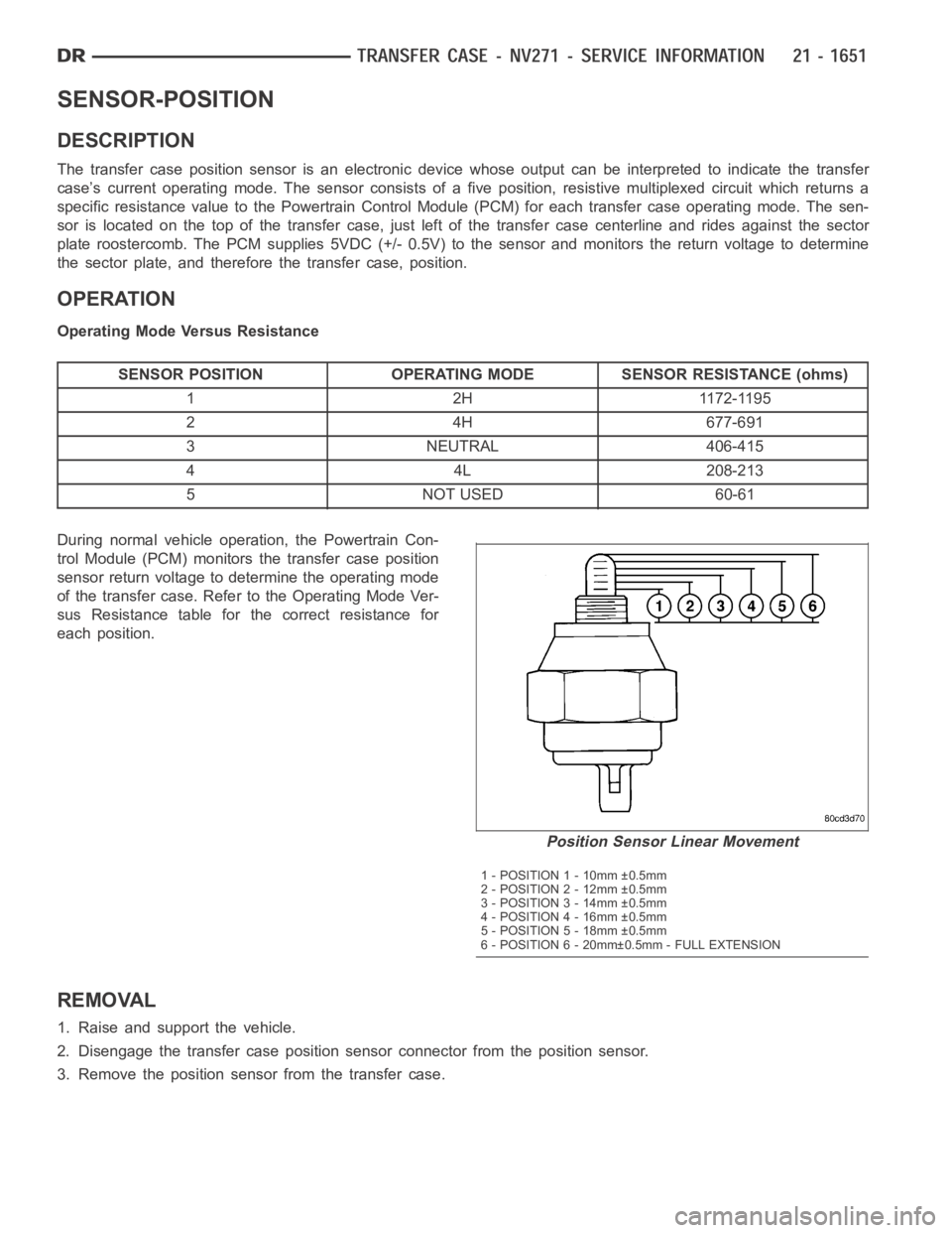
The transfer case position sensor is an electronic device whose output canbe interpreted to indicate the transfer
case’s current operating mode. The sensor consists of a five position, resistive multiplexed circuit which returns a
specific resistance value to the Powertrain Control Module (PCM) for eachtransfer case operating mode. The sen-
sor is located on the top of the transfer case, just left of the transfer casecenterline and rides against the sector
plate roostercomb. The PCM supplies 5VDC (+/- 0.5V) to the sensor and monitors the return voltage to determine
the sector plate, and therefore the transfer case, position.
OPERATION
Operating Mode Versus Resistance
SENSOR POSITION OPERATING MODE SENSOR RESISTANCE (ohms)
1 2H 1172-1195
24H677-691
3 NEUTRAL 406-415
44L208-213
5 NOT USED 60-61
During normal vehicle operation, the Powertrain Con-
trol Module (PCM) monitors the transfer case position
sensor return voltage to determine the operating mode
of the transfer case. Refer to the Operating Mode Ver-
sus Resistance table for the correct resistance for
each position.
REMOVAL
1. Raise and support the vehicle.
2. Disengage the transfer case position sensor connector from the positionsensor.
3. Remove the position sensor from the transfer case.
Position Sensor Linear Movement
1 - POSITION 1 - 10mm ±0.5mm
2 - POSITION 2 - 12mm ±0.5mm
3 - POSITION 3 - 14mm ±0.5mm
4 - POSITION 4 - 16mm ±0.5mm
5 - POSITION 5 - 18mm ±0.5mm
6 - POSITION 6 - 20mm±0.5mm - FULL EXTENSION
Page 4173 of 5267
INSTALLATION
1. Inspect the o-ring seal on the transfer case position sensor. Replace the o-ring if necessary.
2. Install the transfer case position sensor into the transfer case. Torque the sensor to 27 Nꞏm (20 ft.lbs.).
3. Engage the transfer case position sensor connector to the position sensor.
4. Lower vehicle.
5. Verify proper sensor operation.
Page 4177 of 5267
page page
TRANSFER CASE - NV243 - SERVICE
INFORMATION
DESCRIPTION ............................. 1657
OPERATION ............................... 1657
DIAGNOSIS AND TESTING - TRANSFER
CASE - NV243 ............................ 1658
REMOVAL ................................. 1659
DISASSEMBLY ............................. 1659
CLEANING ................................. 1671
INSPECTION ............................... 1671
ASSEMBLY . ............................... 1674
INSTALLATION ............................. 1686
SPECIFICATIONS
TRANSFER CASE - NV243 ................ 1686
SPECIAL TOOLS
TRANSFER CASE - NV243 ................ 1687
SEAL-EXTENSION HOUSING
REMOVAL ................................. 1689
INSTALLATION ............................. 1689
FLUID
STANDARD PROCEDURE - FLUID DRAIN AND
REFILL ................................... 1690SEAL-FRONT OUTPUT SHAFT
REMOVAL ................................. 1691
INSTALLATION ............................. 1692
SENSOR-MODE
DESCRIPTION ............................. 1693
OPERATION ............................... 1693
SWITCH-SELECTOR
DESCRIPTION ............................. 1695
OPERATION ............................... 1695
MOTOR-SHIFT
DESCRIPTION ............................. 1697
OPERATION ............................... 1697
REMOVAL ................................. 1697
INSTALLATION ............................. 1697
ASSEMBLY-SHIFT MOTOR/MODE SENSOR
DESCRIPTION ............................. 1699
OPERATION ............................... 1699