DODGE RAM SRT-10 2006 Service Repair Manual
Manufacturer: DODGE, Model Year: 2006, Model line: RAM SRT-10, Model: DODGE RAM SRT-10 2006Pages: 5267, PDF Size: 68.7 MB
Page 1701 of 5267
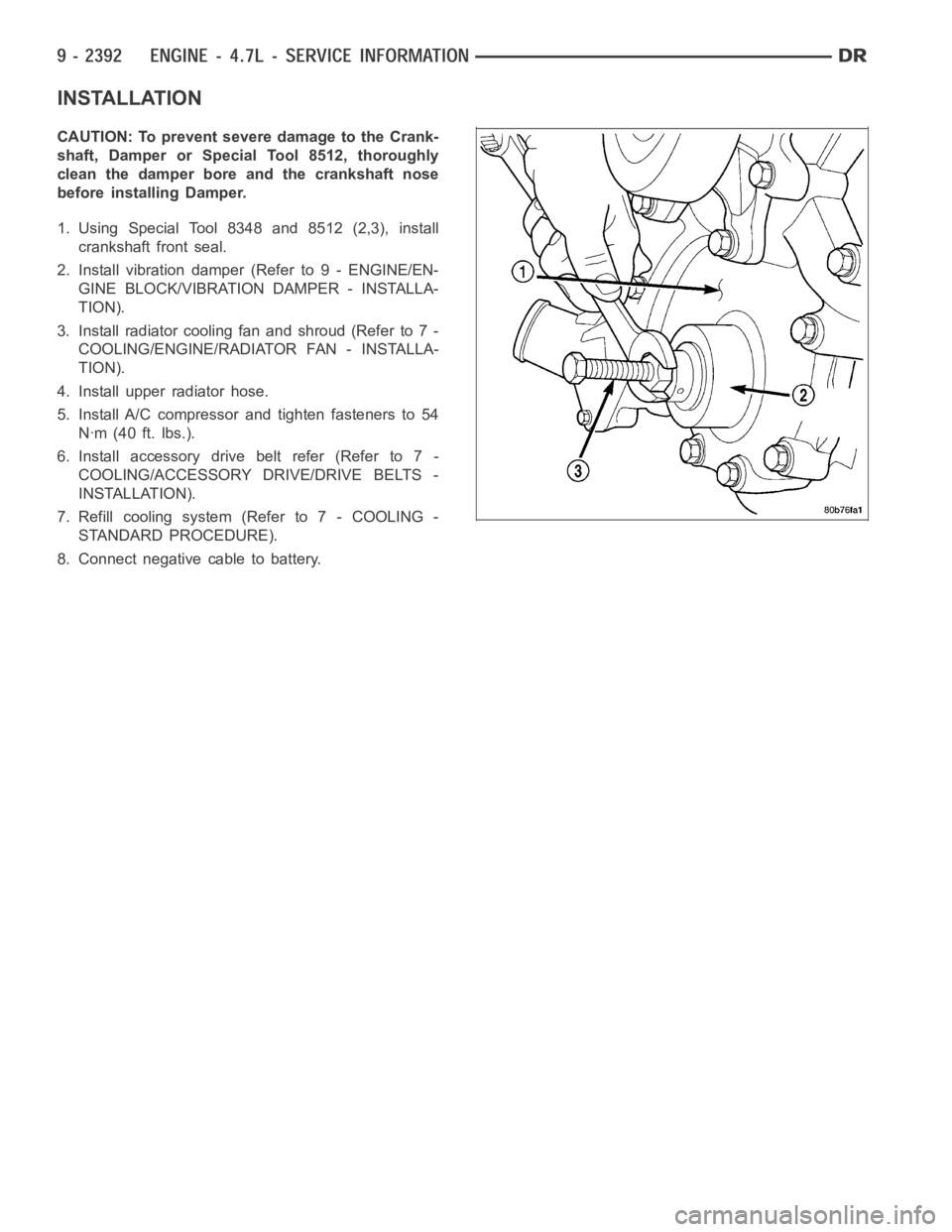
INSTALLATION
CAUTION: To prevent severe damage to the Crank-
shaft, Damper or Special Tool 8512, thoroughly
clean the damper bore and the crankshaft nose
before installing Damper.
1. Using Special Tool 8348 and 8512 (2,3), install
crankshaft front seal.
2. Install vibration damper (Refer to 9 - ENGINE/EN-
GINE BLOCK/VIBRATION DAMPER - INSTALLA-
TION).
3. Installradiatorcoolingfanandshroud(Referto7-
COOLING/ENGINE/RADIATOR FAN - INSTALLA-
TION).
4. Install upper radiator hose.
5. Install A/C compressor and tighten fasteners to 54
Nꞏm (40 ft. lbs.).
6. Install accessory drive belt refer (Refer to 7 -
COOLING/ACCESSORY DRIVE/DRIVE BELTS -
INSTALLATION).
7. Refill cooling system (Refer to 7 - COOLING -
STANDARD PROCEDURE).
8. Connect negative cable to battery.
Page 1702 of 5267
SEAL - CRANKSHAFT OIL - REAR
DIAGNOSIS AND TESTING - REAR SEAL AREA LEAKS
Since it is sometimes difficult to determine the source of an oil leak in therear seal area of the engine, a more
involved inspection is necessary. The following steps should be followedto help pinpoint the source of the leak.
If the leakage occurs at the crankshaft rear oil seal area:
1. Disconnect the battery.
2. Raise the vehicle.
3. Remove torque converter or clutch housing cover and inspect rear of block for evidence of oil. Use a black light
to check for the oil leak:
a. Circular spray pattern generally indicates seal leakage or crankshaftdamage.
b. Where leakage tends to run straight down, possible causes are a porous block, oil galley pipe plugs, oil filter
runoff, and main bearing cap to cylinder block mating surfaces. See Engine, for proper repair procedures of
these items.
4. If no leaks are detected, pressurized the crankcase as outlined in the section, Inspection (Engine oil Leaks in
general)
CAUTION: Do not exceed 20.6 kPa (3 psi).
5. If the leak is not detected, very slowly turn the crankshaft and watch forleakage. If a leak is detected between
the crankshaft and seal while slowly turning the crankshaft, it is possible the crankshaft seal surface is damaged.
The seal area on the crankshaft could have minor nicks or scratches that canbe polished out with emery cloth.
CAUTION: Use extreme caution when crankshaft polishing is necessary to remove minor nicks or
scratches. The crankshaft seal flange is specially machined to complement the function of the rear oil seal.
6. For bubbles that remain steady with shaft rotation, no further inspection can be done until disassembled. (Refer
to 9 - ENGINE - DIAGNOSIS AND TESTING), under the Oil Leak row, for components inspections on possible
causes and corrections.
7. After the oil leak root cause and appropriate corrective action have been identified, (Refer to 9 - ENGINE/EN-
GINE BLOCK/CRANKSHAFT OIL SEAL - REAR - REMOVAL).
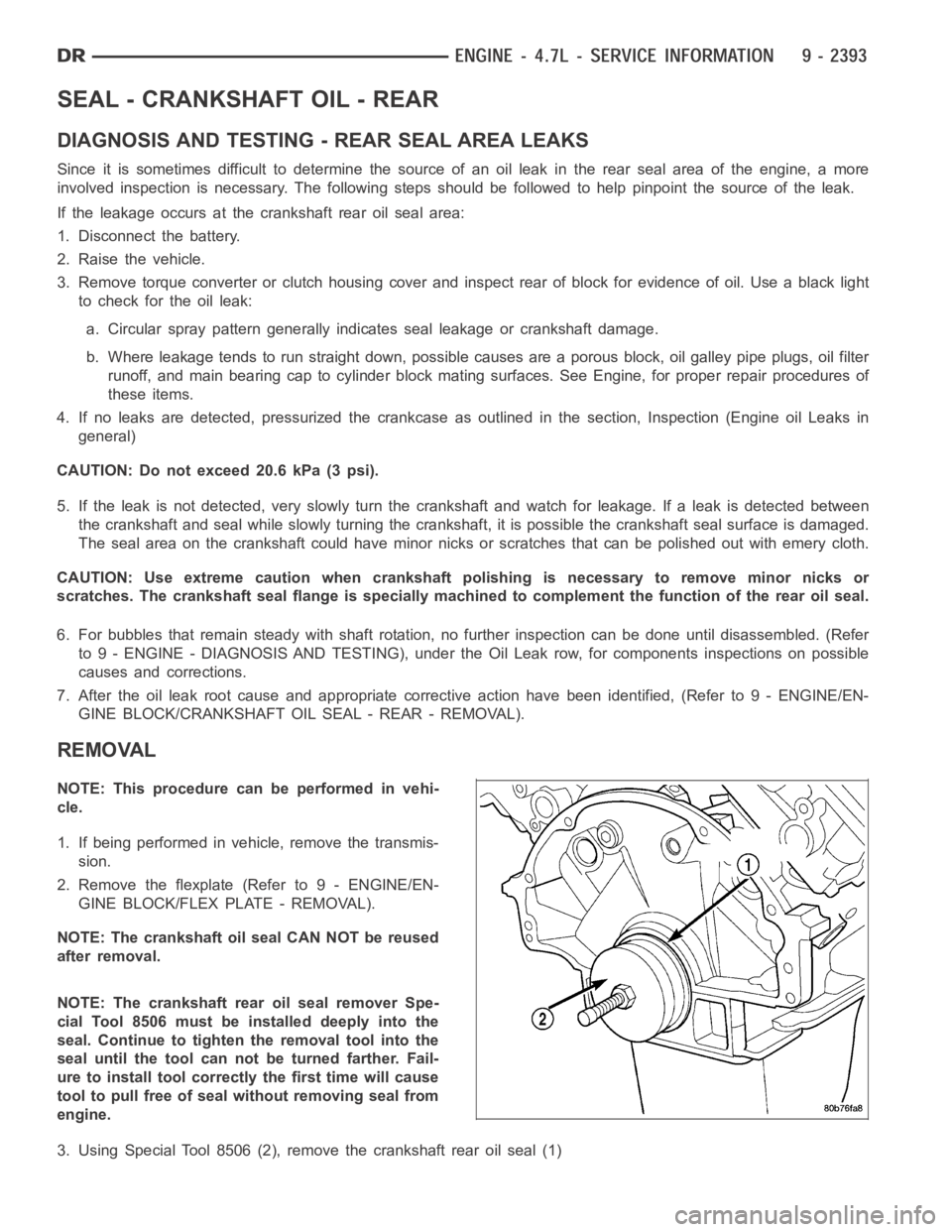
REMOVAL
NOTE: This procedure can be performed in vehi-
cle.
1. If being performed in vehicle, remove the transmis-
sion.
2. Remove the flexplate (Refer to 9 - ENGINE/EN-
GINE BLOCK/FLEX PLATE - REMOVAL).
NOTE: The crankshaft oil seal CAN NOT be reused
after removal.
NOTE: The crankshaft rear oil seal remover Spe-
cial Tool 8506 must be installed deeply into the
seal. Continue to tighten the removal tool into the
seal until the tool can not be turned farther. Fail-
ure to install tool correctly the first time will cause
tool to pull free of seal without removing seal from
engine.
3. Using Special Tool 8506 (2), remove the crankshaft rear oil seal (1)
Page 1703 of 5267
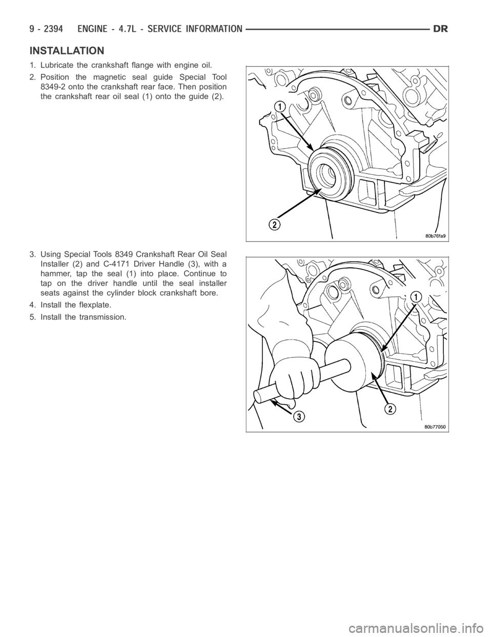
INSTALLATION
1. Lubricate the crankshaft flange with engine oil.
2. Position the magnetic seal guide Special Tool
8349-2 onto the crankshaft rear face. Then position
the crankshaft rear oil seal (1) onto the guide (2).
3. Using Special Tools 8349 Crankshaft Rear Oil Seal
Installer (2) and C-4171 Driver Handle (3), with a
hammer, tap the seal (1) into place. Continue to
tap on the driver handle until the seal installer
seats against the cylinder block crankshaft bore.
4. Install the flexplate.
5. Install the transmission.
Page 1704 of 5267
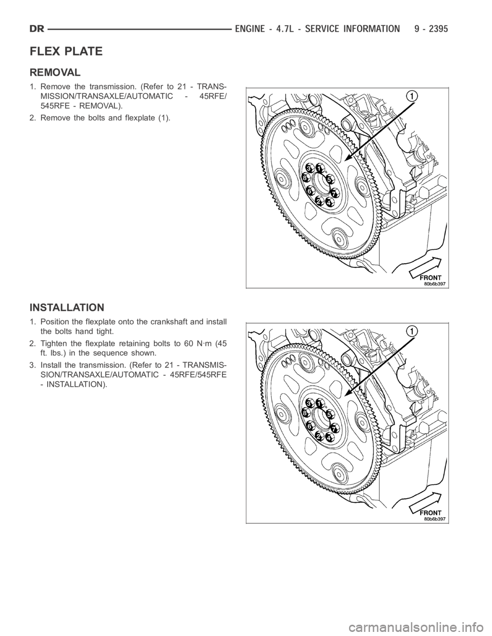
FLEX PLATE
REMOVAL
1. Remove the transmission. (Refer to 21 - TRANS-
MISSION/TRANSAXLE/AUTOMATIC - 45RFE/
545RFE - REMOVAL).
2. Remove the bolts and flexplate (1).
INSTALLATION
1. Position the flexplate ontothe crankshaft and install
the bolts hand tight.
2. Tighten the flexplate retaining bolts to 60 Nꞏm (45
ft. lbs.) in the sequence shown.
3. Install the transmission. (Refer to 21 - TRANSMIS-
SION/TRANSAXLE/AUTOMATIC - 45RFE/545RFE
- INSTALLATION).
Page 1705 of 5267
ROD - PISTON & CONNECTING
DESCRIPTION
CAUTION: Do not use a metal stamp to mark connecting rods as damage may result, instead use ink or a
scratch awl.
Thepistonsaremadeofahighstrengthaluminumalloy.Theanodizedtopring groove and crown has been
replaced with a coated top ring that is blue in color on the bottom surface. Piston skirts are coated with a solid
lubricant (Molykote) to reduce friction and provide scuff resistance. The connecting rods are made of forged pow-
dered metal, with a “fractured cap” design. A pressed fit piston pin is usedto attach the piston and connecting rod.
STANDARD PROCEDURE - PISTON FITTING
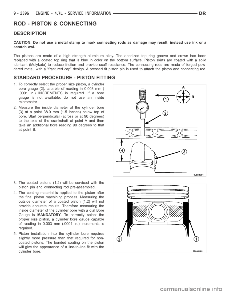
1. To correctly select the proper size piston, a cylinder
bore gauge (2), capable of reading in 0.003 mm (
.0001 in.) INCREMENTS is required. If a bore
gauge is not available, do not use an inside
micrometer.
2. Measure the inside diameter of the cylinder bore
(3) at a point 38.0 mm (1.5 inches) below top of
bore. Start perpendicular (across or at 90 degrees)
to the axis of the crankshaft at point A and then
take an additional bore reading 90 degrees to that
at point B.
3. The coated pistons (1,2) will be serviced with the
piston pin and connecting rod pre-assembled.
4. The coating material is applied to the piston after
the final piston machining process. Measuring the
outside diameter of a coated piston (1,2) will not
provide accurate results. Therefore measuring the
inside diameter of the cylinder bore with a dial Bore
Gauge isMANDATORY. To correctly select the
proper size piston, a cylinder bore gauge capable
of reading in 0.003 mm (.0001 in.) increments is
required.
5. Piston installation intothe cylinder bore requires
slightly more pressure than that required for non-
coated pistons. The bonded coating on the piston
will give the appearance of a line-to-line fit with the
cylinder bore.
Page 1706 of 5267
REMOVAL
1. Disconnect negative cable from battery.
2. Remove the following components:
Oil pan and gasket/windage tray (Refer to 9 - ENGINE/LUBRICATION/OIL PAN -REMOVAL).
Cylinder head covers (Refer to 9 - ENGINE/CYLINDER HEAD/CYLINDER HEAD COVER(S) - REMOVAL) and
(Refer to 9 - ENGINE/CYLINDER HEAD/CYLINDER HEAD COVER(S) - REMOVAL).
Timing chain cover (Refer to 9 - ENGINE/VALVE TIMING/TIMING BELT / CHAIN COVER(S) - REMOVAL).
Cylinder head(s) (Refer to 9 - ENGINE/CYLINDER HEAD - REMOVAL) and (Refer to 9 - ENGINE/CYLINDER
HEAD - REMOVAL).
3. If necessary, remove top ridge of cylinder bores with a reliable ridge reamer before removing pistons from cyl-
inder block.Be sure to keep tops of pistons covered during this operation.Pistons and connecting rods
must be removed from top of cylinder block. When removing piston and connecting rod assemblies from the
engine, rotate crankshaft so the each connecting rod is centered in cylinder bore.
CAUTION: DO NOT use a number stamp or a punch to mark connecting rods or caps,as damage to con-
necting rods could occur
NOTE: Connecting rods and bearing caps are not interchangeable and shouldbe marked before removing
to ensure correct reassembly.
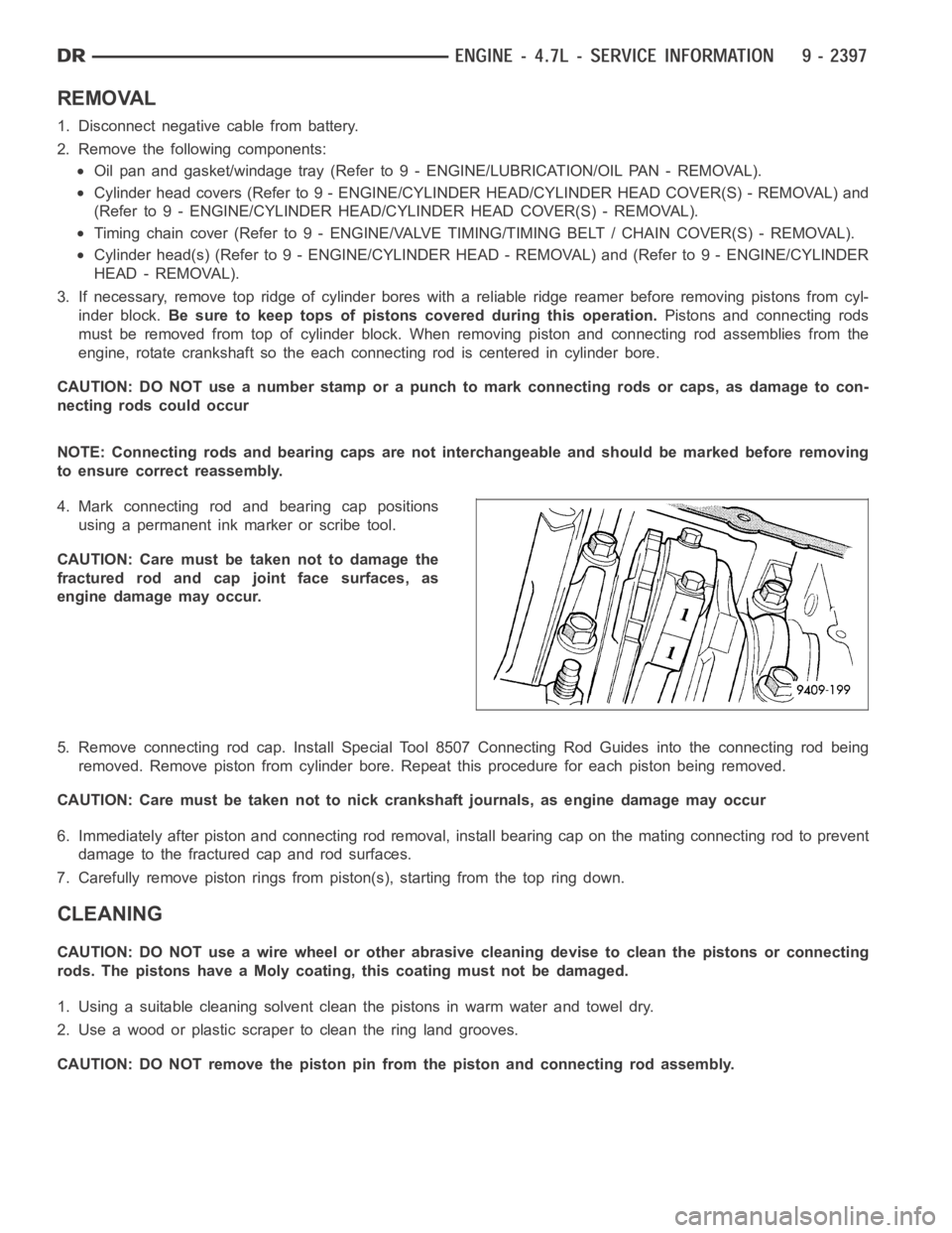
4. Mark connecting rod and bearing cap positions
using a permanent ink marker or scribe tool.
CAUTION: Care must be taken not to damage the
fractured rod and cap joint face surfaces, as
engine damage may occur.
5. Remove connecting rod cap. Install Special Tool 8507 Connecting Rod Guides into the connecting rod being
removed. Remove piston from cylinder bore. Repeat this procedure for eachpiston being removed.
CAUTION: Care must be taken not to nick crankshaft journals, as engine damage may occur
6. Immediately after piston and connecting rod removal, install bearing cap on the mating connecting rod to prevent
damage to the fractured cap and rod surfaces.
7. Carefully remove piston rings from piston(s), starting from the top ring down.
CLEANING
CAUTION: DO NOT use a wire wheel or other abrasive cleaning devise to clean the pistons or connecting
rods. The pistons have a Moly coating, this coating must not be damaged.
1. Using a suitable cleaning solvent clean the pistons in warm water and towel dry.
2. Use a wood or plastic scraper to clean the ring land grooves.
CAUTION: DO NOT remove the piston pin from the piston and connecting rod assembly.
Page 1707 of 5267
INSPECTION
Check the connecting rod journal for excessive wear, taper and scoring (Refer to 9 - ENGINE/ENGINE BLOCK/
CONNECTING ROD BEARINGS - STANDARD PROCEDURE).
Check the connecting rod for signs of twist or bending.
Check the piston for taper and elliptical shape before it is fitted into thecylinder bore (Refer to 9 - ENGINE/ENGINE
BLOCK/PISTON & CONNECTING ROD - STANDARD PROCEDURE).
Check the piston for scoring, or scraping marks in the piston skirts. Checkthe ring lands for cracks and/or deteri-
oration.
INSTALLATION
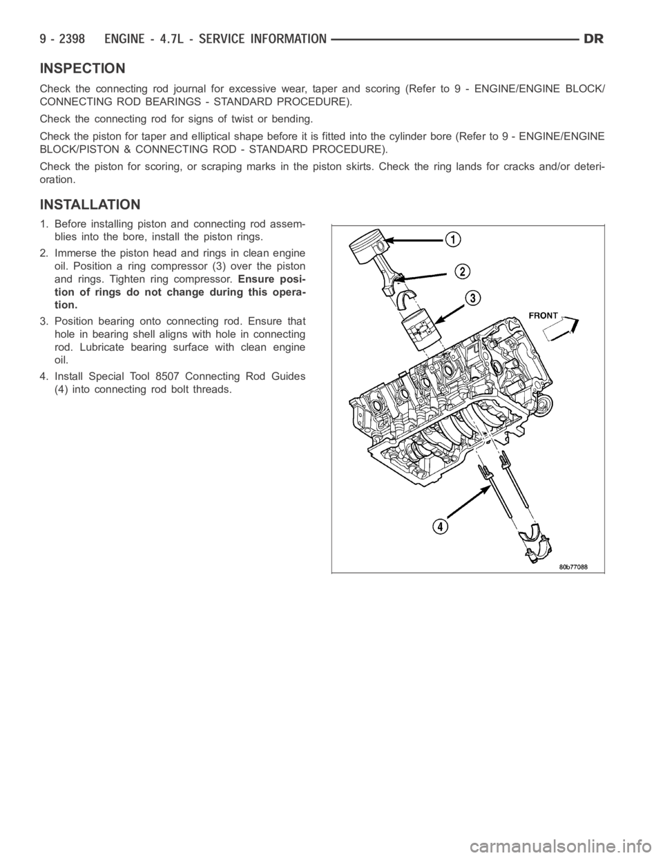
1. Before installing piston and connecting rod assem-
blies into the bore, install the piston rings.
2. Immerse the piston head and rings in clean engine
oil. Position a ring compressor (3) over the piston
and rings. Tighten ring compressor.Ensure posi-
tion of rings do not change during this opera-
tion.
3. Position bearing onto connecting rod. Ensure that
hole in bearing shell aligns with hole in connecting
rod. Lubricate bearing surface with clean engine
oil.
4. Install Special Tool 8507 Connecting Rod Guides
(4) into connecting rod bolt threads.
Page 1708 of 5267
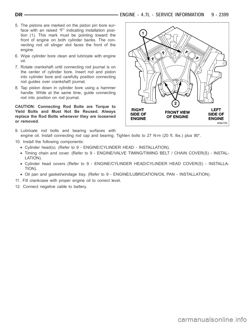
5. The pistons are marked on the piston pin bore sur-
face with an raised “F” indicating installation posi-
tion (1). This mark must be pointing toward the
front of engine on both cylinder banks. The con-
necting rod oil slinger slot faces the front of the
engine.
6. Wipe cylinder bore clean and lubricate with engine
oil.
7. Rotate crankshaft until connecting rod journal is on
the center of cylinder bore. Insert rod and piston
into cylinder bore and carefully position connecting
rod guides over crankshaft journal.
8. Tap piston down in cylinder bore using a hammer
handle. While at the same time, guide connecting
rodintopositiononrodjournal.
CAUTION: Connecting Rod Bolts are Torque to
Yield Bolts and Must Not Be Reused. Always
replace the Rod Bolts whenever they are loosened
or removed.
9. Lubricate rod bolts and bearing surfaces with
engine oil. Install connecting rod cap and bearing. Tighten bolts to 27 Nꞏm(20 ft. lbs.) plus 90°.
10. Install the following components:
Cylinder head(s). (Refer to 9 - ENGINE/CYLINDER HEAD - INSTALLATION).
Timing chain and cover. (Refer to 9 - ENGINE/VALVE TIMING/TIMING BELT / CHAIN COVER(S) - INSTAL-
LATION).
Cylinderheadcovers(Referto9-ENGINE/CYLINDER HEAD/CYLINDER HEAD COVER(S) - INSTALLA-
TION).
Oil pan and gasket/windage tray. (Refer to 9 - ENGINE/LUBRICATION/OIL PAN- INSTALLATION).
11. Fill crankcase with proper engine oil to correct level.
12. Connect negative cable to battery.
Page 1709 of 5267
RINGS - PISTON
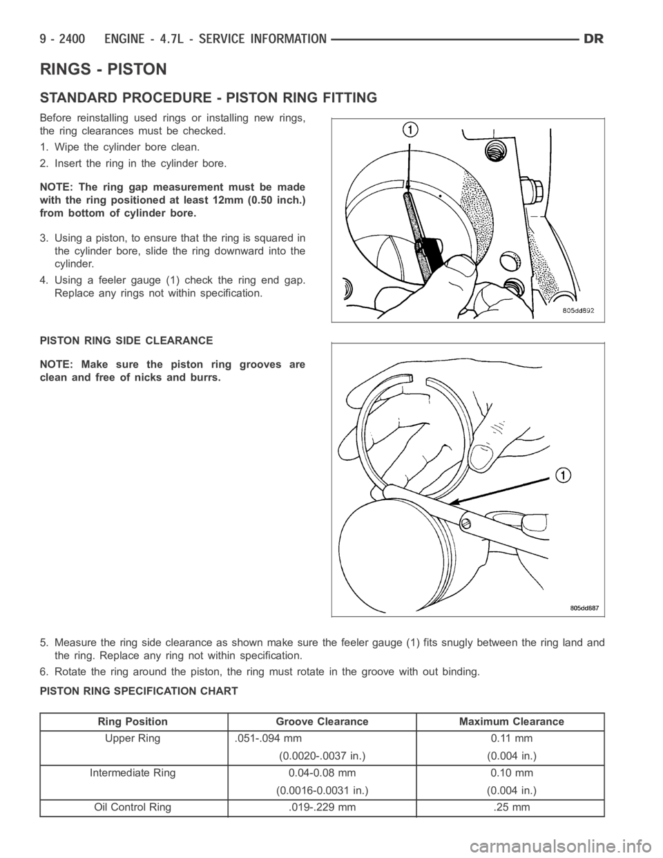
STANDARD PROCEDURE - PISTON RING FITTING
Before reinstalling used rings or installing new rings,
the ring clearances must be checked.
1. Wipe the cylinder bore clean.
2. Insert the ring in the cylinder bore.
NOTE: The ring gap measurement must be made
with the ring positioned at least 12mm (0.50 inch.)
from bottom of cylinder bore.
3. Using a piston, to ensure that the ring is squared in
the cylinder bore, slide the ring downward into the
cylinder.
4. Using a feeler gauge (1) check the ring end gap.
Replace any rings not within specification.
PISTON RING SIDE CLEARANCE
NOTE: Make sure the piston ring grooves are
clean and free of nicks and burrs.
5. Measure the ring side clearance as shown make sure the feeler gauge (1) fits snugly between the ring land and
the ring. Replace any ring not within specification.
6. Rotate the ring around the piston, the ring must rotate in the groove without binding.
PISTON RING SPECIFICATION CHART
Ring Position Groove Clearance Maximum Clearance
Upper Ring .051-.094 mm 0.11 mm
(0.0020-.0037 in.) (0.004 in.)
Intermediate Ring 0.04-0.08 mm 0.10 mm
(0.0016-0.0031 in.) (0.004 in.)
Oil Control Ring .019-.229 mm .25 mm
Page 1710 of 5267
Ring Position Groove Clearance Maximum Clearance
(Steel Rails) (.0007-.0090 in.) (0.010 in.)
Ring Position Ring Gap Wear Limit
Upper Ring 0.20-0.36 mm 0.43 mm
(0.0079-0.0142 in.) (0.0017 in.)
Intermediate Ring 0.37-0.63 mm 0.74 mm
(0.0146-0.0249 in.) (0.029 in.)
Oil Control Ring 0.025-0.76 mm 1.55 mm
(Steel Rail) (0.0099- 0.03 in.) (0.061 in.)
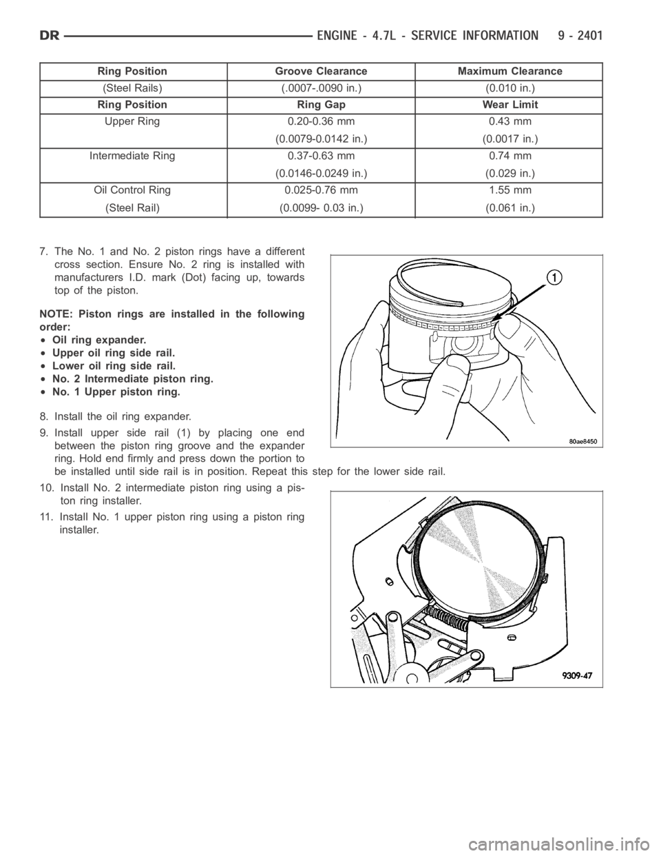
7. The No. 1 and No. 2 piston rings have a different
cross section. Ensure No. 2 ring is installed with
manufacturers I.D. mark (Dot) facing up, towards
top of the piston.
NOTE: Piston rings are installed in the following
order:
Oil ring expander.
Upper oil ring side rail.
Lower oil ring side rail.
No. 2 Intermediate piston ring.
No. 1 Upper piston ring.
8. Install the oil ring expander.
9. Install upper side rail (1) by placing one end
between the piston ring groove and the expander
ring. Hold end firmly and press down the portion to
be installed until side rail is in position. Repeat this step for the lower side rail.
10. Install No. 2 intermediate piston ring using a pis-
ton ring installer.
11. Install No. 1 upper piston ring using a piston ring
installer.