seat adjustment DODGE RAM SRT-10 2006 Service User Guide
[x] Cancel search | Manufacturer: DODGE, Model Year: 2006, Model line: RAM SRT-10, Model: DODGE RAM SRT-10 2006Pages: 5267, PDF Size: 68.7 MB
Page 2466 of 5267
DIESEL
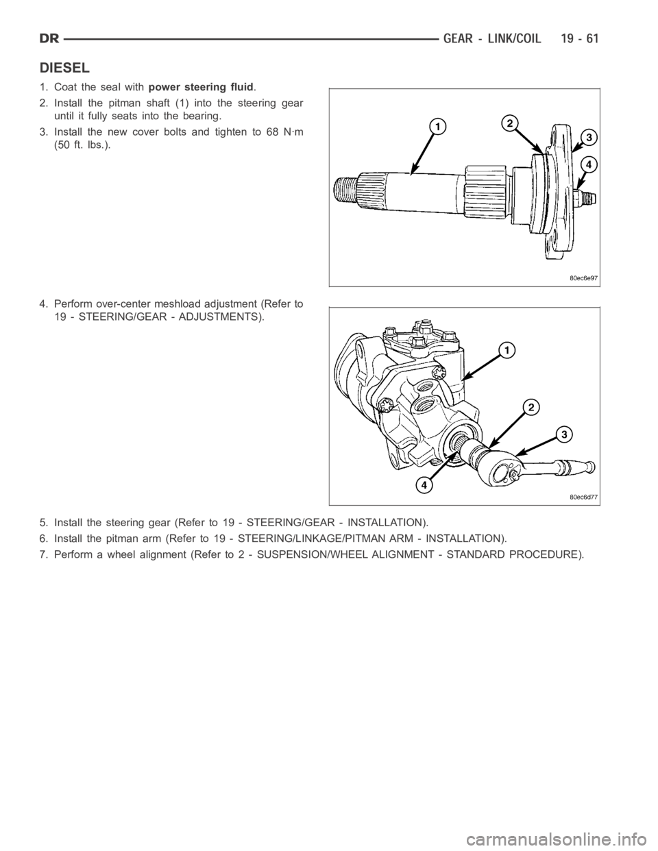
1. Coat the seal withpower steering fluid.
2. Install the pitman shaft (1) into the steering gear
until it fully seats into the bearing.
3. Install the new cover bolts and tighten to 68 Nꞏm
(50 ft. lbs.).
4. Perform over-center meshload adjustment (Refer to
19 - STEERING/GEAR - ADJUSTMENTS).
5. Install the steering gear (Refer to 19 - STEERING/GEAR - INSTALLATION).
6. Install the pitman arm (Refer to 19 - STEERING/LINKAGE/PITMAN ARM - INSTALLATION).
7. Perform a wheel alignment (Refer to 2- SUSPENSION/WHEEL ALIGNMENT - STANDARD PROCEDURE).
Page 2583 of 5267
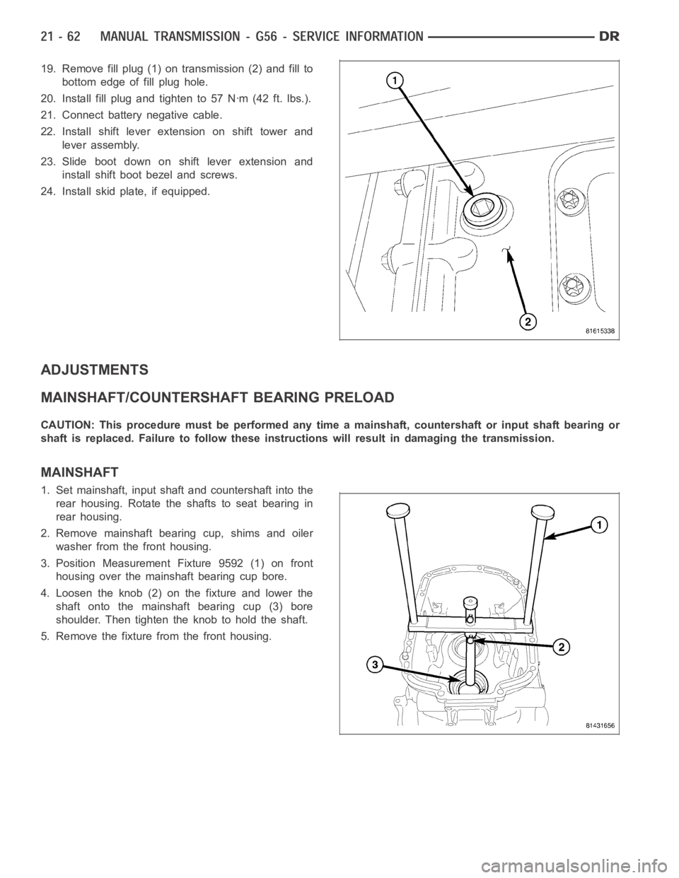
19. Remove fill plug (1) on transmission (2) and fill to
bottom edge of fill plug hole.
20. Install fill plug and tighten to 57 Nꞏm (42 ft. lbs.).
21. Connect battery negative cable.
22. Install shift lever extension on shift tower and
lever assembly.
23. Slide boot down on shift lever extension and
install shift boot bezel and screws.
24. Install skid plate, if equipped.
ADJUSTMENTS
MAINSHAFT/COUNTERSHAFT BEARING PRELOAD
CAUTION: This procedure must be performed any time a mainshaft, countershaft or input shaft bearing or
shaft is replaced. Failure to follow these instructions will result in damaging the transmission.
MAINSHAFT
1. Set mainshaft, input shaft and countershaft into the
rear housing. Rotate the shafts to seat bearing in
rear housing.
2. Remove mainshaft bearing cup, shims and oiler
washer from the front housing.
3. Position Measurement Fixture 9592 (1) on front
housing over the mainshaft bearing cup bore.
4. Loosen the knob (2) on the fixture and lower the
shaft onto the mainshaft bearing cup (3) bore
shoulder. Then tighten the knob to hold the shaft.
5. Remove the fixture from the front housing.
Page 2712 of 5267
ADJUSTMENTS
ADUSTMENTS
MAINSHAFT BEARINGS PRELOAD
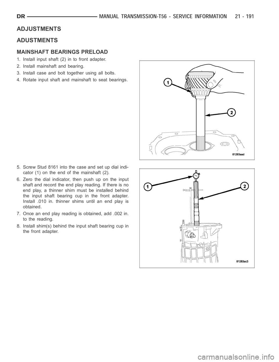
1. Install input shaft (2) in to front adapter.
2. Install mainshaft and bearing.
3. Install case and bolt together using all bolts.
4. Rotate input shaft and mainshaft to seat bearings.
5. Screw Stud 8161 into the case and set up dial indi-
cator (1) on the end of the mainshaft (2).
6. Zerothedialindicator,thenpushupontheinput
shaft and record the end play reading. If there is no
end play, a thinner shim must be installed behind
the input shaft bearing cup in the front adapter.
Install .010 in. thinner shims until an end play is
obtained.
7. Once an end play reading is obtained, add .002 in.
to the reading.
8. Install shim(s) behind the input shaft bearing cup in
the front adapter.
Page 2961 of 5267
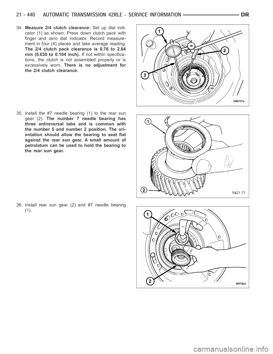
34.Measure 2/4 clutch clearance:Set up dial indi-
cator (1) as shown. Press down clutch pack with
finger and zero dial indicator. Record measure-
ment in four (4) places and take average reading.
The 2/4 clutch pack clearance is 0.76 to 2.64
mm (0.030 to 0.104 inch).If not within specifica-
tions, the clutch is not assembled properly or is
excessively worn.There is no adjustment for
the 2/4 clutch clearance.
35. Install the #7 needle bearing (1) to the rear sun
gear (2).The number 7 needle bearing has
three antireversal tabs and is common with
the number 5 and number 2 position. The ori-
entation should allow the bearing to seat flat
against the rear sun gear. A small amount of
petrolatum can be used to hold the bearing to
the rear sun gear.
36. Install rear sun gear (2) and #7 needle bearing
(1).
Page 2968 of 5267
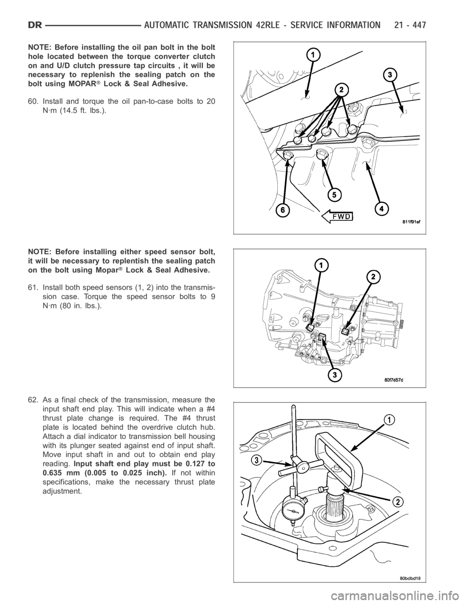
NOTE: Before installing the oil pan bolt in the bolt
hole located between the torque converter clutch
on and U/D clutch pressure tap circuits , it will be
necessary to replenish the sealing patch on the
bolt using MOPAR
Lock & Seal Adhesive.
60. Install and torque the oil pan-to-case bolts to 20
Nꞏm (14.5 ft. lbs.).
NOTE: Before installing either speed sensor bolt,
it will be necessary to replentish the sealing patch
on the bolt using Mopar
Lock & Seal Adhesive.
61. Install both speed sensors (1, 2) into the transmis-
sion case. Torque the speed sensor bolts to 9
Nꞏm (80 in. lbs.).
62. As a final check of the transmission, measure the
input shaft end play. This will indicate when a #4
thrust plate change is required. The #4 thrust
plate is located behind the overdrive clutch hub.
Attach a dial indicator to transmission bell housing
with its plunger seated against end of input shaft.
Move input shaft in and out to obtain end play
reading.Input shaft end play must be 0.127 to
0.635 mm (0.005 to 0.025 inch).If not within
specifications, make the necessary thrust plate
adjustment.
Page 3009 of 5267
BEARINGS
ADJUSTMENTS
BEARING ADJUSTMENT PROCEDURES
Take extreme care when removing andinstalling bearing cups and cones.Use only an arbor press for installa-
tion,as a hammer may not properly align the bearing cup or cone. Burrs or nicks on the bearing seat will give a
false end play reading, while gauging for proper shims. Improperly seatedbearing cup and cones are subject to
low-mileage failure.
Bearing cups and cones should be replaced if they show signs of pitting or heat distress.
If distress is seen on either the cup or bearing rollers, both cup and cone must be replaced.
NOTE: Bearing drag torque specifications must be maintained to avoid premature bearing failures.
Used (original) bearing may lose up to 50 percent of the original drag torque after break-in.
NOTE: All bearing adjustments must be made with no other component interference or gear inter-mesh.
Oil all bearings before checking turning torque.
Page 3018 of 5267
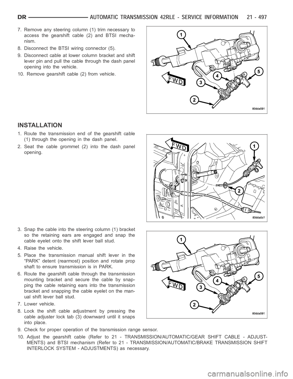
7. Remove any steering column (1) trim necessary to
access the gearshift cable (2) and BTSI mecha-
nism.
8. Disconnect the BTSI wiring connector (5).
9. Disconnect cable at lower column bracket and shift
lever pin and pull the cable through the dash panel
opening into the vehicle.
10. Remove gearshift cable (2) from vehicle.
INSTALLATION
1. Route the transmission end of the gearshift cable
(1) through the opening in the dash panel.
2. Seat the cable grommet (2) into the dash panel
opening.
3. Snap the cable into the steering column (1) bracket
so the retaining ears are engaged and snap the
cable eyelet onto the shift lever ball stud.
4. Raise the vehicle.
5. Place the transmission manual shift lever in the
“PARK” detent (rearmost) position and rotate prop
shaft to ensure transmission is in PARK.
6. Route the gearshift cable through the transmission
mounting bracket and secure the cable by snap-
ping the cable retaining ears into the transmission
bracket and snapping the cable eyelet on the man-
ual shift lever ball stud.
7. Lower vehicle.
8. Lock the shift cable adjustment by pressing the
cable adjuster lock tab (3) downward until it snaps
into place.
9. Check for proper operation of the transmission range sensor.
10. Adjust the gearshift cable (Refer to 21 - TRANSMISSION/AUTOMATIC/GEAR SHIFT CABLE - ADJUST-
MENTS) and BTSI mechanism (Refer to 21 - TRANSMISSION/AUTOMATIC/BRAKE TRANSMISSION SHIFT
INTERLOCK SYSTEM - ADJUSTMENTS) as necessary.
Page 3435 of 5267
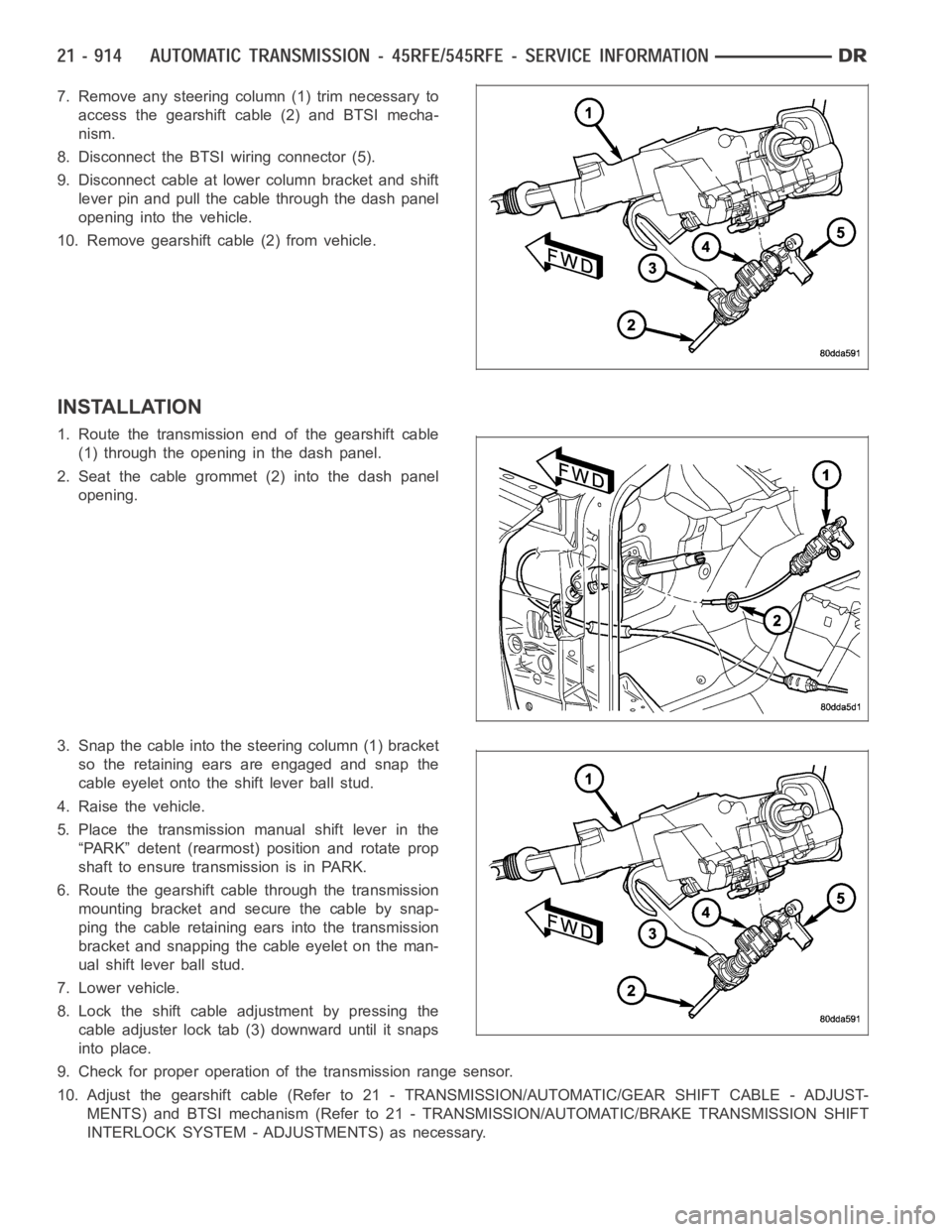
7. Remove any steering column (1) trim necessary to
access the gearshift cable (2) and BTSI mecha-
nism.
8. Disconnect the BTSI wiring connector (5).
9. Disconnect cable at lower column bracket and shift
lever pin and pull the cable through the dash panel
opening into the vehicle.
10. Remove gearshift cable (2) from vehicle.
INSTALLATION
1. Route the transmission end of the gearshift cable
(1) through the opening in the dash panel.
2. Seat the cable grommet (2) into the dash panel
opening.
3. Snap the cable into the steering column (1) bracket
so the retaining ears are engaged and snap the
cable eyelet onto the shift lever ball stud.
4. Raise the vehicle.
5. Place the transmission manual shift lever in the
“PARK” detent (rearmost) position and rotate prop
shaft to ensure transmission is in PARK.
6. Route the gearshift cable through the transmission
mounting bracket and secure the cable by snap-
ping the cable retaining ears into the transmission
bracket and snapping the cable eyelet on the man-
ual shift lever ball stud.
7. Lower vehicle.
8. Lock the shift cable adjustment by pressing the
cable adjuster lock tab (3) downward until it snaps
into place.
9. Check for proper operation of the transmission range sensor.
10. Adjust the gearshift cable (Refer to 21 - TRANSMISSION/AUTOMATIC/GEAR SHIFT CABLE - ADJUST-
MENTS) and BTSI mechanism (Refer to 21 - TRANSMISSION/AUTOMATIC/BRAKE TRANSMISSION SHIFT
INTERLOCK SYSTEM - ADJUSTMENTS) as necessary.
Page 3837 of 5267
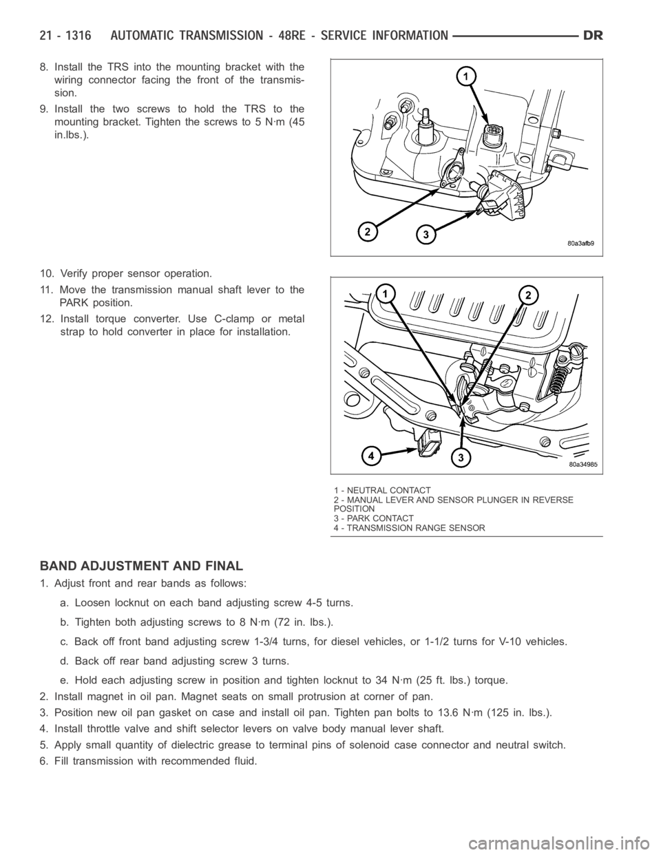
8. Install the TRS into the mounting bracket with the
wiring connector facing the front of the transmis-
sion.
9. Install the two screws to hold the TRS to the
mounting bracket. Tighten the screws to 5 Nꞏm (45
in.lbs.).
10. Verify proper sensor operation.
11. Move the transmission manual shaft lever to the
PARK position.
12. Install torque converter. Use C-clamp or metal
strap to hold converter in place for installation.
BAND ADJUSTMENT AND FINAL
1. Adjust front and rear bands as follows:
a. Loosen locknut on each band adjusting screw 4-5 turns.
b. Tighten both adjusting screws to 8 Nꞏm (72 in. lbs.).
c. Back off front band adjusting screw 1-3/4 turns, for diesel vehicles, or1-1/2 turns for V-10 vehicles.
d. Back off rear band adjusting screw 3 turns.
e. Hold each adjusting screw in position and tighten locknut to 34 Nꞏm (25 ft. lbs.) torque.
2. Install magnet in oil pan. Magnet seats on small protrusion at corner of pan.
3. Position new oil pan gasket on case and install oil pan. Tighten pan boltsto 13.6 Nꞏm (125 in. lbs.).
4. Install throttle valve and shift selector levers on valve body manual lever shaft.
5. Apply small quantity of dielectric grease to terminal pins of solenoid case connector and neutral switch.
6. Fill transmission with recommended fluid.
1 - NEUTRAL CONTACT
2 - MANUAL LEVER AND SENSOR PLUNGER IN REVERSE
POSITION
3 - PARK CONTACT
4 - TRANSMISSION RANGE SENSOR
Page 3888 of 5267
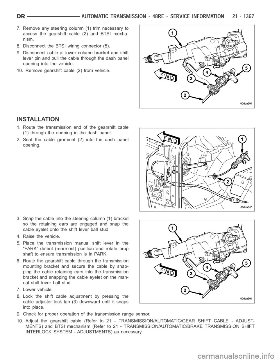
7. Remove any steering column (1) trim necessary to
access the gearshift cable (2) and BTSI mecha-
nism.
8. Disconnect the BTSI wiring connector (5).
9. Disconnect cable at lower column bracket and shift
lever pin and pull the cable through the dash panel
opening into the vehicle.
10. Remove gearshift cable (2) from vehicle.
INSTALLATION
1. Route the transmission end of the gearshift cable
(1) through the opening in the dash panel.
2. Seat the cable grommet (2) into the dash panel
opening.
3. Snap the cable into the steering column (1) bracket
so the retaining ears are engaged and snap the
cable eyelet onto the shift lever ball stud.
4. Raise the vehicle.
5. Place the transmission manual shift lever in the
“PARK” detent (rearmost) position and rotate prop
shaft to ensure transmission is in PARK.
6. Route the gearshift cable through the transmission
mounting bracket and secure the cable by snap-
ping the cable retaining ears into the transmission
bracket and snapping the cable eyelet on the man-
ual shift lever ball stud.
7. Lower vehicle.
8. Lock the shift cable adjustment by pressing the
cable adjuster lock tab (3) downward until it snaps
into place.
9. Check for proper operation of the transmission range sensor.
10. Adjust the gearshift cable (Refer to 21 - TRANSMISSION/AUTOMATIC/GEAR SHIFT CABLE - ADJUST-
MENTS) and BTSI mechanism (Refer to 21 - TRANSMISSION/AUTOMATIC/BRAKE TRANSMISSION SHIFT
INTERLOCK SYSTEM - ADJUSTMENTS) as necessary.