stop start DODGE RAM SRT-10 2006 Service Repair Manual
[x] Cancel search | Manufacturer: DODGE, Model Year: 2006, Model line: RAM SRT-10, Model: DODGE RAM SRT-10 2006Pages: 5267, PDF Size: 68.7 MB
Page 221 of 5267

P2115-ACCELERATOR PEDAL POSITION SENSOR 1 MINIMUM STOP
PERFORMANCE
For a complete wiring diagramRefer to Section 8W.
When Monitored:
Ignition on. During in plant mode the APP Sensors need to be checked to make sure that idle and full pedal
travel can be reached on both sensors. The test for P2115 is only enabled once test for P2166 has passed.
Set Condition:
APPS No.1 has failed to achieve the required minimum value during In Plant testing. One trip fault and the
code will set within 5 seconds. Engine will only idle.
Possible Causes
IN PLANT TEST FAILURE
APPS RELEARN
Always perform the Pre-Diagnostic Troubleshooting procedure before proceeding. (Refer to 9 - ENGINE -
DIAGNOSIS AND TESTING).
Diagnostic Test
1.IN PLANT TEST FAILURE
Ignition on, engine not running.
NOTE: This DTC is set when the APP Sensors are learned in plant but do not reach the Minimum or Max-
imum voltage range.
With a scan tool read DTCs.
With the scan tool, erase DTCs.
Start the engine.
With the scan tool, read DTCs.
NOTE: Diagnose any APPS out of Range and 5-Volt Supply DTCs before continuing.
Is the DTC active at this time?
Ye s>>
Go To 2
No>>
Refer to the INTERMITTENT CONDITION Diagnostic Procedure.
Perform the POWERTRAIN VERIFICATION TEST. (Refer to 9 - ENGINE - STANDARD PROCEDURE)
2.APPS RELEARN
With a scan tool select the ETC RELEARN function.
Next, erase DTCs.
Start the engine.
Does the DTC return?
Ye s>>
Replace the APPS Assembly per Service Information. After installation iscomplete, use a scan tool and
select the ETC RELEARN function.
Perform the POWERTRAIN VERIFICATION TEST. (Refer to 9 - ENGINE - STANDARD PROCEDURE)
No>>
Te s t C o m p l e t e .
Page 222 of 5267
P2116-ACCELERATOR PEDAL POSITION SENSOR 2 MINIMUM STOP
PERFORMANCE
For a complete wiring diagramRefer to Section 8W.
When Monitored:
Ignition on. During in plant mode the APP Sensors need to be checked to make sure that idle and full pedal
travel can be reached on both sensors. The test for P2116 is only enabled once test for P2167 has passed.
Set Condition:
APPS No.2 has failed to achieve the required minimum value during In Plant testing. One trip fault and the
code will be stored within 5 seconds. Engine will only idle.
Possible Causes
IN PLANT TEST FAILURE
APPS RELEARN
Always perform the Pre-Diagnostic Troubleshooting procedure before proceeding. (Refer to 9 - ENGINE -
DIAGNOSIS AND TESTING).
Diagnostic Test
1.IN PLANT TEST FAILURE
Ignition on, engine not running.
NOTE: This DTC is set when the APP Sensors are learned in plant but do not reach the Minimum or Max-
imum voltage range.
With a scan tool read DTCs and record the related Freeze Frame data.
With a scan tool, erase DTCs.
Start the engine.
With a scan tool, read DTCs.
Is the DTC active at this time?
Ye s>>
Go To 2
No>>
Refer to the INTERMITTENT CONDITION Diagnostic Procedure.
Perform the POWERTRAIN VERIFICATION TEST. (Refer to 9 - ENGINE - STANDARD PROCEDURE)
2.APPS RELEARN
With a scan tool select the ETC RELEARN function.
Next, erase DTCs.
Start the engine.
Does the DTC return?
Ye s>>
Replace the APPS Assembly per Service Information. After installation iscomplete, use a scan tool and
select the ETC RELEARN function.
Perform the POWERTRAIN VERIFICATION TEST. (Refer to 9 - ENGINE - STANDARD PROCEDURE)
No>>
Te s t C o m p l e t e .
Page 267 of 5267
P2166-ACCELERATOR PEDAL POSITION SENSOR 1 MAXIMUM STOP
PERFORMANCE
For a complete wiring diagramRefer to Section 8W.
When Monitored:
Ignition on. During in plant mode the APP Sensors need to be checked to make sure that idle and full pedal
travelcanbereachedonbothsensors.
Set Condition:
APPS No.1 has failed to achieve the required maximum value during In Plant testing. One trip fault and the
code will set within 5 seconds. Engine will only idle.
Possible Causes
IN PLANT TEST FAILURE
APPS RELEARN
Always perform the Pre-Diagnostic Troubleshooting procedure before proceeding. (Refer to 9 - ENGINE -
DIAGNOSIS AND TESTING).
Diagnostic Test
1.IN PLANT TEST FAILURE
Ignition on, engine not running.
NOTE: This DTC is set when the APP Sensors are learned in plant but do not reach the Minimum or Max-
imum voltage range.
With a scan tool read DTCs.
With the scan tool, erase DTCs.
Start the engine.
With the scan tool, read DTCs.
Is the DTC active at this time?
Ye s>>
Go To 2
No>>
Refer to the INTERMITTENT CONDITION Diagnostic Procedure.
Perform the POWERTRAIN VERIFICATION TEST. (Refer to 9 - ENGINE - STANDARD PROCEDURE)
2.APPS RELEARN
With a scan tool select the ETC RELEARN function.
Next, erase DTCs.
Start the engine.
Does the DTC return?
Ye s>>
Replace the APPS Assembly per Service Information. After installation iscomplete, use a scan tool and
select the ETC RELEARN function.
Perform the POWERTRAIN VERIFICATION TEST. (Refer to 9 - ENGINE - STANDARD PROCEDURE)
No>>
Te s t C o m p l e t e .
Page 268 of 5267
P2167-ACCELERATOR PEDAL POSITION SENSOR 2 MAXIMUM STOP
PERFORMANCE
For a complete wiring diagramRefer to Section 8W.
When Monitored:
Ignition on. During in plant mode the APP Sensors need to be checked to make sure that idle and full pedal
travelcanbereachedonbothsensors.
Set Condition:
APPS No.2 has failed to achieve the required maximum value during In Plant testing. One trip fault and the
code will set within 5 seconds. Engine will only idle.
Possible Causes
IN PLANT TEST FAILURE
APPS RELEARN
Diagnostic Test
1.IN PLANT TEST FAILURE
Ignition on, engine not running.
NOTE: This DTC is set when the APP Sensors are learned in plant but do not reach the Minimum or Max-
imum voltage range.
With a scan tool read DTCs.
With the scan tool, erase DTCs.
Start the engine.
With the scan tool, read DTCs.
Is the DTC active at this time?
Ye s>>
Go To 2
No>>
Refer to the INTERMITTENT CONDITION Diagnostic Procedure.
Perform the POWERTRAIN VERIFICATION TEST. (Refer to 9 - ENGINE - STANDARD PROCEDURE)
2.APPS RELEARN
With a scan tool select the ETC RELEARN function.
Next, erase DTCs.
Start the engine.
Does the DTC return?
Ye s>>
Replace the APPS Assembly per Service Information. After installation iscomplete, use a scan tool and
select the ETC RELEARN function.
Perform the POWERTRAIN VERIFICATION TEST. (Refer to 9 - ENGINE - STANDARD PROCEDURE)
No>>
Te s t C o m p l e t e .
Page 317 of 5267
3.APP SENSOR SWEEP
Ignition on, engine not running.
With a scan tool, monitor both APP Sensor voltage readings.
Slowly press the accelerator pedal from idle until it reaches the end stop near the floor.
APPS No.1 voltage should start at approximately 0.45 of a volt and increaseto approximately 4.6 volts with a
smooth transition.
APPS No.2 voltage should start at approximately 0.22 of a volt and increaseto approximately 2.31 volts with a
smooth transition.
Does the voltage for the appropriate sensor follow the list specification?
Ye s>>
Refer to the INTERMITTENT CONDITION Diagnostic Procedure.
Perform the POWERTRAIN VERIFICATION TEST. (Refer to 9 - ENGINE - STANDARD PROCEDURE)
No>>
Check the Signal and Return circuits for opens and shorts. If OK, Replace the APP Sensor Assembly
per Service Information. After installation is complete, with a scan toolselect the ETC RELEARN func-
tion to relearn the APPS values.
Perform the POWERTRAIN VERIFICATION TEST. (Refer to 9 - ENGINE - STANDARD PROCEDURE)
Page 449 of 5267
4.TP SENSOR NO.1 VOLTAGE GREATER THAN0.92 VOLTS WITH THROTTLE CLOSED
With the scan tool, read Throttle Position Sensor No.1 voltage.
Throttle must be against its stop.
Is the voltage 0.92 or less with the Throttle closed?
Ye s>>
Go To 5
No>>
Check for a binding throttle condition. If OK, replace the Throttle Position Sensor or the Throttle Body
Assemblyona5.7L.
Perform the POWERTRAIN VERIFICATION TEST. (Refer to 9 - ENGINE - STANDARD PROCEDURE)
5.ECT SENSOR OPERATION
NOTE: For this test to be valid, the thermostat must be operating correctly.
NOTE: This test works best if performed on a cold engine (cold soaked).
NOTE: If the vehicle was allowed to sit over night with no engine start, coolant temperature should be near
ambient temperatures.
Ignition on, engine not running.
With the scan tool, read the ECT value.
NOTE: If engine coolant temperature is above 82° C (180° F), allow the engine to cool until 65° C (150° F) is
reached.
Start the engine.
During engine warm-up, monitor the Engine Coolant Temperature value. Thetemperature value change should be a
smooth transition from start up to normal operating temp 82° C (180° F). Thevalue should reach at least 82° C
(180° F).
Did the Engine Temperature value increase smoothly and did it reach at least 82° C (180° F)?
Ye s>>
Go To 6
No>>
Replace the Engine Coolant Temperature Sensor.
Perform the POWERTRAIN VERIFICATION TEST. (Refer to 9 - ENGINE - STANDARD PROCEDURE)
6.OTHER POSSIBLE CAUSES OF START AND STALL CONDITION
The following additional items should be checked as a possible cause for a start and stall condition.
Refer to any Technical Service Bulletins (TSBs) that may apply to the symptom.
The exhaust system must be free of any restrictions.
The engine compression must be within specifications.
The engine valve timing must be within specifications.
Theenginemustbefreefromvacuumleaks.
The throttle body must be free of carbon buildup and dirt.
Do any of the above conditions exist?
Ye s>>
Repair as necessary.
Perform the POWERTRAIN VERIFICATION TEST. (Refer to 9 - ENGINE - STANDARD PROCEDURE)
No>>
Go To 7
Page 462 of 5267
POWERTRAIN VERIFICATION TEST VER - 2 (DIESEL)
Diagnostic Test
1.POWERTRAIN VERIFICATION TEST VER - 2 (DIESEL)
1. Check if any of the following conditions exist.
2. The ECM has been disconnected or replace.
3. The Battery power has been disconnected.
4. If the PCM has been replaced, do the following:
NOTE: 5. If the Engine Control Module has been changed and the correct VIN and mileage have not been
programmed, a DTC will be set in the ABS and Airbag Module.
6. For ABS and Airbag Systems: Enter correct VIN and Mileage in the ECM. Erase ABS and Airbag Module codes.
7. If the ECM has been replaced, do the following.
8. If this verification procedure is being performed after a No Trouble Code repair, do the following.
9. Check to see if the initial symptom still exists. If the initial or another symptom exists, the repair is not complete.
Check all pertinent Technical Service Bulletins and return to the Symptomlist if necessary.
10. If this verification procedure is being performed after a Trouble Coderepair, do the following.
11. Connect the scan tool to the data link connector and erase trouble codes.
12. With the scan tool, reset all memory values.
13. If this test is for an A/C trouble code, ensure it is operating during thefollowing road test.
14. Drive the vehicle for at least five minutes, For some of the drive, go at least 64 km/h (40 MPH). At some point
stop the vehicle and turn the engine off for 10 seconds or more; then restartand continue. Ensure the transmission
shifts through all gears.
15. Upon completion of the road test, turn the engine off and read trouble codeswiththescantool.Ifatroublecode
has been set, return to the Symptom list and follow the path specified.
Is there any DTC(s) present?
Ye s>>
Repair is not complete, refer to appropriate symptom.
No>>
Repair is complete.
Page 998 of 5267
When Monitored:
With ECT greater than 147°F, after reaching a vehicle speed of 10 mph, and the throttle remaining open (off
idle) for 2 minutes, bring the vehicle to a stop and allow the engine to idle with the transmission in DRIVE.
Set Condition:
The oxygen sensor signal voltage is switching from below 0.27 of a volt to above 0.62 of a volt and back fewer
times than required.
Possible Causes
EXHAUST LEAK
(K41) O2 1/1 SIGNAL CIRCUIT
(K900) SENSOR GROUND CIRCUIT
O2 SENSOR
Always perform the Pre-Diagnostic Troubleshooting procedure before proceeding. (Refer to 9 - ENGINE -
DIAGNOSIS AND TESTING).
Diagnostic Test
1.ACTIVE DTC
NOTE: Check for contaminants that may have damaged the O2 Sensor: contaminated fuel, unapproved sil-
icone, oil and coolant.
Ignition on, engine not running.
NOTE: After the repairs have been made, verify proper O2 Sensor operation.If all the O2 Sensor voltage
readings have not returned to normal, follow the diagnostic procedure forthe remaining O2 Sensors.
With a scan tool, read DTCs.
Is the DTC active at this time?
Ye s>>
Go To 2
No>>
Refer to the INTERMITTENT CONDITION Symptom. (Refer to 9 - ENGINE - DIAGNOSIS AND TEST-
ING)
2.EXHAUST LEAK
Start the engine.
Inspect the exhaust system for leaks between the engine and the O2 Sensors.
Are there any exhaust leaks?
Ye s>>
Repair or replace the leaking exhaust parts as necessary.
Perform the POWERTRAIN VERIFICATION TEST. (Refer to 9 - ENGINE - STANDARD PROCEDURE)
No>>
Go To 3
3.(K41) O2 1/1 SIGNAL CIRCUIT VOLTAGE DROP
Turn the ignition off.
While backprobing, measure the voltage of the (K41) O2 Sensor 1/1 Signal circuit between the 1/1 O2 Sensor har-
ness connector and PCM harness connector.
NOTE: Make sure the voltmeter leads meet the terminals in the connector andthat there is good terminal to
wire connection and are connected for positive polarity.
Start the engine.
Page 1031 of 5267
When Monitored:
With ECT greater than 147°F, after reaching a vehicle speed of 10 mph, and the throttle remaining open (off
idle) for 2 minutes, bring the vehicle to a stop and allow the engine to idle with the transmission in DRIVE.
Set Condition:
The oxygen sensor signal voltage is switching from below 0.27 of a volt to above 0.62 of a volt and back fewer
times than required.
Possible Causes
EXHAUST LEAK
(K43) O2 2/1 SIGNAL CIRCUIT
(K900) SENSOR GROUND CIRCUIT
O2 SENSOR
Always perform the Pre-Diagnostic Troubleshooting procedure before proceeding. (Refer to 9 - ENGINE -
DIAGNOSIS AND TESTING).
Diagnostic Test
1.ACTIVE DTC
NOTE: Check for contaminants that may have damaged the O2 Sensor: contaminated fuel, unapproved sil-
icone, oil and coolant.
Ignition on, engine not running.
NOTE: After the repairs have been made, verify proper O2 Sensor operation.If all the O2 Sensor voltage
readings have not returned to normal, follow the diagnostic procedure forthe remaining O2 Sensors.
With a scan tool, read DTCs and record the related Freeze Frame data.
Is the DTC active at this time?
Ye s>>
Go To 2
No>>
Refer to the INTERMITTENT CONDITION Diagnostic Procedure. (Refer to 9 - ENGINE - STANDARD
PROCEDURE)
2.EXHAUST LEAK
Start the engine.
Inspect the exhaust system for leaks between the engine and the O2 Sensors.
Are there any exhaust leaks?
Ye s>>
Repair or replace the leaking exhaust parts as necessary.
Perform the POWERTRAIN VERIFICATION TEST. (Refer to 9 - ENGINE - STANDARD PROCEDURE)
No>>
Go To 3
3.(K43) O2 2/1 SIGNAL CIRCUIT VOLTAGE DROP
Turn the ignition off.
While backprobing, measure the voltage of the (K43) O2 Sensor 2/1 Signal circuit between the 2/1 O2 Sensor har-
ness connector and PCM harness connector.
NOTE: Make sure the voltmeter leads meet the terminals in the connector andthat there is good terminal to
wire connection and are connected for positive polarity.
Start the engine.
Page 1062 of 5267
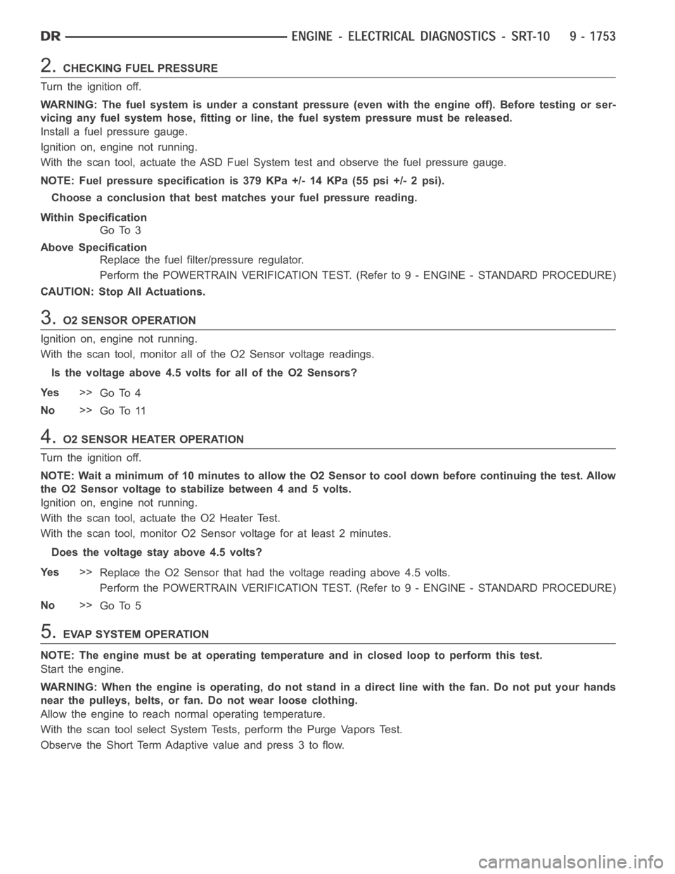
2.CHECKING FUEL PRESSURE
Turn the ignition off.
WARNING: The fuel system is under a constant pressure (even with the engineoff). Before testing or ser-
vicing any fuel system hose, fitting or line, the fuel system pressure mustbe released.
Install a fuel pressure gauge.
Ignition on, engine not running.
With the scan tool, actuate the ASD FuelSystem test and observe the fuel pressure gauge.
NOTE: Fuel pressure specification is 379 KPa +/- 14 KPa (55 psi +/- 2 psi).
Choose a conclusion that best matches your fuel pressure reading.
Within Specification
Go To 3
Above Specification
Replace the fuel filter/pressure regulator.
Perform the POWERTRAIN VERIFICATION TEST. (Refer to 9 - ENGINE - STANDARD PROCEDURE)
CAUTION: Stop All Actuations.
3.O2 SENSOR OPERATION
Ignition on, engine not running.
With the scan tool, monitor all of the O2 Sensor voltage readings.
Is the voltage above 4.5 volts for all of the O2 Sensors?
Ye s>>
Go To 4
No>>
Go To 11
4.O2 SENSOR HEATER OPERATION
Turn the ignition off.
NOTE: Wait a minimum of 10 minutes to allow the O2 Sensor to cool down before continuing the test. Allow
the O2 Sensor voltage to stabilize between 4 and 5 volts.
Ignition on, engine not running.
With the scan tool, actuate the O2 Heater Test.
With the scan tool, monitor O2 Sensor voltage for at least 2 minutes.
Does the voltage stay above 4.5 volts?
Ye s>>
Replace the O2 Sensor that had the voltage reading above 4.5 volts.
Perform the POWERTRAIN VERIFICATION TEST. (Refer to 9 - ENGINE - STANDARD PROCEDURE)
No>>
Go To 5
5.EVAP SYSTEM OPERATION
NOTE: The engine must be at operating temperature and in closed loop to perform this test.
Start the engine.
WARNING: When the engine is operating, do not stand in a direct line with thefan. Do not put your hands
near the pulleys, belts, or fan. Do not wear loose clothing.
Allow the engine to reach normal operating temperature.
With the scan tool select System Tests, perform the Purge Vapors Test.
Observe the Short Term Adaptive value and press 3 to flow.