wheel torque DODGE RAM SRT-10 2006 Service User Guide
[x] Cancel search | Manufacturer: DODGE, Model Year: 2006, Model line: RAM SRT-10, Model: DODGE RAM SRT-10 2006Pages: 5267, PDF Size: 68.7 MB
Page 1923 of 5267
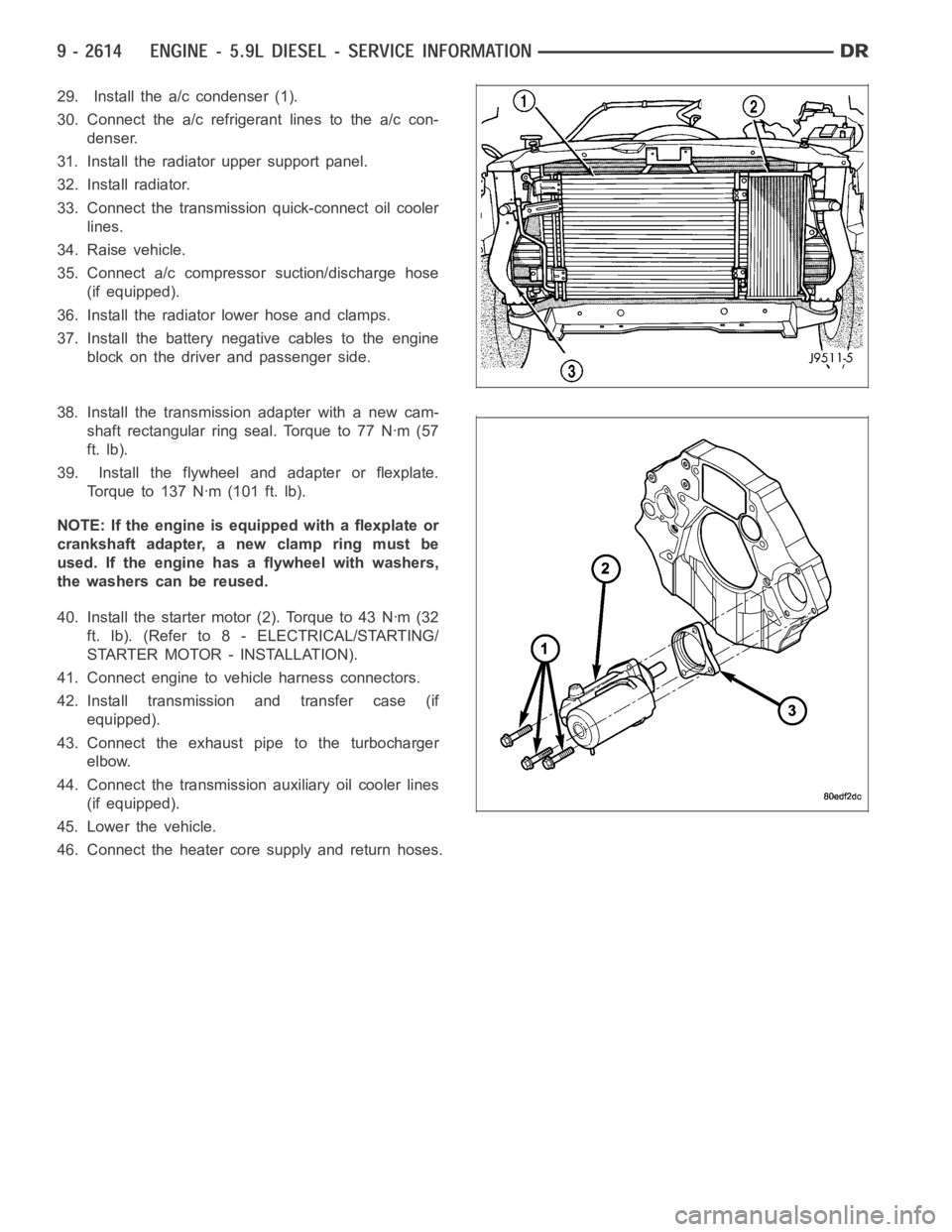
29. Install the a/c condenser (1).
30. Connect the a/c refrigerant lines to the a/c con-
denser.
31. Install the radiator upper support panel.
32. Install radiator.
33. Connect the transmission quick-connect oil cooler
lines.
34. Raise vehicle.
35. Connect a/c compressor suction/discharge hose
(if equipped).
36. Install the radiator lower hose and clamps.
37. Install the battery negative cables to the engine
block on the driver and passenger side.
38. Install the transmission adapter with a new cam-
shaft rectangular ring seal. Torque to 77 Nꞏm (57
ft. lb).
39. Install the flywheel and adapter or flexplate.
Torque to 137 Nꞏm (101 ft. lb).
NOTE: If the engine is equipped with a flexplate or
crankshaft adapter, a new clamp ring must be
used. If the engine has a flywheel with washers,
the washers can be reused.
40. Install the starter motor (2). Torque to 43 Nꞏm (32
ft. lb). (Refer to 8 - ELECTRICAL/STARTING/
STARTER MOTOR - INSTALLATION).
41. Connect engine to vehicle harness connectors.
42. Install transmission and transfer case (if
equipped).
43. Connect the exhaust pipe to the turbocharger
elbow.
44. Connect the transmission auxiliary oil cooler lines
(if equipped).
45. Lower the vehicle.
46. Connect the heater core supply and return hoses.
Page 1935 of 5267
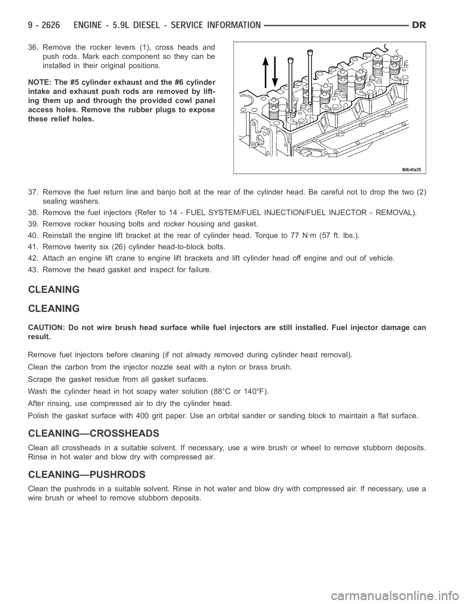
36. Remove the rocker levers (1), cross heads and
push rods. Mark each component so they can be
installed in their original positions.
NOTE: The #5 cylinder exhaust and the #6 cylinder
intake and exhaust push rods are removed by lift-
ing them up and through the provided cowl panel
access holes. Remove the rubber plugs to expose
these relief holes.
37. Remove the fuel return line and banjo bolt at the rear of the cylinder head. Be careful not to drop the two (2)
sealing washers.
38. Remove the fuel injectors (Refer to 14 - FUEL SYSTEM/FUEL INJECTION/FUEL INJECTOR - REMOVAL).
39. Remove rocker housing bolts and rocker housing and gasket.
40. Reinstall the engine lift bracket at the rear of cylinder head. Torque to77Nꞏm(57ft.lbs.).
41. Remove twenty six (26) cylinder head-to-block bolts.
42. Attach an engine lift crane to engine lift brackets and lift cylinder head off engine and out of vehicle.
43. Remove the head gasket and inspect for failure.
CLEANING
CLEANING
CAUTION: Do not wire brush head surface while fuel injectors are still installed. Fuel injector damage can
result.
Remove fuel injectors before cleaning (if not already removed during cylinder head removal).
Clean the carbon from the injector nozzle seat with a nylon or brass brush.
Scrape the gasket residuefrom all gasket surfaces.
Wash the cylinder head in hot soapy water solution (88°C or 140°F).
After rinsing, use compressed air to dry the cylinder head.
Polish the gasket surface with 400 grit paper. Use an orbital sander or sanding block to maintain a flat surface.
CLEANING—CROSSHEADS
Clean all crossheads in a suitable solvent. If necessary, use a wire brush or wheel to remove stubborn deposits.
Rinse in hot water and blow dry with compressed air.
CLEANING—PUSHRODS
Clean the pushrods in a suitable solvent. Rinse in hot water and blow dry with compressed air. If necessary, use a
wire brush or wheel to remove stubborn deposits.
Page 1979 of 5267
SEAL - CRANKSHAFT OIL - REAR
REMOVAL
1. Disconnect the battery negative cables.
2. Remove the transmission and transfer case (if
equipped).
3. Remove the clutch cover and disc (if manual trans-
mission equipped) (Refer to 6 - CLUTCH/CLUTCH
DISC - REMOVAL).
4. Remove the flywheel or converter drive plate.
5. Remove the flywheel adapter plate.
6. Drill holes 180° apart into the seal. Be careful not
to contact the drill against the crankshaft.
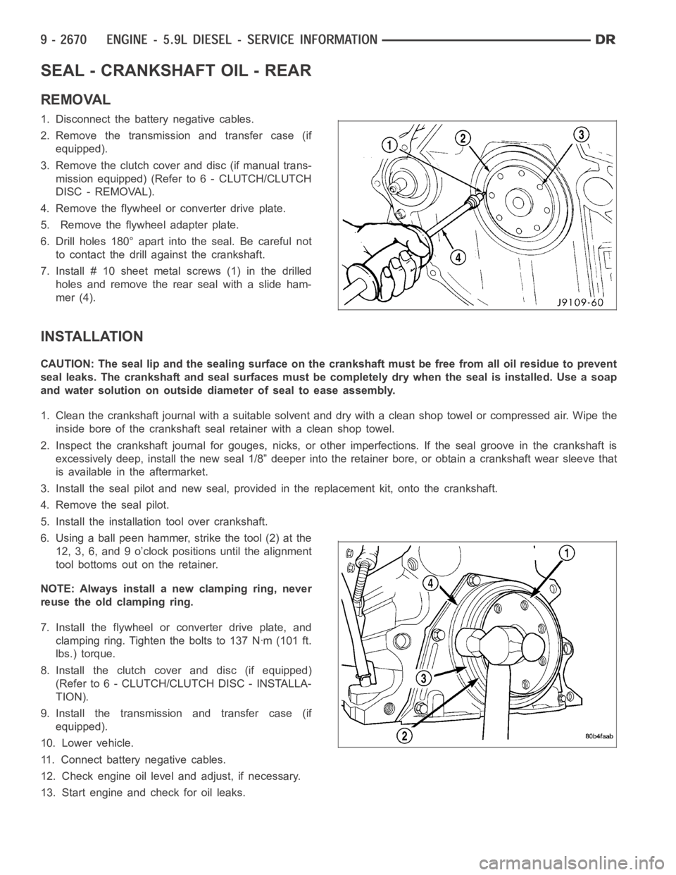
7. Install # 10 sheet metalscrews (1) in the drilled
holes and remove the rear seal with a slide ham-
mer (4).
INSTALLATION
CAUTION: The seal lip and the sealing surface on the crankshaft must be freefrom all oil residue to prevent
seal leaks. The crankshaft and seal surfaces must be completely dry when the seal is installed. Use a soap
and water solution on outside diameter of seal to ease assembly.
1. Clean the crankshaft journal with a suitable solvent and dry with a cleanshop towel or compressed air. Wipe the
inside bore of the crankshaft seal retainer with a clean shop towel.
2. Inspect the crankshaft journal forgouges, nicks, or other imperfections. If the seal groove in the crankshaft is
excessively deep, install the new seal 1/8” deeper into the retainer bore,or obtain a crankshaft wear sleeve that
is available in the aftermarket.
3. Install the seal pilot and new seal, provided in the replacement kit, onto the crankshaft.
4. Remove the seal pilot.
5. Install the installation tool over crankshaft.
6. Using a ball peen hammer, strike the tool (2) at the
12, 3, 6, and 9 o’clock positions until the alignment
tool bottoms out on the retainer.
NOTE: Always install a new clamping ring, never
reuse the old clamping ring.
7. Install the flywheel or converter drive plate, and
clamping ring. Tighten the bolts to 137 Nꞏm (101 ft.
lbs.) torque.
8. Install the clutch cover and disc (if equipped)
(Refer to 6 - CLUTCH/CLUTCH DISC - INSTALLA-
TION).
9. Install the transmission and transfer case (if
equipped).
10. Lower vehicle.
11. Connect battery negative cables.
12. Check engine oil level and adjust, if necessary.
13. Start engine and check for oil leaks.
Page 1980 of 5267
RETAINER - CRANK REAR OIL SEAL
REMOVAL
1. Disconnect the battery negative cables.
2. Raise vehicle on hoist.
3. Remove the oil pan drain plug and drain the engine
oil. Re-install plug and torque to 50 Nꞏm (44 ft. lbs.)
torque.
4. Remove transmission and transfer case (if
equipped) from vehicle.
5. Remove flywheel or torque converter drive plate.
6. Remove flywheel adapter plate.
7. Disconnect starter cables from starter motor.
8. Remove starter motor (Refer to 8 - ELECTRICAL/
STARTING/STARTER MOTOR - REMOVAL) and
transmission adapter plate assembly.
9. Remove four 4 oil pan rear bolts. Slide a feeler
gauge between the seal retainer and oil pan gasket
to break the seal.
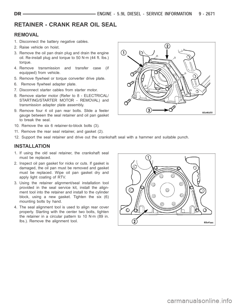
10. Remove the six 6 retainer-to-block bolts (3).
11. Remove the rear seal retainer, and gasket (2).
12. Support the seal retainer and drive out the crankshaft seal with a hammer and suitable punch.
INSTALLATION
1. If using the old seal retainer, the crankshaft seal
must be replaced.
2. Inspect oil pan gasket for nicks or cuts. If gasket is
damaged, the oil pan must be removed and gasket
must be replaced. Wipe oil pan gasket dry and
apply light coating of RTV.
3. Using the retainer alignment/seal installation tool
provided in the seal service kit, install the align-
ment tool into the retainer and install to the cylinder
block, using a new gasket. Tighten the six (6)
mounting bolts by hand.
4. The seal alignment tool is used to align rear cover
properly. Starting with the center two bolts, tighten
the retainer in a circular pattern to 10 Nꞏm (89 in.
lbs.). Remove the alignment tool.
Page 1981 of 5267
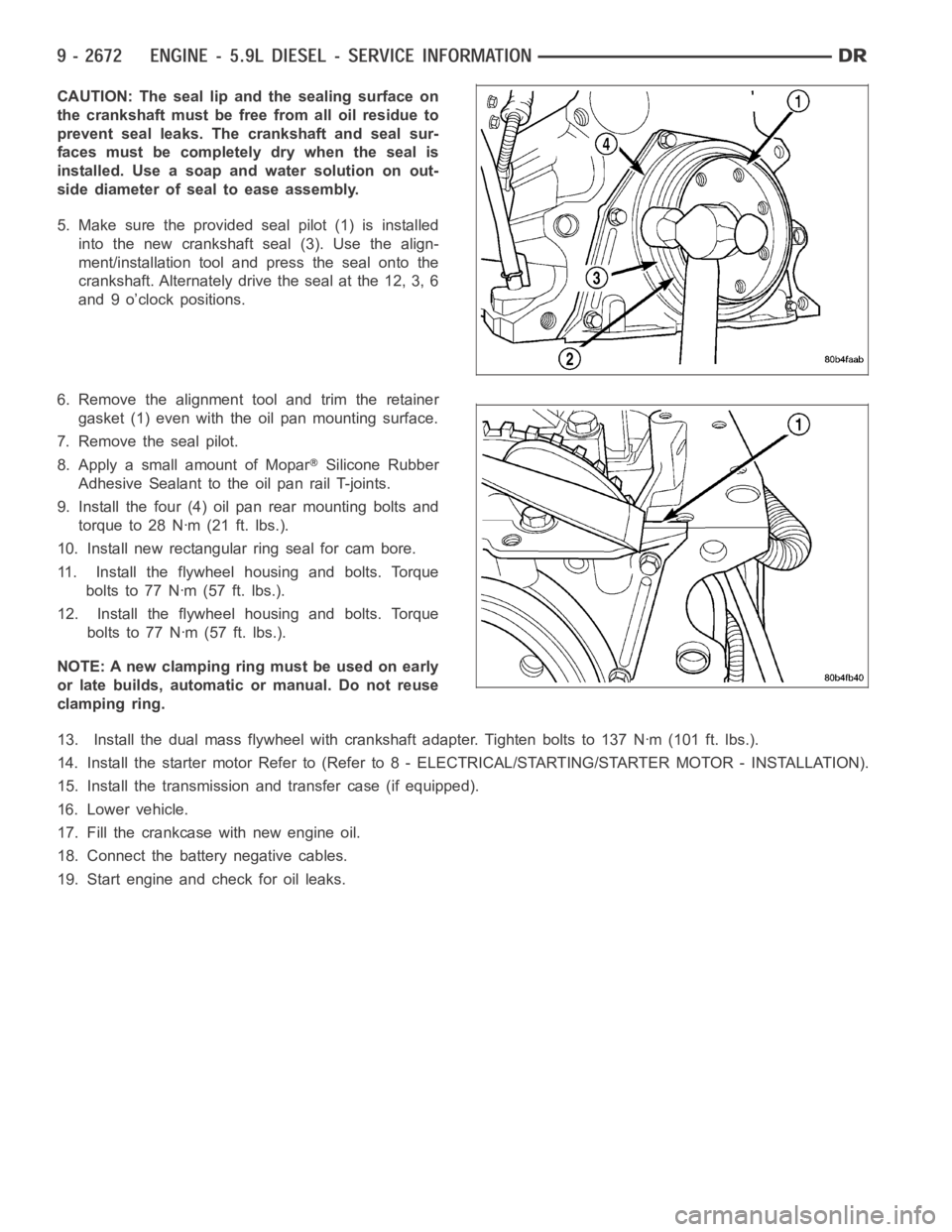
CAUTION: The seal lip and the sealing surface on
the crankshaft must be free from all oil residue to
prevent seal leaks. The crankshaft and seal sur-
faces must be completely dry when the seal is
installed. Use a soap and water solution on out-
side diameter of seal to ease assembly.
5. Make sure the provided seal pilot (1) is installed
into the new crankshaft seal (3). Use the align-
ment/installation tool and press the seal onto the
crankshaft. Alternately drive the seal at the 12, 3, 6
and 9 o’clock positions.
6. Remove the alignment tool and trim the retainer
gasket (1) even with the oil pan mounting surface.
7. Remove the seal pilot.
8. Apply a small amount of Mopar
Silicone Rubber
Adhesive Sealant to the oil pan rail T-joints.
9. Install the four (4) oil pan rear mounting bolts and
torque to 28 Nꞏm (21 ft. lbs.).
10. Install new rectangular ring seal for cam bore.
11. Install the flywheel housing and bolts. Torque
boltsto77Nꞏm(57ft.lbs.).
12. Install the flywheel housing and bolts. Torque
boltsto77Nꞏm(57ft.lbs.).
NOTE: A new clamping ring must be used on early
or late builds, automatic or manual. Do not reuse
clamping ring.
13. Install the dual mass flywheel with crankshaft adapter. Tighten boltsto 137 Nꞏm (101 ft. lbs.).
14. Install the starter motor Refer to (Refer to 8 - ELECTRICAL/STARTING/STA R T E R M O TO R - I N S TA L L AT I O N ) .
15. Install the transmission and transfer case (if equipped).
16. Lower vehicle.
17. Fill the crankcase with new engine oil.
18. Connect the battery negative cables.
19. Start engine and check for oil leaks.
Page 2005 of 5267
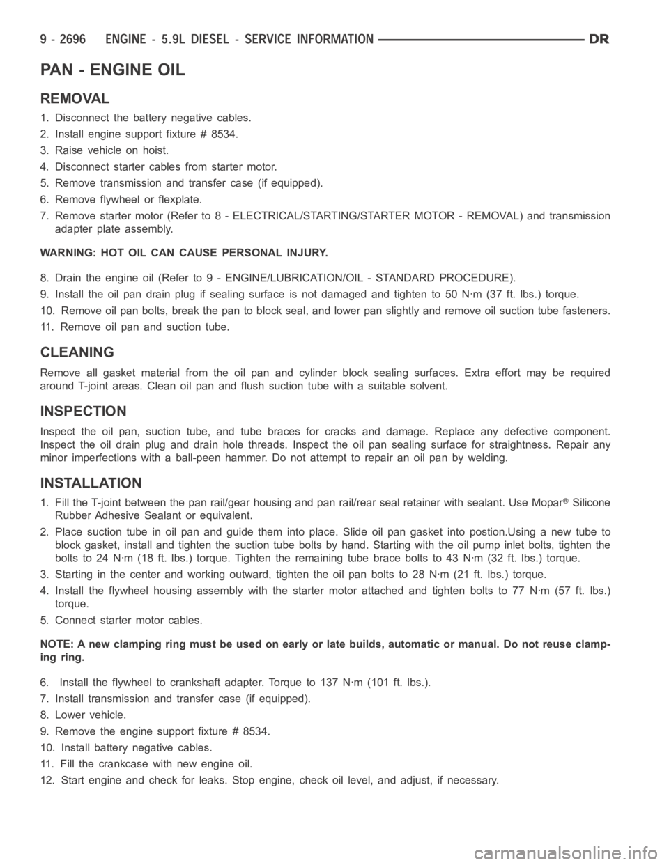
PA N - E N G I N E O I L
REMOVAL
1. Disconnect the battery negative cables.
2. Install engine support fixture # 8534.
3. Raise vehicle on hoist.
4. Disconnect starter cables from starter motor.
5. Remove transmission and transfer case (if equipped).
6. Remove flywheel or flexplate.
7. Remove starter motor (Refer to 8 - ELECTRICAL/STARTING/STARTER MOTOR -REMOVAL) and transmission
adapter plate assembly.
WARNING: HOT OIL CAN CAUSE PERSONAL INJURY.
8. Drain the engine oil (Refer to 9 - ENGINE/LUBRICATION/OIL - STANDARD PROCEDURE).
9. Install the oil pan drain plug if sealing surface is not damaged and tighten to 50 Nꞏm (37 ft. lbs.) torque.
10. Remove oil pan bolts, break the pan to block seal, and lower pan slightlyandremoveoilsuctiontubefasteners.
11. Remove oil pan and suction tube.
CLEANING
Remove all gasket material from the oil pan and cylinder block sealing surfaces. Extra effort may be required
around T-joint areas. Clean oil pan and flush suction tube with a suitable solvent.
INSPECTION
Inspect the oil pan, suction tube, and tube braces for cracks and damage. Replace any defective component.
Inspect the oil drain plug and drain hole threads. Inspect the oil pan sealing surface for straightness. Repair any
minor imperfections with a ball-peen hammer. Do not attempt to repair an oil pan by welding.
INSTALLATION
1. Fill the T-joint between the pan rail/gear housing and pan rail/rear seal retainer with sealant. Use MoparSilicone
Rubber Adhesive Sealant or equivalent.
2. Place suction tube in oil pan and guide them into place. Slide oil pan gasket into postion.Using a new tube to
block gasket, install and tighten the suction tube bolts by hand. Startingwith the oil pump inlet bolts, tighten the
bolts to 24 Nꞏm (18 ft. lbs.) torque. Tighten the remaining tube brace boltsto 43 Nꞏm (32 ft. lbs.) torque.
3. Starting in the center and working outward, tighten the oil pan bolts to 28Nꞏm(21ft.lbs.)torque.
4. Install the flywheel housing assembly with the starter motor attached and tighten bolts to 77 Nꞏm (57 ft. lbs.)
torque.
5. Connect starter motor cables.
NOTE: A new clamping ring must be used on early or late builds, automatic or manual. Do not reuse clamp-
ing ring.
6. Install the flywheel to crankshaft adapter. Torque to 137 Nꞏm (101 ft. lbs.).
7. Install transmission and transfer case (if equipped).
8. Lower vehicle.
9. Remove the engine support fixture # 8534.
10. Install battery negative cables.
11. Fill the crankcase with new engine oil.
12. Start engine and check for leaks. Stop engine, check oil level, and adjust, if necessary.
Page 2026 of 5267
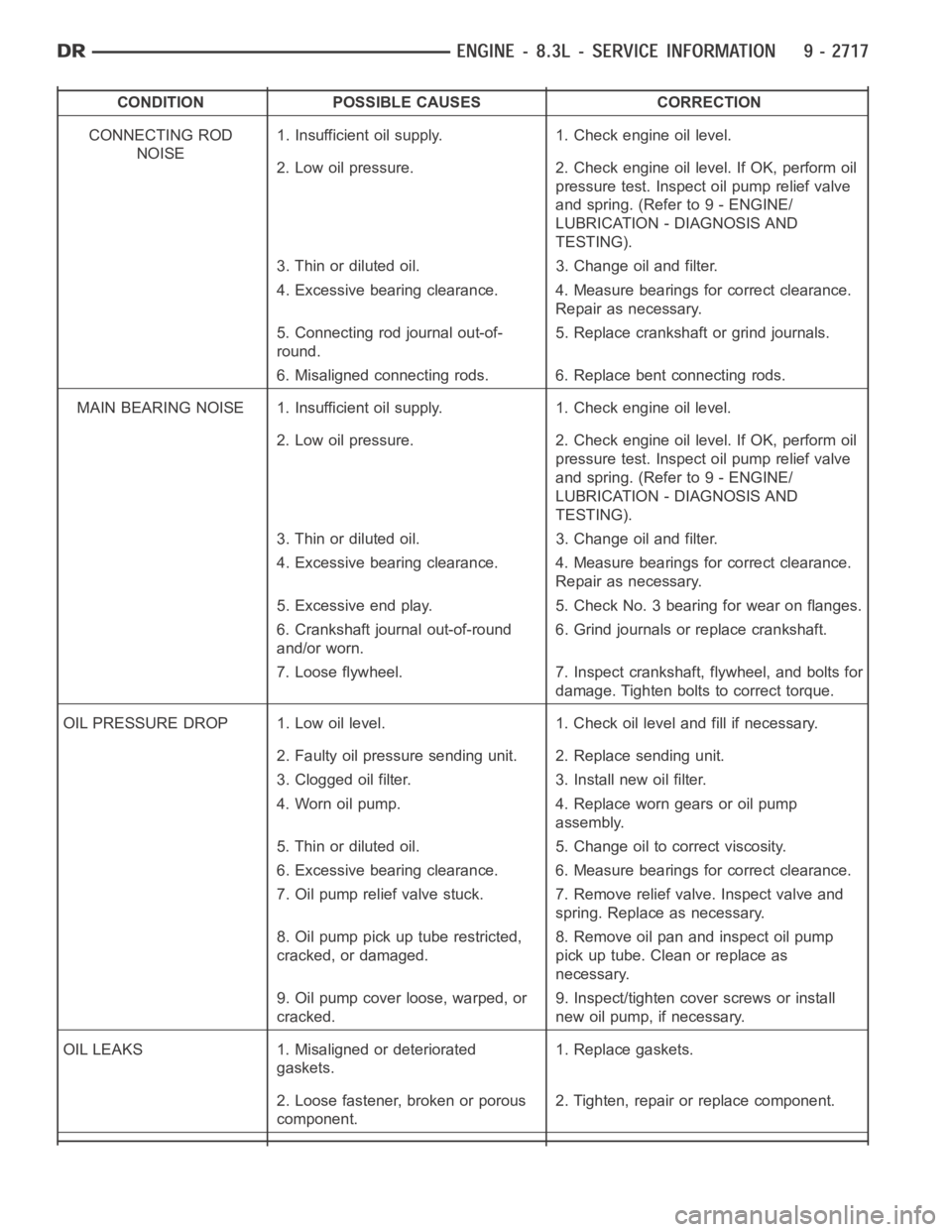
CONDITION POSSIBLE CAUSES CORRECTION
CONNECTING ROD
NOISE1. Insufficient oil supply. 1. Check engine oil level.
2. Low oil pressure. 2. Check engine oil level. If OK, perform oil
pressure test. Inspect oil pump relief valve
and spring. (Refer to 9 - ENGINE/
LUBRICATION - DIAGNOSIS AND
TESTING).
3. Thin or diluted oil. 3. Change oil and filter.
4. Excessive bearing clearance. 4. Measure bearings for correct clearance.
Repair as necessary.
5. Connecting rod journal out-of-
round.5. Replace crankshaft or grind journals.
6. Misaligned connecting rods. 6. Replace bent connecting rods.
MAIN BEARING NOISE 1. Insufficient oil supply. 1. Check engine oil level.
2. Low oil pressure. 2. Check engine oil level. If OK, perform oil
pressure test. Inspect oil pump relief valve
and spring. (Refer to 9 - ENGINE/
LUBRICATION - DIAGNOSIS AND
TESTING).
3. Thin or diluted oil. 3. Change oil and filter.
4. Excessive bearing clearance. 4. Measure bearings for correct clearance.
Repair as necessary.
5. Excessive end play. 5. Check No. 3 bearing for wear on flanges.
6. Crankshaft journal out-of-round
and/or worn.6. Grind journals or replace crankshaft.
7. Loose flywheel. 7. Inspect crankshaft, flywheel, and bolts for
damage. Tighten bolts to correct torque.
OIL PRESSURE DROP 1. Low oil level. 1. Check oil level and fill if necessary.
2. Faulty oil pressure sending unit. 2. Replace sending unit.
3. Clogged oil filter. 3. Install new oil filter.
4. Worn oil pump. 4. Replace worn gears or oil pump
assembly.
5. Thin or diluted oil. 5. Change oil to correct viscosity.
6. Excessive bearing clearance. 6. Measure bearings for correct clearance.
7. Oil pump relief valve stuck. 7. Remove relief valve. Inspect valve and
spring. Replace as necessary.
8. Oil pump pick up tube restricted,
cracked, or damaged.8. Remove oil pan and inspect oil pump
pick up tube. Clean or replace as
necessary.
9. Oil pump cover loose, warped, or
cracked.9. Inspect/tighten cover screws or install
new oil pump, if necessary.
OIL LEAKS 1. Misaligned or deteriorated
gaskets.1. Replace gaskets.
2. Loose fastener, broken or porous
component.2. Tighten, repair or replace component.
Page 2045 of 5267
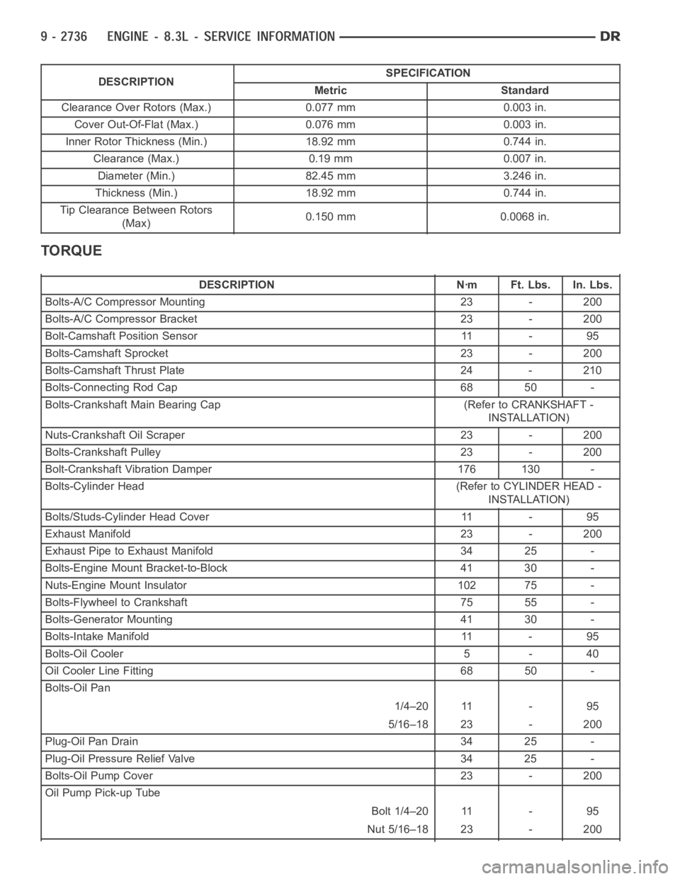
DESCRIPTIONSPECIFICATION
Metric Standard
Clearance Over Rotors (Max.) 0.077 mm 0.003 in.
Cover Out-Of-Flat (Max.) 0.076 mm 0.003 in.
Inner Rotor Thickness (Min.) 18.92 mm 0.744 in.
Clearance (Max.) 0.19 mm 0.007 in.
Diameter (Min.) 82.45 mm 3.246 in.
Thickness (Min.) 18.92 mm 0.744 in.
Tip Clearance Between Rotors
(Max)0.150 mm 0.0068 in.
TORQUE
DESCRIPTION Nꞏm Ft. Lbs. In. Lbs.
Bolts-A/C Compressor Mounting 23 - 200
Bolts-A/C Compressor Bracket 23 - 200
Bolt-Camshaft Position Sensor 11 - 95
Bolts-Camshaft Sprocket 23 - 200
Bolts-Camshaft Thrust Plate 24 - 210
Bolts-Connecting Rod Cap 68 50 -
Bolts-Crankshaft Main Bearing Cap (Refer to CRANKSHAFT -
INSTALLATION)
Nuts-Crankshaft Oil Scraper 23 - 200
Bolts-Crankshaft Pulley 23 - 200
Bolt-Crankshaft Vibration Damper 176 130 -
Bolts-Cylinder Head (Refer to CYLINDER HEAD -
INSTALLATION)
Bolts/Studs-Cylinder Head Cover 11 - 95
Exhaust Manifold 23 - 200
Exhaust Pipe to Exhaust Manifold 34 25 -
Bolts-Engine Mount Bracket-to-Block 41 30 -
Nuts-Engine Mount Insulator 102 75 -
Bolts-Flywheel to Crankshaft 75 55 -
Bolts-Generator Mounting 41 30 -
Bolts-Intake Manifold 11 - 95
Bolts-Oil Cooler 5 - 40
Oil Cooler Line Fitting 68 50 -
Bolts-Oil Pan
1/4–20 11 - 95
5/16–18 23 - 200
Plug-Oil Pan Drain 34 25 -
Plug-Oil Pressure Relief Valve 34 25 -
Bolts-Oil Pump Cover 23 - 200
Oil Pump Pick-up Tube
Bolt 1/4–20 11 - 95
Nut 5/16–18 23 - 200
Page 2081 of 5267
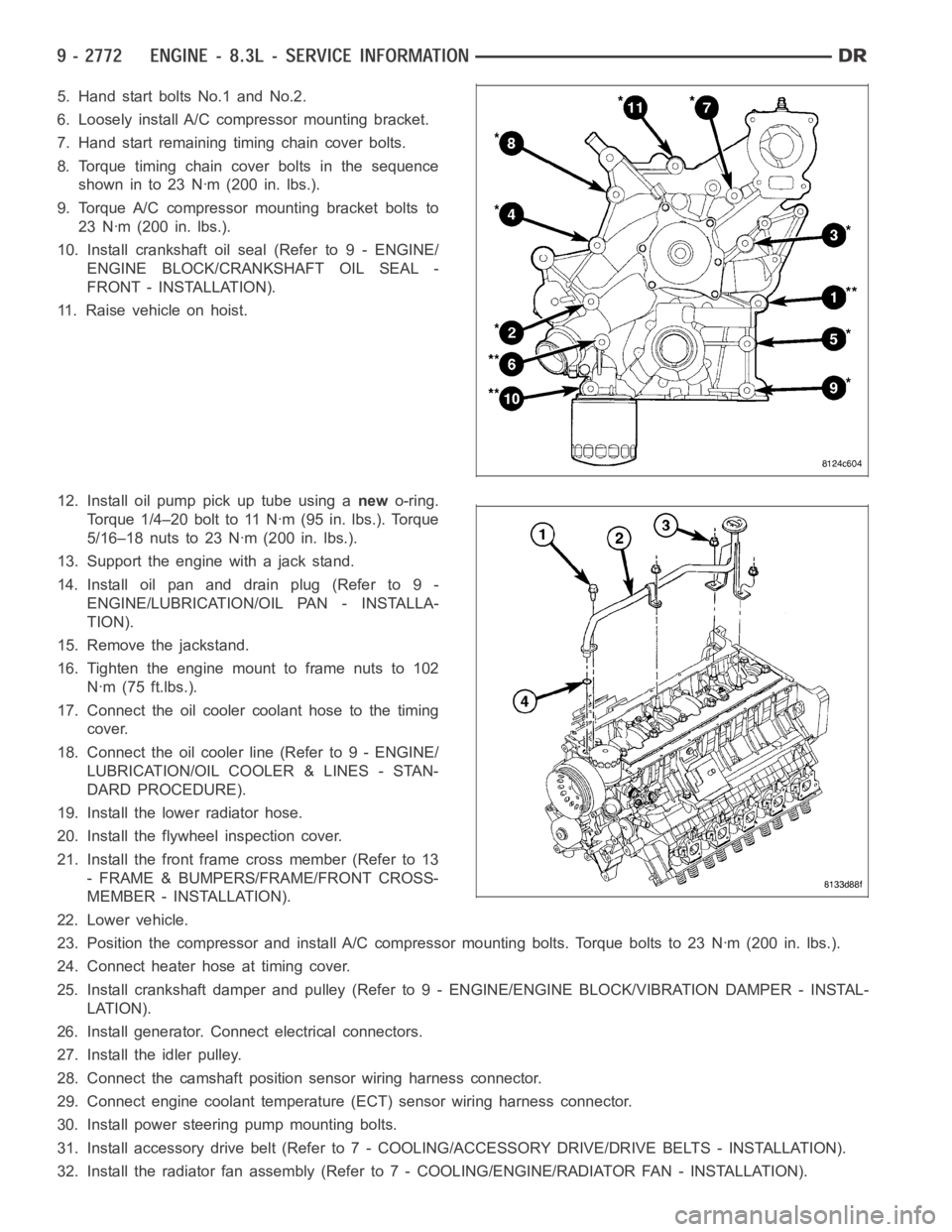
5. Hand start bolts No.1 and No.2.
6. Loosely install A/C compressor mounting bracket.
7. Hand start remaining timing chain cover bolts.
8. Torque timing chain cover bolts in the sequence
showninto23Nꞏm(200in.lbs.).
9. Torque A/C compressor mounting bracket bolts to
23 Nꞏm (200 in. lbs.).
10. Install crankshaft oil seal (Refer to 9 - ENGINE/
ENGINE BLOCK/CRANKSHAFT OIL SEAL -
FRONT - INSTALLATION).
11. Raise vehicle on hoist.
12. Install oil pump pick up tube using anewo-ring.
Torque 1/4–20 bolt to 11 Nꞏm (95 in. lbs.). Torque
5/16–18 nuts to 23 Nꞏm (200 in. lbs.).
13. Support the engine with a jack stand.
14. Install oil pan and drain plug (Refer to 9 -
ENGINE/LUBRICATION/OIL PAN - INSTALLA-
TION).
15. Remove the jackstand.
16. Tighten the engine mount to frame nuts to 102
Nꞏm (75 ft.lbs.).
17. Connect the oil cooler coolant hose to the timing
cover.
18. Connect the oil cooler line (Refer to 9 - ENGINE/
LUBRICATION/OIL COOLER & LINES - STAN-
DARD PROCEDURE).
19. Install the lower radiator hose.
20. Install the flywheel inspection cover.
21. Install the front frame cross member (Refer to 13
- FRAME & BUMPERS/FRAME/FRONT CROSS-
MEMBER - INSTALLATION).
22. Lower vehicle.
23. Position the compressor and install A/C compressor mounting bolts. Torque bolts to 23 Nꞏm (200 in. lbs.).
24. Connect heater hose at timing cover.
25. Install crankshaft damper and pulley (Refer to 9 - ENGINE/ENGINE BLOCK/VIBRATION DAMPER - INSTAL-
LATION).
26. Install generator. Connect electrical connectors.
27. Install the idler pulley.
28. Connect the camshaft position sensor wiring harness connector.
29. Connect engine coolant temperature (ECT) sensor wiring harness connector.
30. Install power steering pump mounting bolts.
31. Install accessory drive belt (Refer to 7 - COOLING/ACCESSORY DRIVE/DRIVE BELTS - INSTALLATION).
32. Install the radiator fan assembly (Refer to 7 - COOLING/ENGINE/RADIATOR FAN - INSTALLATION).
Page 2095 of 5267
2. Apply an 1/8 in. bead of Mopar Engine RTV at the two joints between the cylinder block to timing chain case
cover and the two joints between the rear main seal retainer and engine block.
3. Position oil pan and gasket to engine block, seat the oil level indicatortube in the oil pan and hand start all
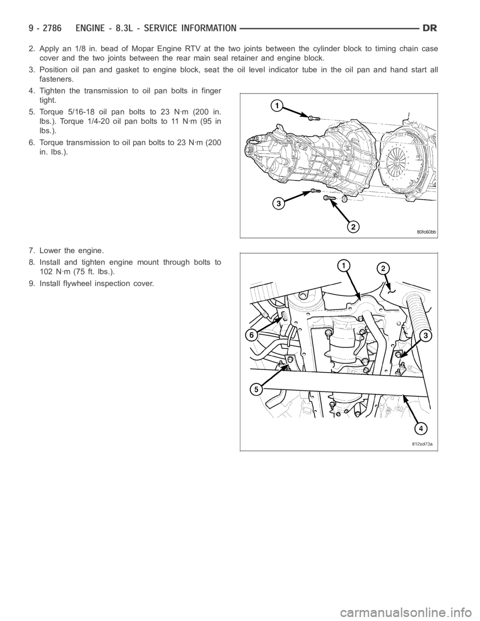
fasteners.
4. Tighten the transmission to oil pan bolts in finger
tight.
5. Torque 5/16-18 oil pan bolts to 23 Nꞏm (200 in.
lbs.). Torque 1/4-20 oil pan bolts to 11 Nꞏm (95 in
lbs.).
6. Torque transmission to oil pan bolts to 23 Nꞏm (200
in. lbs.).
7. Lower the engine.
8. Install and tighten engine mount through bolts to
102 Nꞏm (75 ft. lbs.).
9. Install flywheel inspection cover.