DODGE RAM SRT-10 2006 Service Repair Manual
Manufacturer: DODGE, Model Year: 2006, Model line: RAM SRT-10, Model: DODGE RAM SRT-10 2006Pages: 5267, PDF Size: 68.7 MB
Page 2381 of 5267
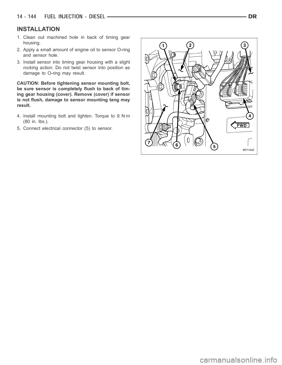
INSTALLATION
1. Clean out machined hole in back of timing gear
housing.
2. Apply a small amount of engine oil to sensor O-ring
and sensor hole.
3. Install sensor into timing gear housing with a slight
rocking action. Do not twist sensor into position as
damagetoO-ringmayresult.
CAUTION: Before tightening sensor mounting bolt,
be sure sensor is completely flush to back of tim-
ing gear housing (cover). Remove (cover) if sensor
is not flush, damage to sensor mounting tang may
result.
4. Install mounting bolt and tighten. Torque to 9 Nꞏm
(80 in. lbs.).
5. Connect electrical connector (5) to sensor.
Page 2382 of 5267
SENSOR-CRANKSHAFT POSITION
DESCRIPTION
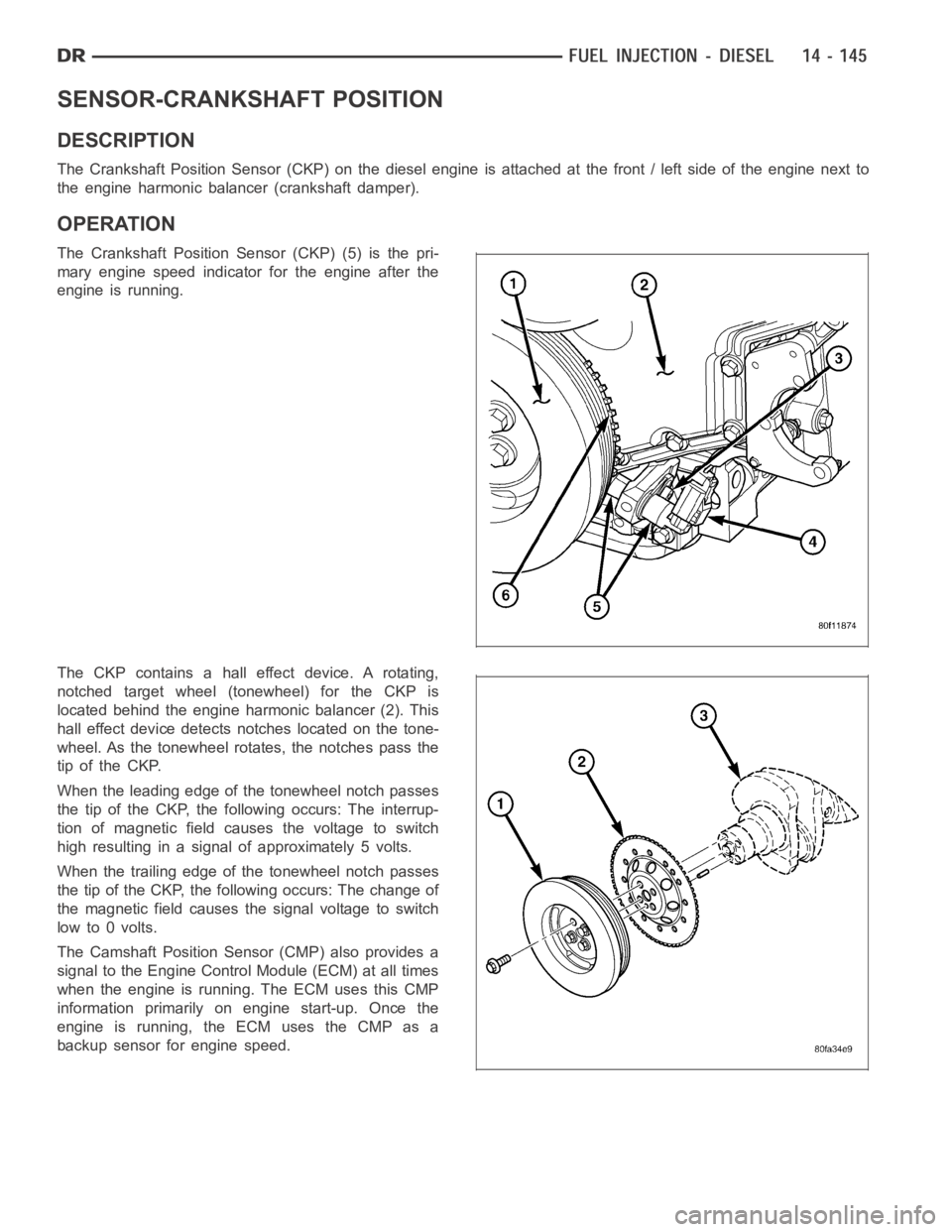
The Crankshaft Position Sensor (CKP) on the diesel engine is attached at thefront/leftsideoftheenginenextto
the engine harmonic balancer (crankshaft damper).
OPERATION
The Crankshaft Position Sensor (CKP) (5) is the pri-
mary engine speed indicator for the engine after the
engine is running.
The CKP contains a hall effect device. A rotating,
notched target wheel (tonewheel) for the CKP is
located behind the engine harmonic balancer (2). This
hall effect device detects notches located on the tone-
wheel. As the tonewheel rotates, the notches pass the
tip of the CKP.
When the leading edge of the tonewheel notch passes
the tip of the CKP, the following occurs: The interrup-
tion of magnetic field causes the voltage to switch
high resulting in a signal of approximately 5 volts.
When the trailing edge of the tonewheel notch passes
the tip of the CKP, the following occurs: The change of
the magnetic field causes the signal voltage to switch
lowto0volts.
The Camshaft Position Sensor (CMP) also provides a
signal to the Engine Control Module (ECM) at all times
when the engine is running. The ECM uses this CMP
information primarily on engine start-up. Once the
engine is running, the ECM uses the CMP as a
backup sensor for engine speed.
Page 2383 of 5267
REMOVAL
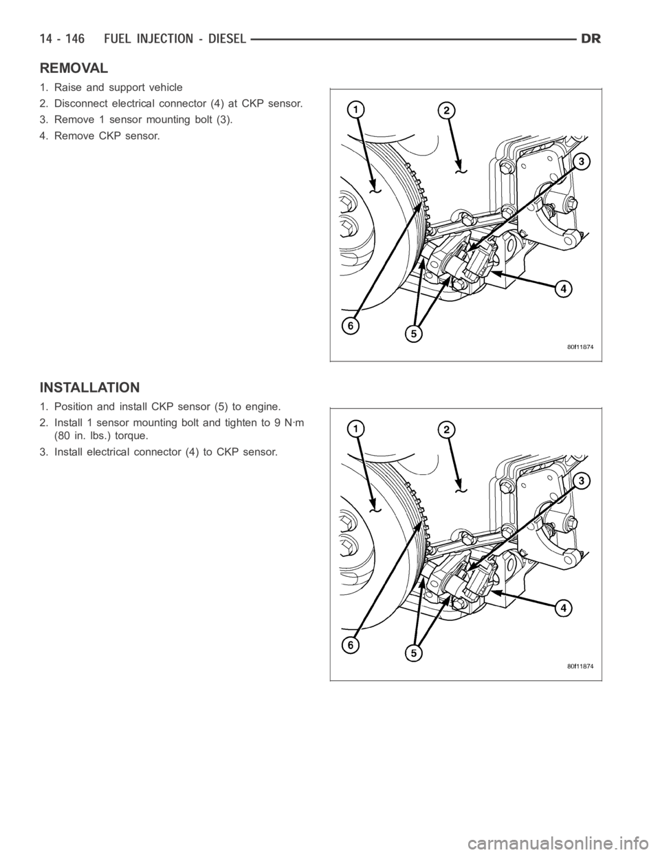
1. Raise and support vehicle
2. Disconnect electrical connector (4) at CKP sensor.
3. Remove 1 sensor mounting bolt (3).
4. Remove CKP sensor.
INSTALLATION
1. Position and install CKP sensor (5) to engine.
2. Install 1 sensor mounting bolt and tighten to 9 Nꞏm
(80 in. lbs.) torque.
3. Install electrical connector (4) to CKP sensor.
Page 2384 of 5267
ACTUATOR - FUEL CONTROL
DESCRIPTION
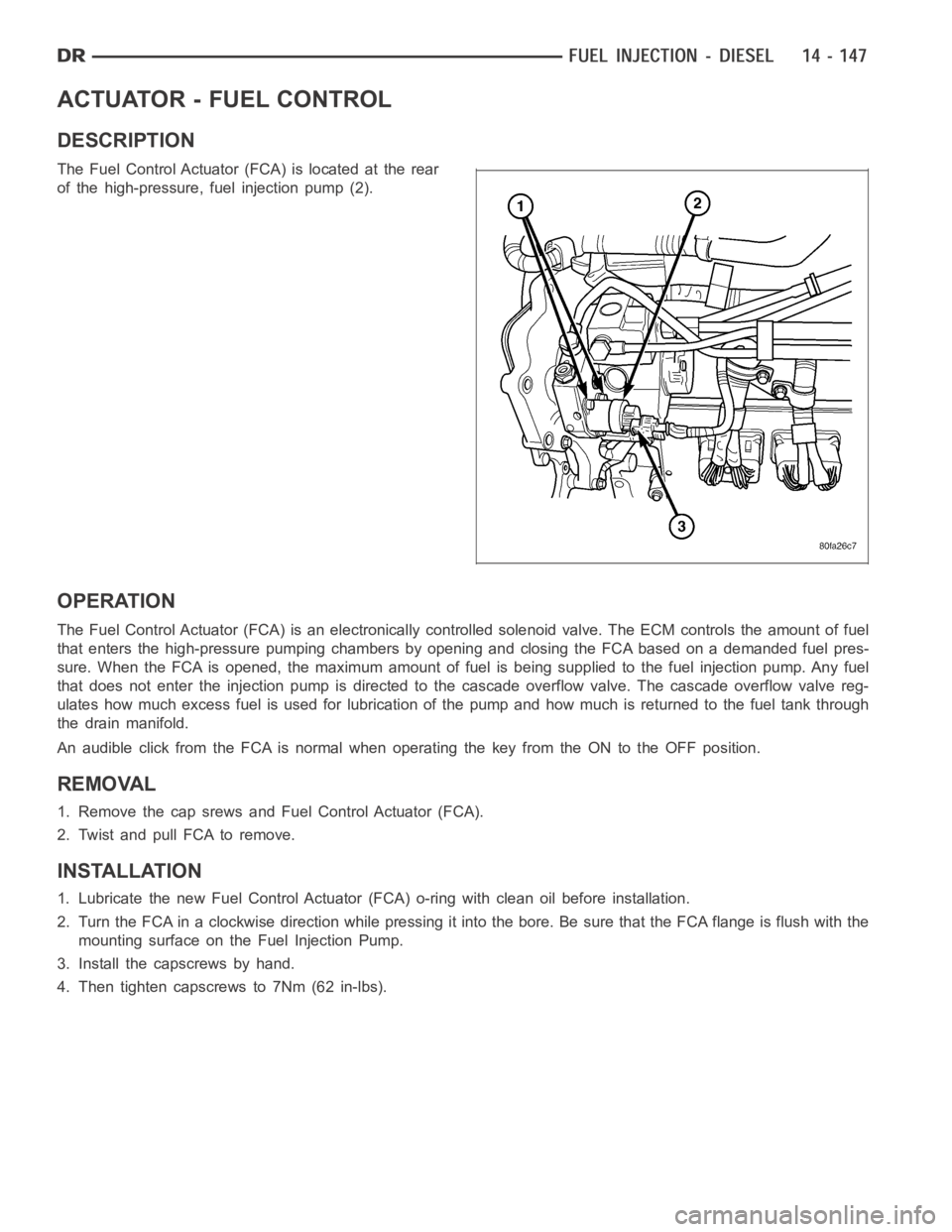
The Fuel Control Actuator (FCA) is located at the rear
of the high-pressure, fuel injection pump (2).
OPERATION
The Fuel Control Actuator (FCA) is an electronically controlled solenoidvalve. The ECM controls the amount of fuel
that enters the high-pressure pumping chambers by opening and closing theFCA based on a demanded fuel pres-
sure. When the FCA is opened, the maximum amount of fuel is being supplied tothe fuel injection pump. Any fuel
that does not enter the injection pump is directed to the cascade overflow valve. The cascade overflow valve reg-
ulates how much excess fuel is used for lubrication of the pump and how much is returned to the fuel tank through
the drain manifold.
An audible click from the FCA is normal when operating the key from the ON to the OFF position.
REMOVAL
1. Remove the cap srews and Fuel Control Actuator (FCA).
2. Twist and pull FCA to remove.
INSTALLATION
1. Lubricate the new Fuel Control Actuator (FCA) o-ring with clean oil before installation.
2. Turn the FCA in a clockwise direction while pressing it into the bore. Be sure that the FCA flange is flush with the
mounting surface on the Fuel Injection Pump.
3. Install the capscrews by hand.
4. Then tighten capscrews to 7Nm (62 in-lbs).
Page 2385 of 5267
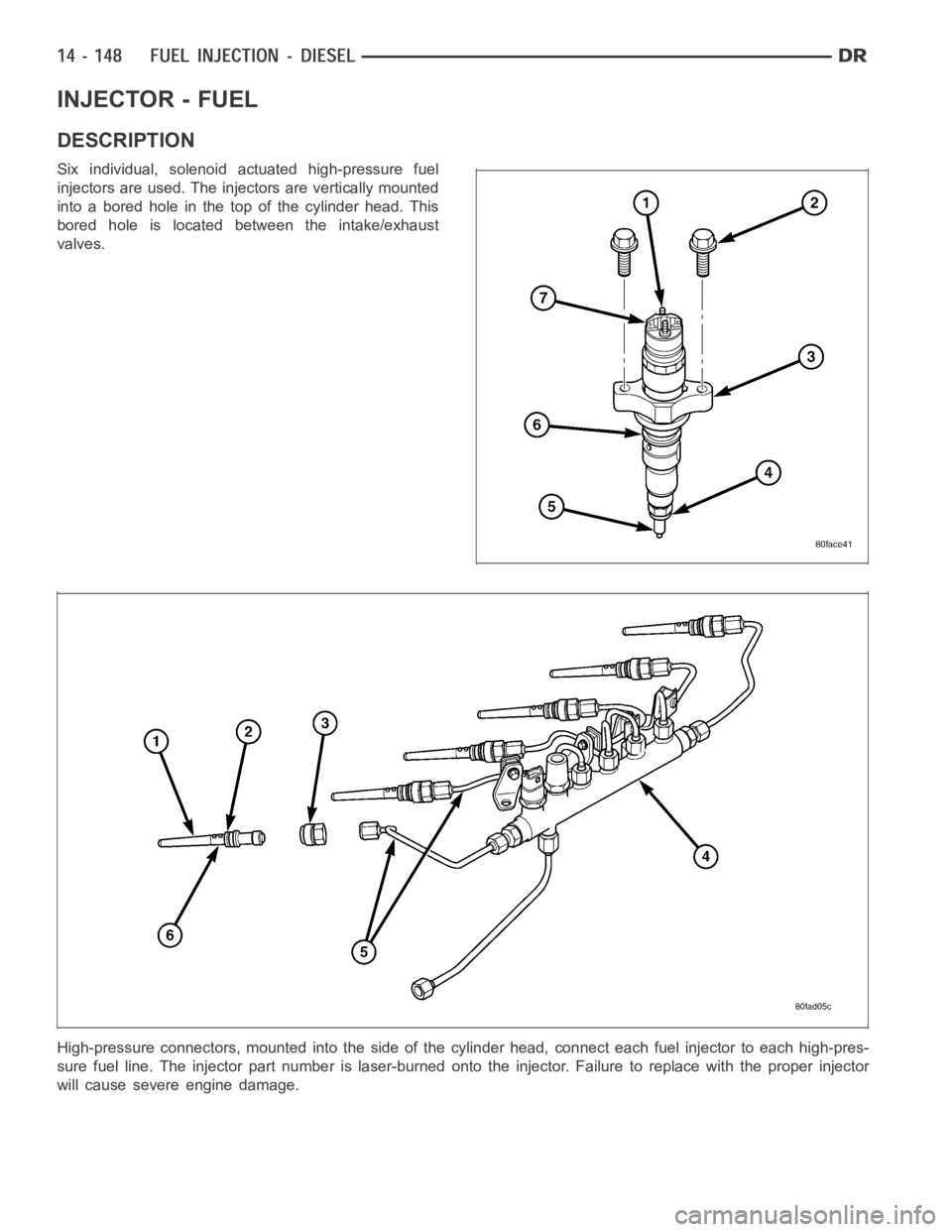
INJECTOR - FUEL
DESCRIPTION
Six individual, solenoid actuated high-pressure fuel
injectors are used. The injectors are vertically mounted
into a bored hole in the top of the cylinder head. This
bored hole is located between the intake/exhaust
valves.
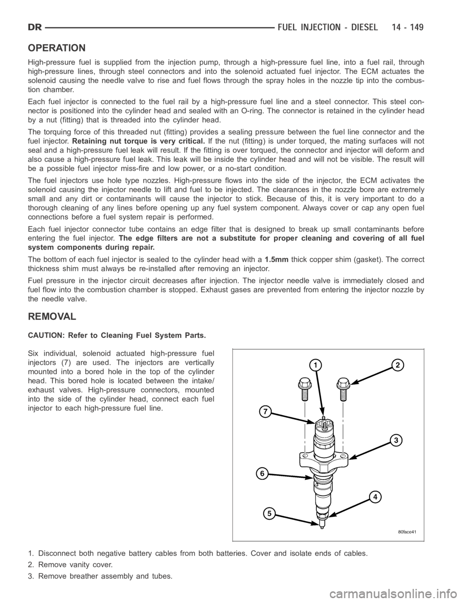
High-pressure connectors, mounted into the side of the cylinder head, connect each fuel injector to each high-pres-
sure fuel line. The injector part number is laser-burned onto the injector. Failure to replace with the proper injector
will cause severe engine damage.
Page 2386 of 5267
OPERATION
High-pressure fuel is supplied from the injection pump, through a high-pressure fuel line, into a fuel rail, through
high-pressure lines, through steel connectors and into the solenoid actuated fuel injector. The ECM actuates the
solenoid causing the needle valve to rise and fuel flows through the spray holes in the nozzle tip into the combus-
tion chamber.
Each fuel injector is connected to the fuel rail by a high-pressure fuel line and a steel connector. This steel con-
nector is positioned into the cylinder head and sealed with an O-ring. The connector is retained in the cylinder head
by a nut (fitting) that is threaded into the cylinder head.
The torquing force of this threaded nut (fitting) provides a sealing pressure between the fuel line connector and the
fuel injector.Retaining nut torque is very critical.If the nut (fitting) is under torqued, the mating surfaces will not
seal and a high-pressure fuel leak will result. If the fitting is over torqued, the connector and injector will deform and
also cause a high-pressure fuel leak. This leak will be inside the cylinderhead and will not be visible. The result will
be a possible fuel injector miss-fire and low power, or a no-start condition.
The fuel injectors use hole type nozzles. High-pressure flows into the side of the injector, the ECM activates the
solenoid causing the injector needle to lift and fuel to be injected. The clearances in the nozzle bore are extremely
small and any dirt or contaminants will cause the injector to stick. Because of this, it is very important to do a
thorough cleaning of any lines before opening up any fuel system component. Always cover or cap any open fuel
connections before a fuel system repair is performed.
Each fuel injector connector tube contains an edge filter that is designedto break up small contaminants before
entering the fuel injector.The edge filters are not a substitute for proper cleaning and covering of allfuel
system components during repair.
The bottom of each fuel injector is sealed to the cylinder head with a1.5mmthick copper shim (gasket). The correct
thickness shim must always be re-installed after removing an injector.
Fuel pressure in the injector circuit decreases after injection. The injector needle valve is immediately closed and
fuel flow into the combustion chamber is stopped. Exhaust gases are prevented from entering the injector nozzle by
the needle valve.
REMOVAL
CAUTION: Refer to Cleaning Fuel System Parts.
Six individual, solenoid actuated high-pressure fuel
injectors (7) are used. The injectors are vertically
mounted into a bored hole in the top of the cylinder
head. This bored hole is located between the intake/
exhaust valves. High-pressure connectors, mounted
into the side of the cylinder head, connect each fuel
injector to each high-pressure fuel line.
1. Disconnect both negative battery cables from both batteries. Cover andisolate ends of cables.
2. Remove vanity cover.
3. Remove breather assembly and tubes.
Page 2387 of 5267
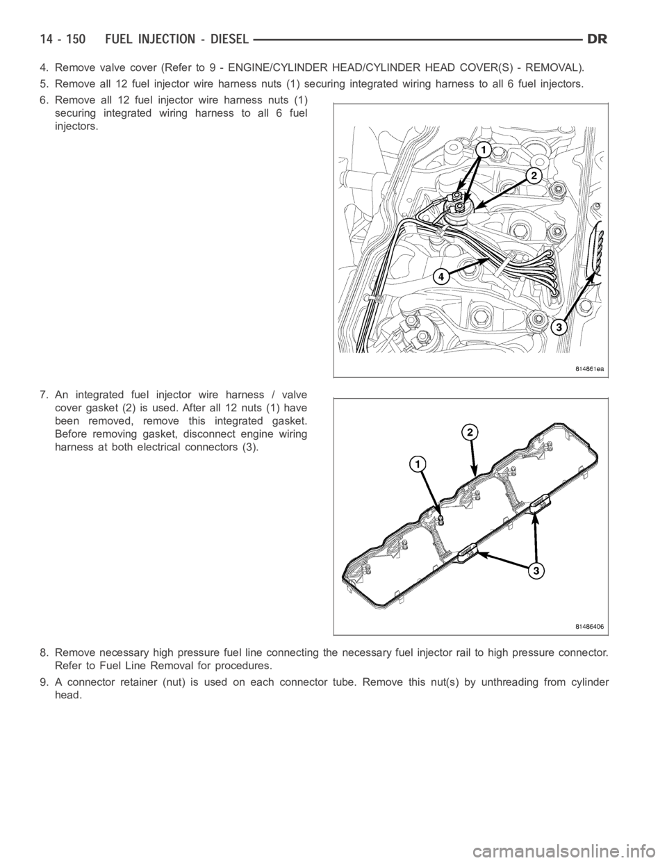
4. Remove valve cover (Refer to 9 - ENGINE/CYLINDER HEAD/CYLINDER HEAD COVER(S) - REMOVAL).
5. Remove all 12 fuel injector wire harness nuts (1) securing integrated wiring harness to all 6 fuel injectors.
6. Remove all 12 fuel injector wire harness nuts (1)
securing integrated wiring harness to all 6 fuel
injectors.
7. An integrated fuel injector wire harness / valve
cover gasket (2) is used. After all 12 nuts (1) have
been removed, remove this integrated gasket.
Before removing gasket, disconnect engine wiring
harness at both electrical connectors (3).
8. Remove necessary high pressure fuel line connecting the necessary fuelinjector rail to high pressure connector.
Refer to Fuel Line Removal for procedures.
9. A connector retainer (nut) is used on each connector tube. Remove this nut(s) by unthreading from cylinder
head.
Page 2388 of 5267
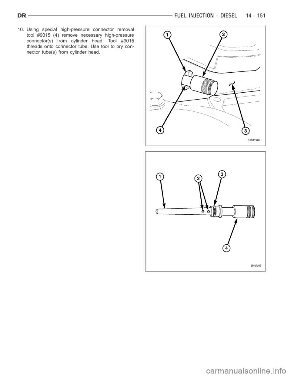
10. Using special high-pressure connector removal
tool #9015 (4) remove necessary high-pressure
connector(s) from cylinder head. Tool #9015
threads onto connector tube. Use tool to pry con-
nector tube(s) from cylinder head.
Page 2389 of 5267
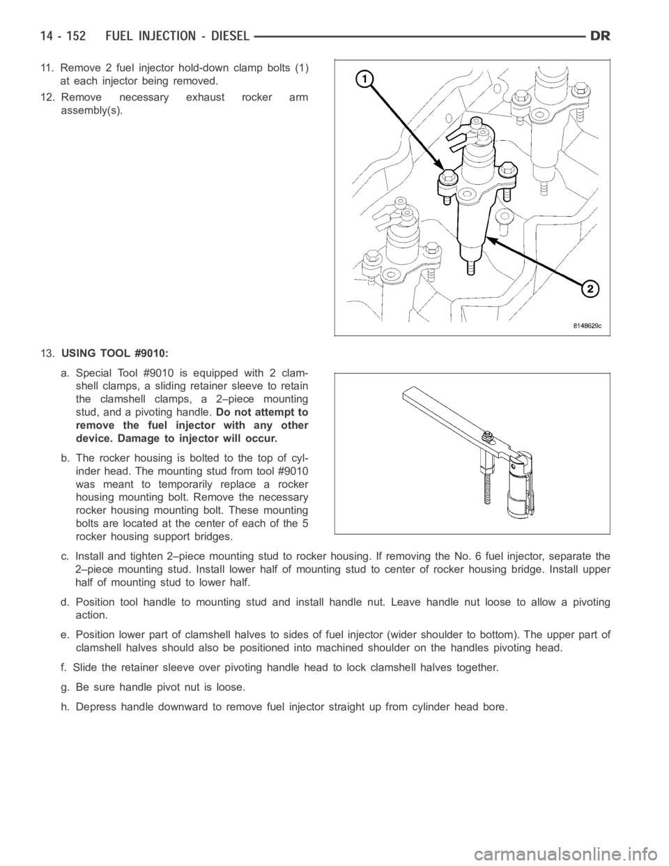
11. Remove 2 fuel injector hold-down clamp bolts (1)
at each injector being removed.
12. Remove necessary exhaust rocker arm
assembly(s).
13.USING TOOL #9010:
a. Special Tool #9010 is equipped with 2 clam-
shell clamps, a sliding retainer sleeve to retain
the clamshell clamps, a 2–piece mounting
stud, and a pivoting handle.Do not attempt to
remove the fuel injector with any other
device. Damage to injector will occur.
b. The rocker housing is bolted to the top of cyl-
inder head. The mounting stud from tool #9010
was meant to temporarily replace a rocker
housing mounting bolt. Remove the necessary
rocker housing mounting bolt. These mounting
bolts are located at the center of each of the 5
rocker housing support bridges.
c. Install and tighten 2–piece mounting stud to rocker housing. If removing the No. 6 fuel injector, separate the
2–piece mounting stud. Install lower half of mounting stud to center of rocker housing bridge. Install upper
half of mounting stud to lower half.
d. Position tool handle to mounting stud and install handle nut. Leave handle nut loose to allow a pivoting
action.
e. Position lower part of clamshell halves to sides of fuel injector (widershoulder to bottom). The upper part of
clamshell halves should also be positioned into machined shoulder on the handles pivoting head.
f. Slide the retainer sleeve over pivoting handle head to lock clamshell halves together.
g. Be sure handle pivot nut is loose.
h. Depress handle downward to remove fuel injector straight up from cylinder head bore.
Page 2390 of 5267
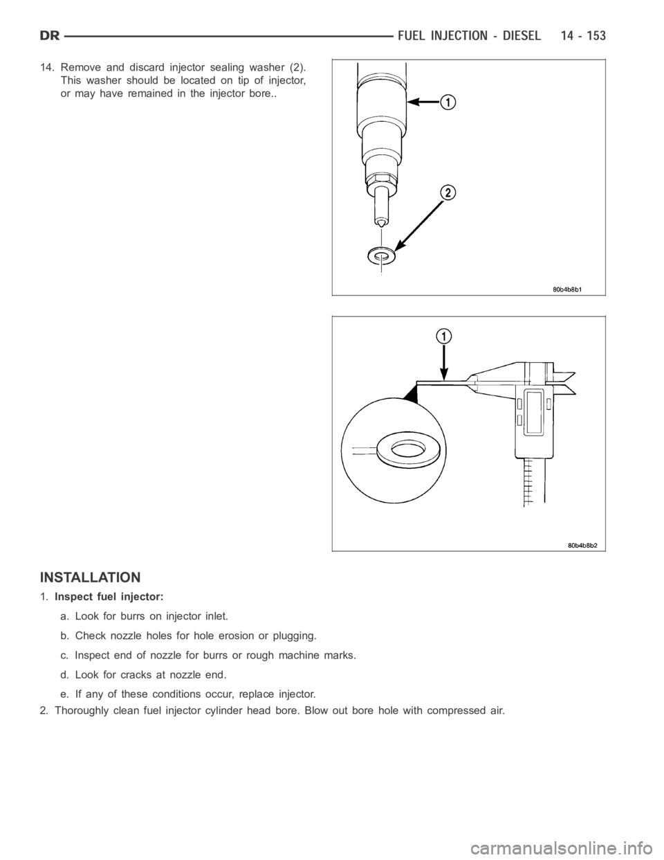
14. Remove and discard injector sealing washer (2).
This washer should be located on tip of injector,
or may have remained in the injector bore..
INSTALLATION
1.Inspect fuel injector:
a. Look for burrs on injector inlet.
b. Check nozzle holes for hole erosion or plugging.
c. Inspect end of nozzle for burrs or rough machine marks.
d. Look for cracks at nozzle end.
e. If any of these conditions occur, replace injector.
2. Thoroughly clean fuel injector cylinder head bore. Blow out bore hole with compressed air.