DODGE RAM SRT-10 2006 Service Repair Manual
Manufacturer: DODGE, Model Year: 2006, Model line: RAM SRT-10, Model: DODGE RAM SRT-10 2006Pages: 5267, PDF Size: 68.7 MB
Page 2411 of 5267
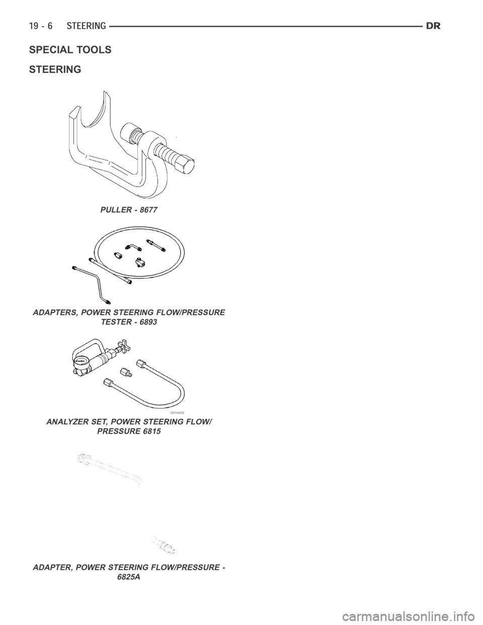
SPECIAL TOOLS
STEERING
PULLER - 8677
ADAPTERS, POWER STEERING FLOW/PRESSURE
TESTER - 6893
ANALYZER SET, POWER STEERING FLOW/
PRESSURE 6815
ADAPTER, POWER STEERING FLOW/PRESSURE -
6825A
Page 2412 of 5267
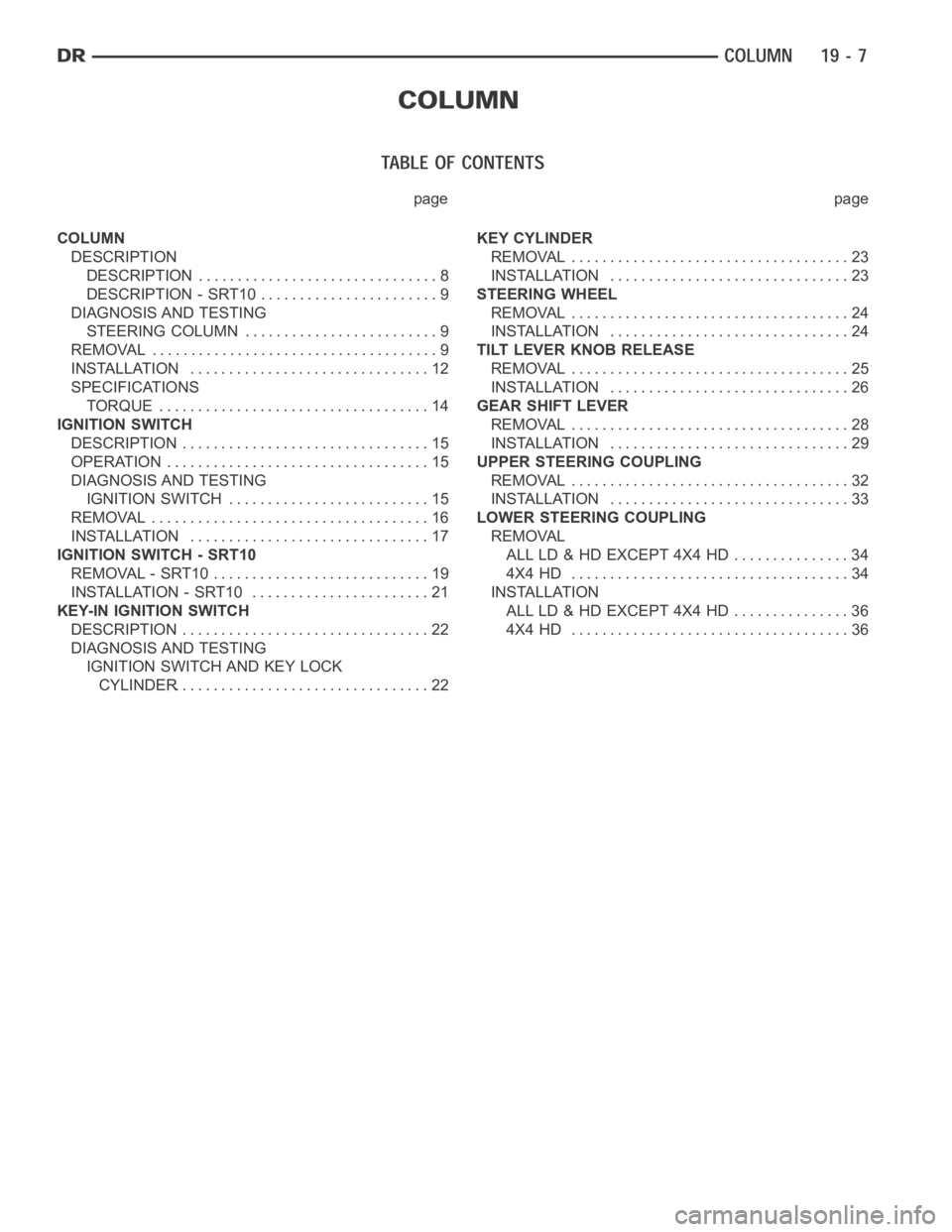
page page
COLUMN
DESCRIPTION
DESCRIPTION ............................... 8
DESCRIPTION - SRT10 ....................... 9
DIAGNOSIS AND TESTING
STEERING COLUMN ......................... 9
REMOVAL ..................................... 9
INSTALLATION ............................... 12
SPECIFICATIONS
TORQUE ................................... 14
IGNITION SWITCH
DESCRIPTION ................................ 15
OPERATION .................................. 15
DIAGNOSIS AND TESTING
IGNITION SWITCH .......................... 15
REMOVAL .................................... 16
INSTALLATION ............................... 17
IGNITION SWITCH - SRT10
REMOVAL - SRT10 ............................ 19
INSTALLATION - SRT10 ....................... 21
KEY-IN IGNITION SWITCH
DESCRIPTION ................................ 22
DIAGNOSIS AND TESTING
IGNITION SWITCH AND KEY LOCK
CYLINDER................................. 22KEY CYLINDER
REMOVAL .................................... 23
INSTALLATION ............................... 23
STEERING WHEEL
REMOVAL .................................... 24
INSTALLATION ............................... 24
TILT LEVER KNOB RELEASE
REMOVAL .................................... 25
INSTALLATION ............................... 26
GEAR SHIFT LEVER
REMOVAL .................................... 28
INSTALLATION ............................... 29
UPPER STEERING COUPLING
REMOVAL .................................... 32
INSTALLATION ............................... 33
LOWER STEERING COUPLING
REMOVAL
ALL LD & HD EXCEPT 4X4 HD ............... 34
4X4 HD .................................... 34
INSTALLATION
ALL LD & HD EXCEPT 4X4 HD ............... 36
4X4 HD .................................... 36
Page 2413 of 5267
COLUMN
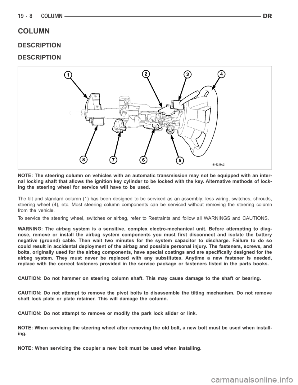
DESCRIPTION
DESCRIPTION
NOTE: The steering column on vehicles with an automatic transmission may not be equipped with an inter-
nal locking shaft that allows the ignition key cylinder to be locked with the key. Alternative methods of lock-
ing the steering wheel for service will have to be used.
The tilt and standard column (1) has been designed to be serviced as an assembly; less wiring, switches, shrouds,
steering wheel (4), etc. Most steering column components can be serviced without removing the steering column
from the vehicle.
To service the steering wheel, switches or airbag, refer to Restraints andfollow all WARNINGS and CAUTIONS.
WARNING: The airbag system is a sensitive, complex electro-mechanical unit. Before attempting to diag-
nose, remove or install the airbag system components you must first disconnect and isolate the battery
negative (ground) cable. Then wait two minutes for the system capacitor todischarge. Failure to do so
could result in accidental deployment of the airbag and possible personalinjury. The fasteners, screws, and
bolts, originally used for the airbag components, have special coatings and are specifically designed for the
airbag system. They must never be replaced with any substitutes. Anytime anew fastener is needed,
replace with the correct fasteners provided in the service package or fasteners listed in the parts books.
CAUTION: Do not hammer on steering column shaft. This may cause damage to the shaft or bearing.
CAUTION: Do not attempt to remove the pivot bolts to disassemble the tilting mechanism. Do not remove
shaft lock plate or plate retainer. This will damage the column.
CAUTION: Do not attempt to remove or modify the park lock slider or link.
NOTE: When servicing the steering wheel after removing the old bolt, a new bolt must be used when install-
ing.
NOTE: When servicing the coupler a new bolt must be used when installing.
Page 2414 of 5267
DESCRIPTION - SRT10
The SRT-10 column has noSTARTposition on the key cylinder. The push starter button switch is mounted on the
Instrument panel center stack. All SRT-10 columns are Tilt columns, Standard cab trucks come with manual trans-
missions, Quad cab trucks come equipped with automatic transmissions.
DIAGNOSIS AND TESTING
STEERING COLUMN
If the vehicle is involved in a front end collision/the air bag has deployedthe column must be inspected. This
inspection will determine if the Column has collapsed. Inspect the columnmounting capsules visually and manually
push and pull them to check for separation or fractures. If capsules are fractured or have moved the column MUST
be replaced.
REMOVAL
WARNING: Before servicing the steering column the airbag system must be disarmed. Refer to electrical
restraint system for service procedures. Failure to do so may result in accidental deployment of the airbag
and possible personal injury.
CAUTION: All fasteners must be torqued to specification to ensure proper operation of the steering column.
1. Position the front wheelsstraight ahead.
2. Disconnect the negative (ground) cable from the battery.
3. Remove the airbag, (Refer to 8 - ELECTRICAL/RE-
STRAINTS/DRIVER AIRBAG - REMOVAL).
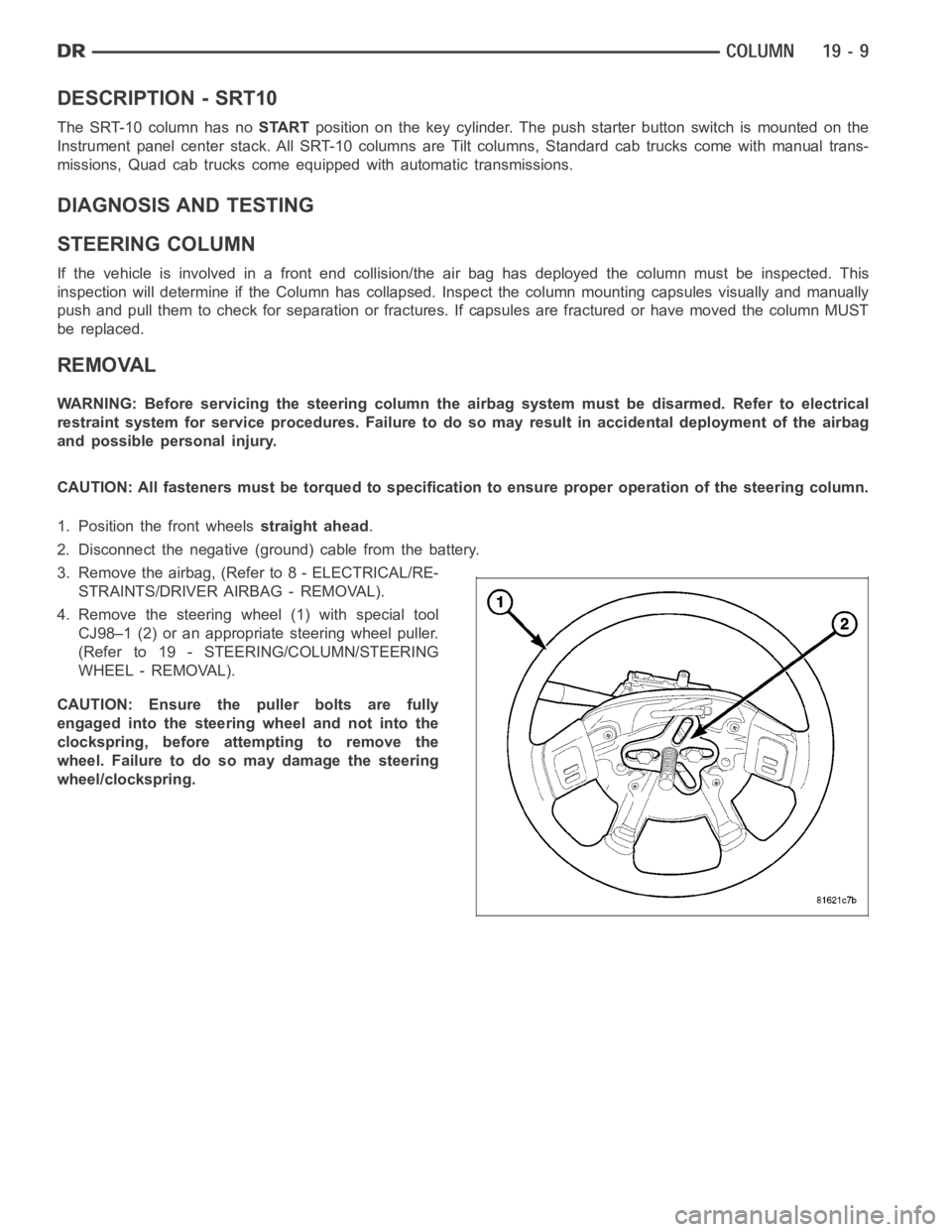
4. Remove the steering wheel (1) with special tool
CJ98–1 (2) or an appropriate steering wheel puller.
(Refer to 19 - STEERING/COLUMN/STEERING
WHEEL - REMOVAL).
CAUTION: Ensure the puller bolts are fully
engaged into the steering wheel and not into the
clockspring, before attempting to remove the
wheel. Failure to do so may damage the steering
wheel/clockspring.
Page 2415 of 5267
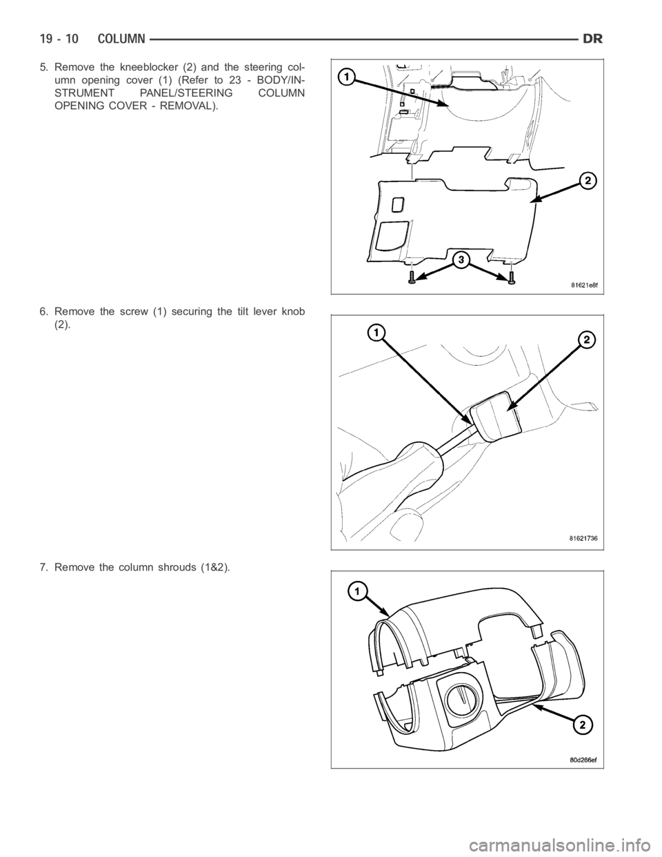
5. Remove the kneeblocker (2) and the steering col-
umn opening cover (1) (Refer to 23 - BODY/IN-
STRUMENT PANEL/STEERING COLUMN
OPENING COVER - REMOVAL).
6. Remove the screw (1) securing the tilt lever knob
(2).
7. Remove the column shrouds (1&2).
Page 2416 of 5267
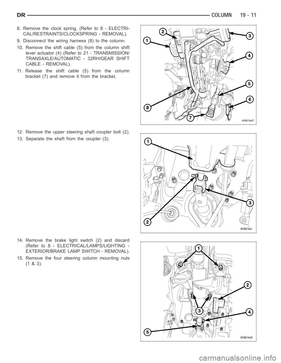
8. Remove the clock spring, (Refer to 8 - ELECTRI-
CAL/RESTRAINTS/CLOCKSPRING - REMOVAL).
9. Disconnect the wiring harness (8) to the column.
10. Remove the shift cable (5) from the column shift
lever actuator (4) (Refer to 21 - TRANSMISSION/
TRANSAXLE/AUTOMATIC - 32RH/GEAR SHIFT
CABLE - REMOVAL).
11. Release the shift cable (5) from the column
bracket (7) and remove it from the bracket.
12. Remove the upper steering shaft coupler bolt (2).
13. Separate the shaft from the coupler (3).
14. Remove the brake light switch (2) and discard
(Refer to 8 - ELECTRICAL/LAMPS/LIGHTING -
EXTERIOR/BRAKE LAMP SWITCH - REMOVAL).
15. Remove the four steering column mounting nuts
(1 & 3).
Page 2417 of 5267
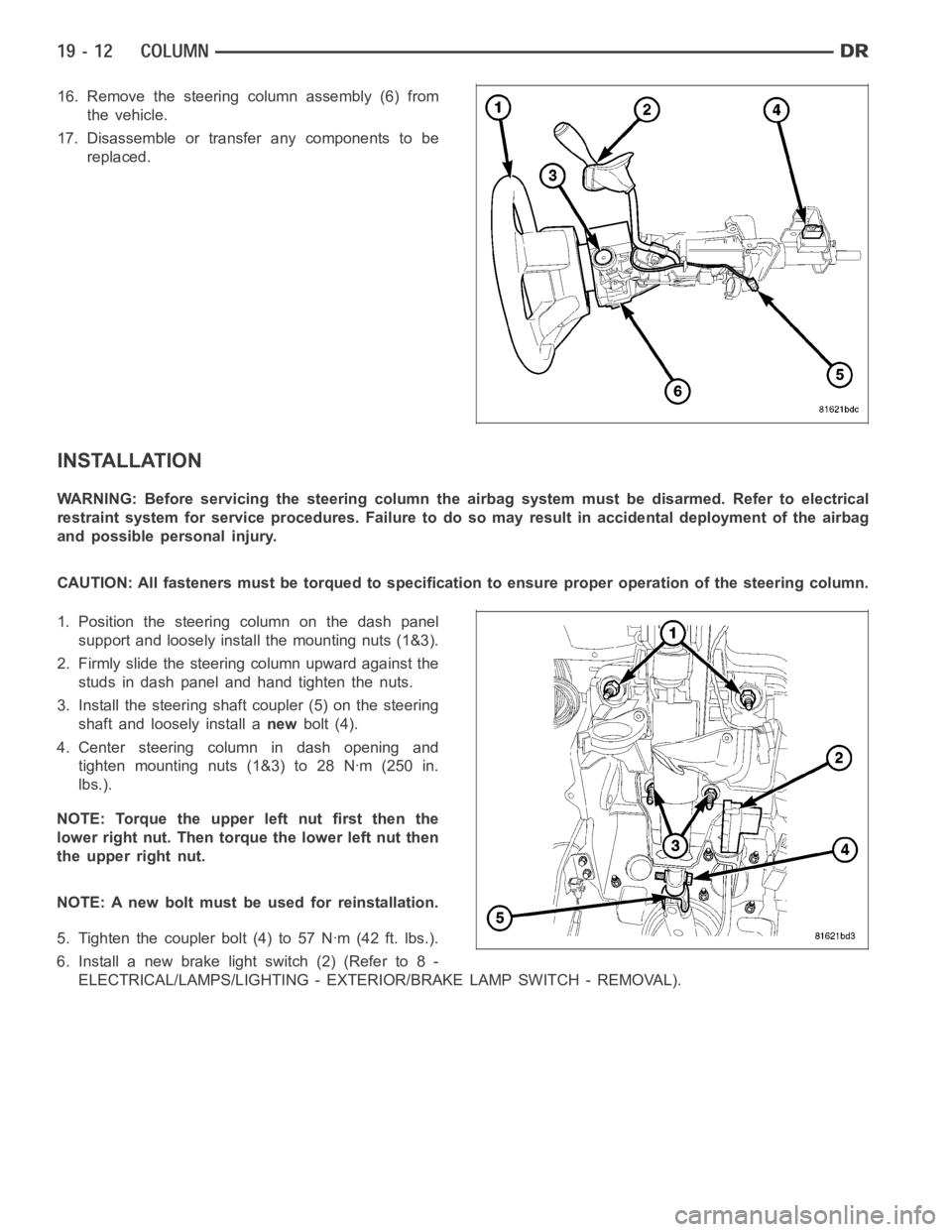
16. Remove the steering column assembly (6) from
the vehicle.
17. Disassemble or transfer any components to be
replaced.
INSTALLATION
WARNING: Before servicing the steering column the airbag system must be disarmed. Refer to electrical
restraint system for service procedures. Failure to do so may result in accidental deployment of the airbag
and possible personal injury.
CAUTION: All fasteners must be torqued to specification to ensure proper operation of the steering column.
1. Position the steering column on the dash panel
support and loosely install the mounting nuts (1&3).
2. Firmly slide the steering column upward against the
studs in dash panel and hand tighten the nuts.
3. Install the steering shaft coupler (5) on the steering
shaft and loosely install anewbolt (4).
4. Center steering column in dash opening and
tighten mounting nuts (1&3) to 28 Nꞏm (250 in.
lbs.).
NOTE: Torque the upper left nut first then the
lower right nut. Then torque the lower left nut then
the upper right nut.
NOTE: A new bolt must be used for reinstallation.
5. Tighten the coupler bolt (4) to 57 Nꞏm (42 ft. lbs.).
6. Install a new brake light switch (2) (Refer to 8 -
ELECTRICAL/LAMPS/LIGHTING - EXTERIOR/BRAKE LAMP SWITCH - REMOVAL).
Page 2418 of 5267
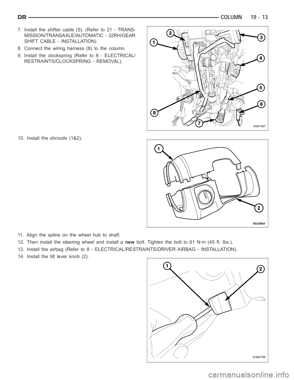
7. Install the shifter cable (5). (Refer to 21 - TRANS-
MISSION/TRANSAXLE/AUTOMATIC - 32RH/GEAR
SHIFT CABLE - INSTALLATION)
8. Connect the wiring harness (8) to the column.
9. Install the clockspring (Refer to 8 - ELECTRICAL/
RESTRAINTS/CLOCKSPRING - REMOVAL).
10. Install the shrouds (1&2).
11. Align the spline on the wheel hub to shaft.
12. Then install the steering wheel and install anewbolt. Tighten the bolt to 61 Nꞏm (45 ft. lbs.).
13. Install the airbag (Refer to 8 - ELECTRICAL/RESTRAINTS/DRIVER AIRBAG- INSTALLATION).
14. Install the tilt lever knob (2).
Page 2419 of 5267
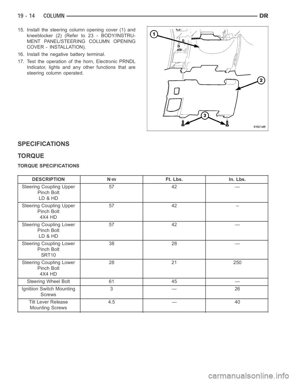
15. Install the steering column opening cover (1) and
kneeblocker (2) (Refer to 23 - BODY/INSTRU-
MENT PANEL/STEERING COLUMN OPENING
COVER - INSTALLATION).
16. Install the negative battery terminal.
17. Test the operation of the horn, Electronic PRNDL
Indicator, lights and any other functions that are
steering column operated.
SPECIFICATIONS
TORQUE
TORQUE SPECIFICATIONS
DESCRIPTION Nꞏm Ft. Lbs. In. Lbs.
Steering Coupling Upper
Pinch Bolt
LD & HD57 42 —
Steering Coupling Upper
Pinch Bolt
4X4 HD57 42 –
Steering Coupling Lower
Pinch Bolt
LD & HD57 42 —
Steering Coupling Lower
Pinch Bolt
SRT1038 28 —
Steering Coupling Lower
Pinch Bolt
4X4 HD28 21 250
Steering Wheel Bolt 61 45 —
Ignitiion Switch Mounting
Screws3—26
Tilt Lever Release
Mounting Screws4.5 — 40
Page 2420 of 5267
IGNITION SWITCH
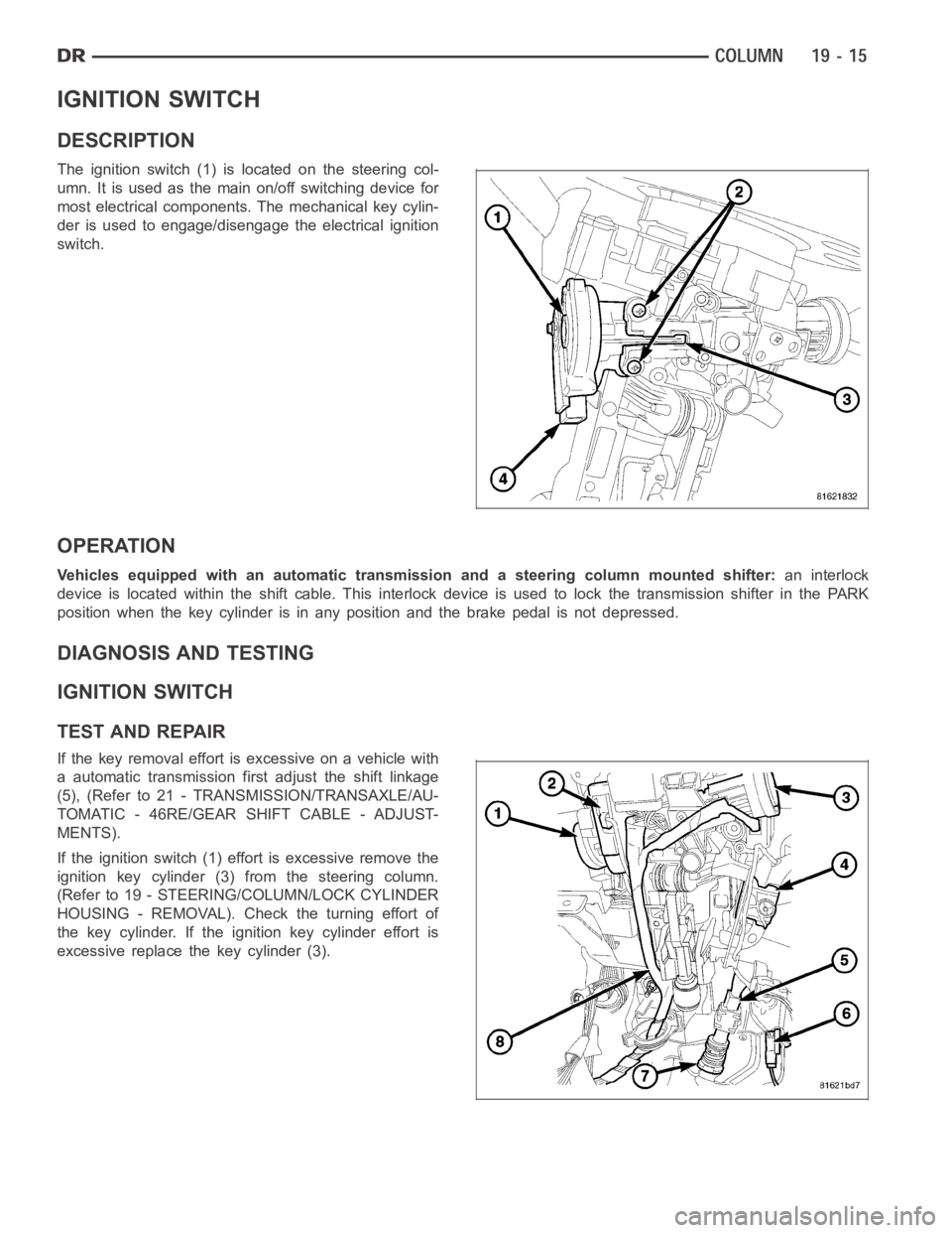
DESCRIPTION
The ignition switch (1) is located on the steering col-
umn. It is used as the main on/off switching device for
most electrical components. The mechanical key cylin-
der is used to engage/disengage the electrical ignition
switch.
OPERATION
Vehicles equipped with an automatic transmission and a steering column mounted shifter:an interlock
device is located within the shift cable. This interlock device is used to lock the transmission shifter in the PARK
position when the key cylinder is in any position and the brake pedal is not depressed.
DIAGNOSIS AND TESTING
IGNITION SWITCH
TEST AND REPAIR
If the key removal effort is excessive on a vehicle with
a automatic transmission first adjust the shift linkage
(5), (Refer to 21 - TRANSMISSION/TRANSAXLE/AU-
TOMATIC - 46RE/GEAR SHIFT CABLE - ADJUST-
MENTS).
If the ignition switch (1) effort is excessive remove the
ignition key cylinder (3) from the steering column.
(Refer to 19 - STEERING/COLUMN/LOCK CYLINDER
HOUSING - REMOVAL). Check the turning effort of
the key cylinder. If the ignition key cylinder effort is
excessive replace the key cylinder (3).