warning light DODGE RAM SRT-10 2006 Service Owner's Guide
[x] Cancel search | Manufacturer: DODGE, Model Year: 2006, Model line: RAM SRT-10, Model: DODGE RAM SRT-10 2006Pages: 5267, PDF Size: 68.7 MB
Page 5071 of 5267

REMOVAL
WARNING: On vehicles equipped with airbags, disable the airbag system before attempting any steering
wheel, steering column, or instrument panel component diagnosis or service. Disconnect and isolate the
battery negative (ground) cable, then wait two minutes for the airbag system capacitor to discharge before
performing further diagnosis or service. This is the only sure way to disable the airbag system. Failure to
take the proper precautions could result in accidental airbag deploymentand possible personal injury or
death.
1. Disconnect and isolate the negative battery cable.
2. Remove the glove box from the instrument panel
(Refer to 23 - BODY/INSTRUMENT PANEL/
GLOVE BOX - REMOVAL).
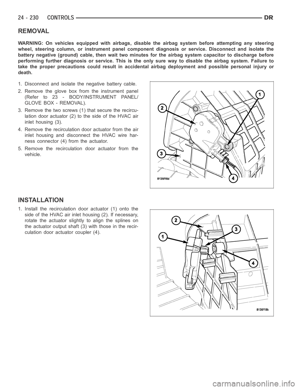
3. Remove the two screws (1) that secure the recircu-
lation door actuator (2) to the side of the HVAC air
inlet housing (3).
4. Remove the recirculation door actuator from the air
inlet housing and disconnect the HVAC wire har-
ness connector (4) from the actuator.
5. Remove the recirculation door actuator from the
vehicle.
INSTALLATION
1. Install the recirculation door actuator (1) onto the
side of the HVAC air inlet housing (2). If necessary,
rotate the actuator slightly to align the splines on
the actuator output shaft (3) with those in the recir-
culation door actuator coupler (4).
Page 5127 of 5267

PLUMBING
DESCRIPTION
The A/C refrigerant lines and hoses are used to carry the refrigerant between the various A/C system components.
The refrigerant lines and hoses for the R-134a system on this vehicle consist of a barrier-hose design with a nylon
tube sandwiched between rubber layers. The nylon tube helps to contain theR-134a refrigerant, which has a
smaller molecular structure than R-12 refrigerant. The ends of the refrigerant lines are made from lightweight alu-
minum or steel, and commonly use braze-less fittings.
Any kinks or sharp bends in the refrigerant lines and hoses will reduce the capacity of the entire A/C system and
can reduce the flow of refrigerant in the system. The radius of all bends in the flexible hose refrigerant lines should
be at least ten times the diameter of the hose and the refrigerant lines should be routed so they are at least 80
millimeters (3 inches) away from the exhaust manifold(s) and exhaust pipe(s).
OPERATION
High pressures are produced in the refrigerant system when the A/C compressor is operating. Extreme care must
be exercised to make sure that each of the refrigerant system connections is pressure-tight and leak free. It is a
good practice to inspect all flexible hose refrigerant lines at least oncea year to make sure they are in good con-
dition and properly routed.
The refrigerant lines and hoses are coupled to other A/C system componentswith block-type fittings. An O-ring seal,
or a flat steel gasket with an integral O-ring (dual plane seal), is used to mate the refrigerant line fittings with A/C
system components to ensure the integrity of the refrigerant system.
The refrigerant lines and hoses cannot be repaired and, if faulty or damaged, they must be replaced.
WARNING
WARNING: The A/C system contains refrigerant under high pressure. Repairs should only be performed by
qualified service personnel. Severe personal injury or death may result from improper service procedures.
WARNING: Avoid breathing the refrigerant and refrigerant oil vapor or mist. Exposure may irritate the eyes,
nose, and/or throat. Wear eye protection when servicing the A/C refrigerant system. Serious eye injury can
result from direct contact with the refrigerant. If eye contact occurs, seek medical attention immediately.
WARNING: Do not expose the refrigerant to open flame. Poisonous gas is createdwhenrefrigerantis
burned. An electronic leak detector is recommended. Severe personal injury or death may result from
improper service procedures.
WARNING: If accidental system discharge occurs, ventilate the work area before resuming service. Large
amounts of refrigerant released in a closed work area will displace the oxygen and cause suffocation and
death.
WARNING: The evaporation rate of R-134a refrigerant at average temperature and altitude is extremely high.
As a result, anything that comes in contact with the refrigerant will freeze. Always protect the skin or del-
icate objects from direct contact with the refrigerant.
WARNING: The R-134a service equipment or the vehicle refrigerant system should not be pressure tested or
leak tested with compressed air. Some mixtures of air and R-134a have been shown to be combustible at
elevated pressures. These mixtures are potentially dangerous, and may result in fire or explosion causing
property damage, personal injury or death.
Page 5171 of 5267

LINE-A/C LIQUID
DESCRIPTION
The liquid line is the refrigerant line that carries refrigerant from the A/C condenser to the A/C evaporator. The liquid
line for this model consist of two separate lines that connect to each otherusing a spring-lock type refrigerant line
coupler (Refer to 24 - HEATING & AIR CONDITIONING/PLUMBING/REFRIGERANT LINE COUPLER - DESCRIP-
TION). The liquid lines are made from light-weight aluminum, and use braze-less fittings.
The front half of the liquid line includes the high-side service port and the rear half of the liquid line contains the
fixed orifice tube.
CAUTION: Use only O-ring seals specified for the vehicle. Failure to use the correct O-ring seal will cause
the refrigerant system connections to leak.
The liquid line has no serviceable parts except for the rubber O-ring seals, high-side service port valve, cap and
secondary retaining clip. The O-ring seals used on the connections are made from a special type of rubber not
affected by R-134a refrigerant. The O-ring seals must be replaced whenever the liquid line is removed and installed.
If the liquid line is found to be leaking or is damaged, it must be replaced.
REMOVAL
3.7L/4.7L/5.7L/5.9L ENGINES
WARNING: Refer to the applicable warnings and cautions for this system before performing the following
operation (Refer to 24 - HEATING & AIR CONDITIONING/PLUMBING - WARNINGS) and (Refer to 24 - HEAT-
ING & AIR CONDITIONING/PLUMBING - CAUTIONS). Failure to follow the warnings and cautions could result
in possible personal injury or death.
NOTE:TheA/Cliquidlineisservicedintwosections.
FRONT SECTION
1. Recover the refrigerant from the refrigerant system
(Refer to 24 - HEATING & AIR CONDITIONING/
PLUMBING - STANDARD PROCEDURE -
REFRIGERANT SYSTEM RECOVERY).
2. Disconnect and isolate the negative battery cable.
3. If equipped with the diesel engine, remove the pas-
senger side battery (Refer to 8 - ELECTRICAL/
BATTERY SYSTEM/BATTERY - REMOVAL).
4. If equipped with a gasoline engine, remove the air
filter housing and mounting bracket (Refer to 9 -
ENGINE/AIR INTAKE SYSTEM/AIR FILTER
HOUSING - REMOVAL).
5. Remove the plastic cover from the condenser out-
let stud.
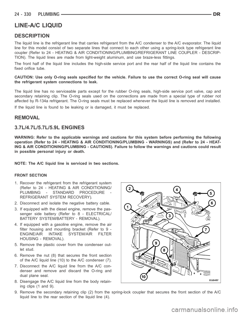
6. Remove the nut (8) that secures the front section
of the A/C liquid line (10) to the A/C condenser (7).
7. Disconnect the A/C liquid line from the A/C con-
denser and remove and discard the O-ring and
dual plane seal.
8. Disengage the A/C liquid line from the body retain-
ing clips (1 and 9).
9. Remove the secondary retaining clip (2) from the spring-lock coupler that secures the front section of the A/C
liquid line to the rear section of the liquid line (4).
Page 5191 of 5267

TUBE-A/C ORIFICE
DESCRIPTION
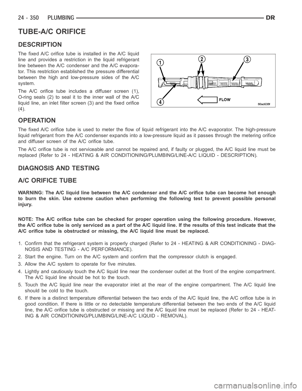
The fixed A/C orifice tube is installed in the A/C liquid
line and provides a restriction in the liquid refrigerant
line between the A/C condenser and the A/C evapora-
tor. This restriction established the pressure differential
between the high and low-pressure sides of the A/C
system.
The A/C orifice tube includes a diffuser screen (1),
O-ring seals (2) to seal it to the inner wall of the A/C
liquid line, an inlet filter screen (3) and the fixed orifice
(4).
OPERATION
The fixed A/C orifice tube is used to meter the flow of liquid refrigerant into the A/C evaporator. The high-pressure
liquid refrigerant from the A/C condenser expands into a low-pressure liquid as it passes through the metering orifice
and diffuser screen of the A/C orifice tube.
The A/C orifice tube is not serviceable and cannot be repaired and, if faulty or plugged, the A/C liquid line must be
replaced (Refer to 24 - HEATING & AIR CONDITIONING/PLUMBING/LINE-A/C LIQUID - DESCRIPTION).
DIAGNOSIS AND TESTING
A/C ORIFICE TUBE
WARNING: The A/C liquid line between the A/C condenser and the A/C orifice tube can become hot enough
to burn the skin. Use extreme caution when performing the following test toprevent possible personal
injury.
NOTE: The A/C orifice tube can be checked for proper operation using the following procedure. However,
the A/C orifice tube is only serviced as a part of the A/C liquid line. If the results of this test indicate that the
A/C orifice tube is obstructed or missing, the A/C liquid line must be replaced.
1. Confirm that the refrigerant system is properly charged (Refer to 24 - HEATING & AIR CONDITIONING - DIAG-
NOSIS AND TESTING - A/C PERFORMANCE).
2. Start the engine. Turn on the A/Csystem and confirm that the compressor clutch is engaged.
3. Allow the A/C system to operate for five minutes.
4. Lightly and cautiously touch the A/C liquid line near the condenser outlet at the front of the engine compartment.
TheA/Cliquidlineshouldbehottothetouch.
5. Touch the A/C liquid line near the evaporator inlet at the rear of the engine compartment. The A/C liquid line
should be cold to the touch.
6. If there is a distinct temperature differential between the two ends of the A/C liquid line, the A/C orifice tube is in
good condition. If there is little or no detectable temperature differential between the two ends of the A/C liquid
line, the A/C orifice tube is obstructed or missing and the A/C liquid line must be replaced (Refer to 24 - HEAT-
ING & AIR CONDITIONING/PLUMBING/LINE-A/C LIQUID - REMOVAL).