Gear ratio DODGE RAM SRT-10 2006 Service Repair Manual
[x] Cancel search | Manufacturer: DODGE, Model Year: 2006, Model line: RAM SRT-10, Model: DODGE RAM SRT-10 2006Pages: 5267, PDF Size: 68.7 MB
Page 28 of 5267
Theory of Operation
The Park Neutral switch rationality test is enabled only for vehicles equipped with a 4/5 speed automatic transmis-
sion. This diagnostic checks if the park/neutral switch is incorrectly stuck in the neutral position during driving con-
ditions by comparing Vehicle Speed, Engine Speed, Throttle Position, andPressure Ratio to the fail thresholds and
by looking at the state of the Park/Neutral Switch. The stuck in drive condition is not explicitly checked as the starter
relay does not energize and therefore render the vehicle inoperable.
When Monitored:
Continuously with the transmission in Park, Neutral, or Drive and NOT in Limp-in mode.
Set Condition:
This code will set if the PCM detects an incorrect Park/Neutral switch state for a given mode of vehicle oper-
ation. One trip fault. Three good trips to turn off the MIL.
Possible Causes
TRS (T41) SENSE (P/N SENSE) CIRCUIT OPEN
TRS (T41) SENSE (P/N SENSE) CIRCUIT SHORTED TO GROUND
TRANSMISSION RANGE SENSOR
PCM
Always perform the Pre-Diagnostic Troubleshooting procedure before proceeding. (Refer to 9 - ENGINE -
DIAGNOSIS AND TESTING).
Diagnostic Test
1.P/N AND D/R NOT IN CORRECT POSITION
NOTE: Check the TCM for DTCs, if P0706 is set in the TCM diagnose the TCM code before continuing.
Ignition on, engine not running.
With the scan tool, read the Park/Neutral Position Switch input state.
While moving the gear selector through all gear positions (Park to 1 and back to Park), monitor the scan tool dis-
play.
Did the scan tool display show P/N and D/R in the correct gear positions?
Ye s>>
Refer to the INTERMITTENT CONDITION Diagnostic Procedure.
Perform the POWERTRAIN VERIFICATION TEST. (Refer to 9 - ENGINE - STANDARD PROCEDURE)
No>>
Go To 2
Page 912 of 5267
P0355-IGNITION COIL #5 PRIMARY
CIRCUIT................................. 1948
P0420-1/1 CATALYTIC CONVERTER
EFFICIENCY............................. 1952
P0432-2/1 CATALYTIC CONVERTER
EFFICIENCY............................. 1955
P0441-EVAP PURGE FLOW MONITOR . . . . . 1958
P0442-EVAP LEAK MONITOR MEDIUM
(0.040) LEAK DETECTED.................. 1962
P0443-EVAP PURGE SOLENOID CIRCUIT . . 1968
P0455-EVAP LEAK MONITOR LARGE LEAK
DETECTED............................... 1972
P0460-FUEL LEVEL SENDING UNIT NO
CHANGE OVER MILES.................... 1978
P0462-FUEL LEVEL SENDING UNIT VOLTS
TOO LOW................................ 1979
P0463-FUEL LEVEL SENSOR 1 CIRCUIT
HIGH.................................... 1982
P0500-NO VEHICLE SPEED SIGNAL ....... 1986
P0505-IDLE AIR CONTROL MOTOR
CIRCUITS................................ 1989
P0513-INVALID SKREEM KEY ............. 1994
P0522-OIL PRESSURE CIRCUIT LOW ...... 1996
P0523-OIL PRESSURE CIRCUIT HIGH ..... 2000
P0601-PCM INTERNAL CONTROLLER
FAILURE................................. 2003
P0622-GENERATOR FIELD NOT
SWITCHING PROPERLY.................. 2004
P0645-A/C CLUTCH RELAY CIRCUIT . . ..... 2008
P0801-REVERSE GEAR LOCKOUT CIRCUIT
OPEN OR SHORTED...................... 2012
P1195-O2 SENSOR 1/1 SLOW DURING
CATALYST MONITOR..................... 2016
P1196-O2 SENSOR 2/1 SLOW DURING
CATALYST MONITOR..................... 2019
P126B-ASD CONTROL CIRCUIT 2 LOW .... 2022
P126C-ASD CONTROL CIRCUIT 2 HIGH .... 2026
P126D-ASD CONTROL CIRCUIT 2 OPEN . . . 2030
P126E-ASD CONTROL CIRCUIT
OVERCURRENT.......................... 2034
P1272-A/C CLUTCH CONTROL CIRCUIT 2
LOW..................................... 2038
P1273-A/C CLUTCH CONTROL CIRCUIT 2
HIGH.................................... 2041
P1274-A/C CLUTCH CONTROL CIRCUIT 2
OPEN.................................... 2045
P1275-A/C CLUTCH CONTROL CIRCUIT 2
OVERCURRENT.......................... 2049
P1277-STARTER CONTROL CIRCUIT 2 LOW
(TIPM)................................... 2052
P1278-STARTER CONTROL CIRCUIT 2
HIGH (TIPM).............................. 2055
P1279-STARTER CONTROL CIRCUIT 2
OPEN (TIPM)............................. 2058
P127A-STARTER CONTROL CIRCUIT 2
OVERCURRENT.......................... 2061
P127C-FUEL PUMP CONTROL CIRCUIT 2
LOW..................................... 2064P127D-FUEL PUMP CONTROL CIRCUIT 2
HIGH.................................... 2067
P127E-FUEL PUMP CONTROL CIRCUIT 2
OPEN (TIPM)............................. 2071
P0127F-FUEL PUMP CONTROL CIRCUIT 2
OVERCURRENT (TIPM)................... 2075
P1281-ENGINE IS COLD TOO LONG ....... 2078
P1282-FUEL PUMP/SYSTEM RELAY
CONTROL CIRCUIT....................... 2079
P1294-TARGET IDLE NOT REACHED ...... 2082
P1296-NO 5-VOLTS TO MAP SENSOR ..... 2085
P1297-NO CHANGE IN MAP FROM START
TO RUN.................................. 2089
P1388-AUTO SHUTDOWN RELAY CONTROL
CIRCUIT................................. 2094
P1389-NO ASD RELAY OUTPUT VOLTAGE
AT P C M.................................. 2097
P1391-INTERMITTENT LOSS OF CMP OR
CKP
..................................... 2100
P1398-MIS-FIRE ADAPTIVE NUMERATOR
AT L I M I T................................. 2104
P1486-EVAP LEAK MONITOR PINCHED
HOSE FOUND............................ 2106
P1492-AMBIENT/BATTERY TEMPERATURE
SENSOR VOLTAGE TOO HIGH............. 2110
P1493-AMBIENT/BATTERY TEMPERATURE
SENSOR VOLTAGE TOO LOW............. 2114
P1494-LEAK DETECTION PUMP SWITCH
OR MECHANICAL FAULT.................. 2117
P1495-LEAK DETECTION PUMP SOLENOID
CIRCUIT................................. 2121
P1499-HYDRAULIC FAN SOLENOID
CIRCUIT................................. 2126
P1594-CHARGING SYSTEM VOLTAGE TOO
HIGH.................................... 2130
P1598-A/C PRESSURE SENSOR VOLTAGE
TOO HIGH............................... 2133
P1599-A/C PRESSURE SENSOR VOLTAGE
TOO LOW................................ 2137
P1682-CHARGING SYSTEM VOLTAGE TOO
LOW..................................... 2141
P1687-NO CLUSTER BUS MESSAGE ...... 2146
P1695-BUS MESSAGE FROM BODY
CONTROL MODULE...................... 2148
P1696-PCM FAILURE EEPROM WRITE
DENIED.................................. 2151
*BRAKE SWITCH SENSE STATUS DOES
NOT CHANGE ON THE SCAN TOOL....... 2153
*CANNOT SHIFT INTO REVERSE .......... 2157
*CHECKING A/C SYSTEM OPERATION
WITH NO DTCS.......................... 2159
*CHECKING CHARGING SYSTEM
OPERATION WITH NO DTCS.............. 2163
*CHECKING RADIATOR FAN OPERATION . . 2167
*CHECKING THE PCM POWER AND
GROUNDS............................... 2169
B2277–CAN GATEWAY INTERNAL
(GATEWAY).............................. 2172
U0001–CAN C BUS CIRCUIT (GATEWAY) . . . 2172
Page 1521 of 5267
2. Position the new cylinder head gasket on the locat-
ing dowels.
CAUTION: When installing cylinder head, use care
not damage the tensioner arm or the guide arm.
3. Position the cylinder head onto the cylinder block.
Make sure the cylinder head seats fully over the
locating dowels.
NOTE: The four smaller cylinder head mounting
bolts require sealant to be added to them before
installing. Failure to do so may cause leaks.
4. Lubricate the cylinder head bolt threads with clean
engine oil and install the eight M11 bolts.
5. Coat the four M8 cylinder head bolts withMopar
Lock and Seal Adhesivethen install the bolts.
NOTE: The cylinder head bolts are tightened using
an angle torque procedure, however, the bolts are
not a torque-to-yield design.
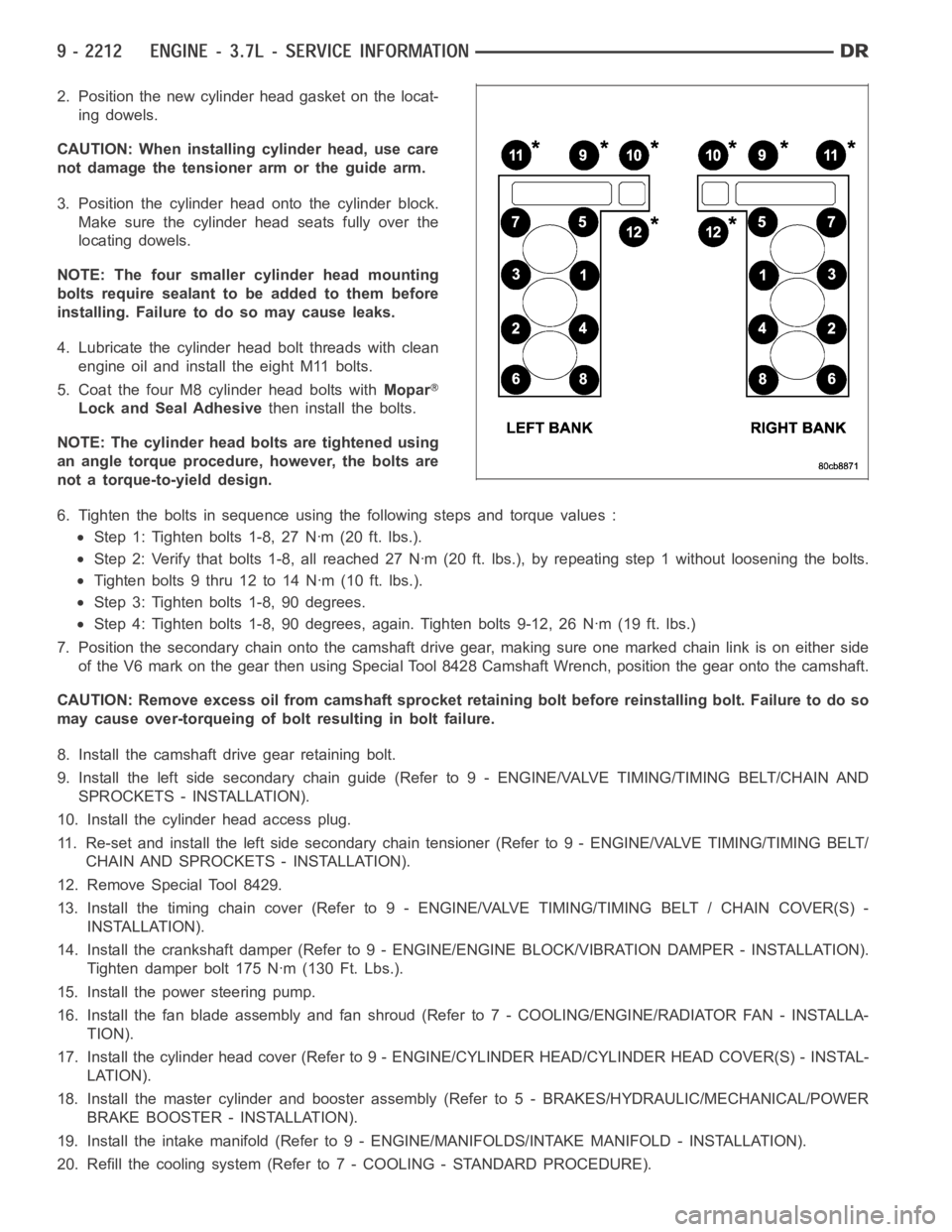
6. Tighten the bolts in sequence using the following steps and torque values:
Step 1: Tighten bolts 1-8, 27 Nꞏm (20 ft. lbs.).
Step 2: Verify that bolts 1-8, all reached 27 Nꞏm (20 ft. lbs.), by repeatingstep 1 without loosening the bolts.
Tightenbolts9thru12to14Nꞏm(10ft.lbs.).
Step 3: Tighten bolts 1-8, 90 degrees.
Step 4: Tighten bolts 1-8, 90 degrees, again. Tighten bolts 9-12, 26 Nꞏm (19ft. lbs.)
7. Position the secondary chain onto the camshaft drive gear, making sure one marked chain link is on either side
of the V6 mark on the gear then using Special Tool 8428 Camshaft Wrench, position the gear onto the camshaft.
CAUTION: Remove excess oil from camshaft sprocket retaining bolt before reinstalling bolt. Failure to do so
may cause over-torqueing of bolt resulting in bolt failure.
8. Install the camshaft drive gear retaining bolt.
9. Install the left side secondary chain guide (Refer to 9 - ENGINE/VALVE TIMING/TIMING BELT/CHAIN AND
SPROCKETS - INSTALLATION).
10. Install the cylinder head access plug.
11. Re-set and install the left side secondary chain tensioner (Refer to 9 -ENGINE/VALVE TIMING/TIMING BELT/
CHAIN AND SPROCKETS - INSTALLATION).
12. Remove Special Tool 8429.
13. Install the timing chain cover (Refer to 9 - ENGINE/VALVE TIMING/TIMING BELT / CHAIN COVER(S) -
INSTALLATION).
14. Install the crankshaft damper (Refer to 9 - ENGINE/ENGINE BLOCK/VIBRATION DAMPER - INSTALLATION).
Tighten damper bolt 175 Nꞏm (130 Ft. Lbs.).
15. Install the power steering pump.
16. Install the fan blade assembly and fan shroud (Refer to 7 - COOLING/ENGINE/RADIATOR FAN - INSTALLA-
TION).
17. Install the cylinder head cover (Refer to 9 - ENGINE/CYLINDER HEAD/CYLINDER HEAD COVER(S) - INSTAL-
LATION).
18. Install the master cylinder and booster assembly (Refer to 5 - BRAKES/HYDRAULIC/MECHANICAL/POWER
BRAKE BOOSTER - INSTALLATION).
19. Install the intake manifold (Refer to 9 - ENGINE/MANIFOLDS/INTAKE MANIFOLD - INSTALLATION).
20. Refill the cooling system (Refer to 7 - COOLING - STANDARD PROCEDURE).
Page 1537 of 5267
12. Verify the V6 mark on the camshaft sprocket is at the 12 o’clock position. Rotate the crankshaft one turn if
necessary.
13. Remove the crankshaft damper (Refer to 9 - ENGINE/ENGINE BLOCK/VIBRATION DAMPER - REMOVAL).
14. Remove the timing chain cover (Refer to 9 - ENGINE/VALVE TIMING/TIMINGBELT / CHAIN COVER(S) -
REMOVAL).
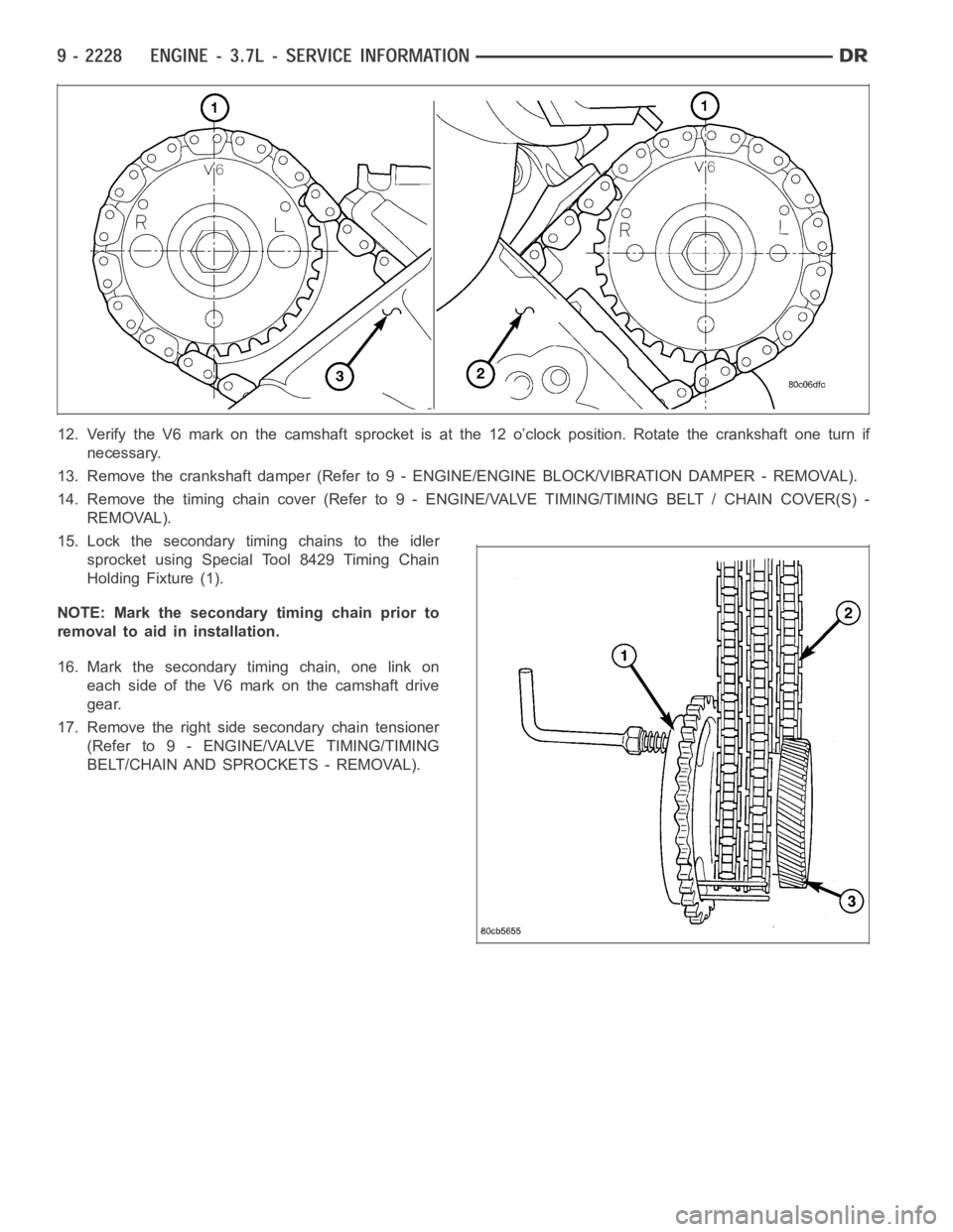
15. Lock the secondary timing chains to the idler
sprocket using Special Tool 8429 Timing Chain
Holding Fixture (1).
NOTE: Mark the secondary timing chain prior to
removal to aid in installation.
16. Mark the secondary timing chain, one link on
each side of the V6 mark on the camshaft drive
gear.
17. Remove the right side secondary chain tensioner
(Refer to 9 - ENGINE/VALVE TIMING/TIMING
BELT/CHAIN AND SPROCKETS - REMOVAL).
Page 1606 of 5267
VALVE TIMING
DESCRIPTION
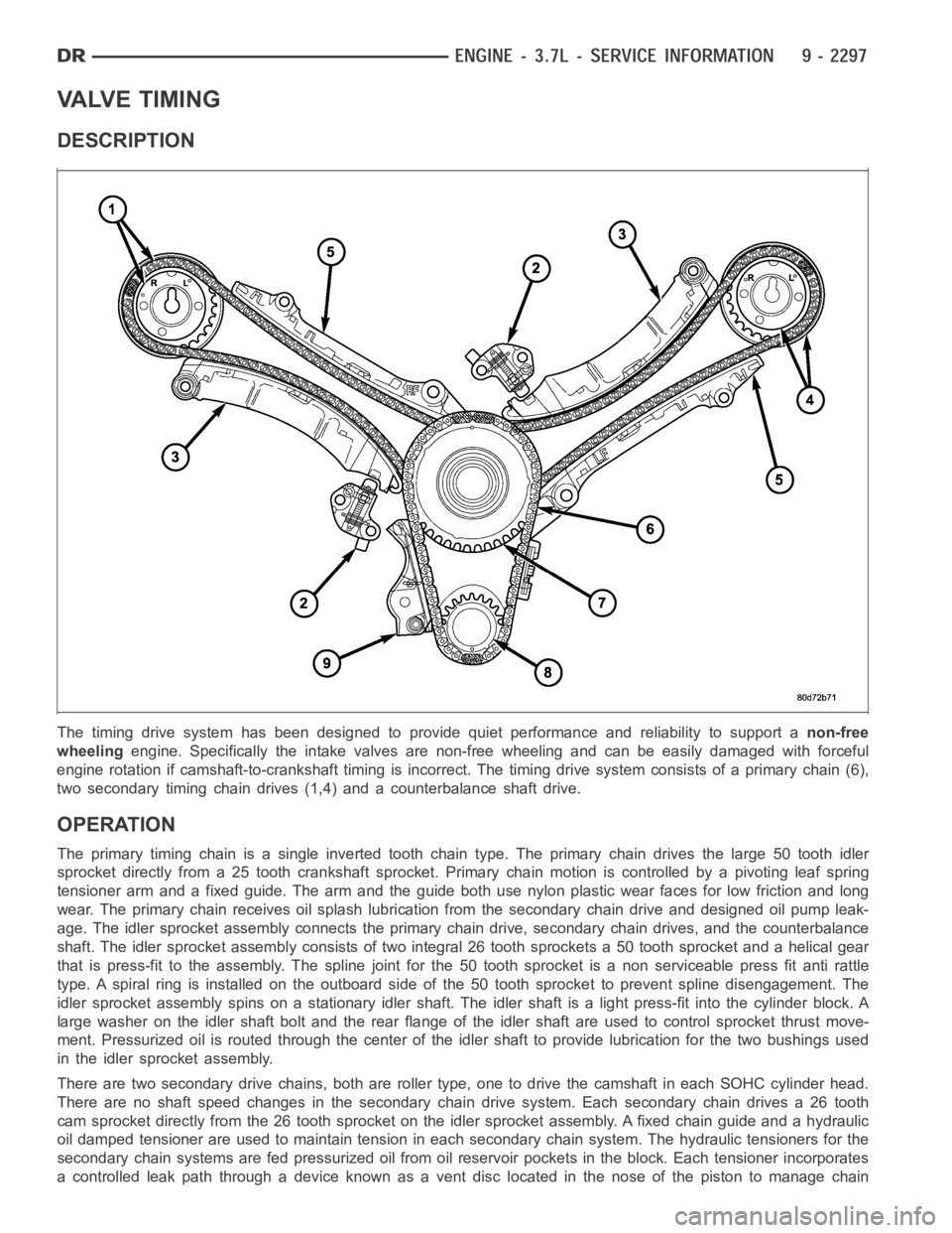
The timing drive system has been designed to provide quiet performance andreliability to support anon-free
wheelingengine. Specifically the intake valves are non-free wheeling and can be easily damaged with forceful
engine rotation if camshaft-to-crankshaft timing is incorrect. The timing drive system consists of a primary chain (6),
two secondary timing chain drives (1,4) and a counterbalance shaft drive.
OPERATION
The primary timing chain is a single inverted tooth chain type. The primarychaindrivesthelarge50toothidler
sprocket directly from a 25 tooth crankshaft sprocket. Primary chain motion is controlled by a pivoting leaf spring
tensioner arm and a fixed guide. The arm and the guide both use nylon plasticwear faces for low friction and long
wear. The primary chain receives oil splash lubrication from the secondary chain drive and designed oil pump leak-
age. The idler sprocket assembly connects the primary chain drive, secondary chain drives, and the counterbalance
shaft. The idler sprocket assembly consists of two integral 26 tooth sprockets a 50 tooth sprocket and a helical gear
that is press-fit to the assembly. Thespline joint for the 50 tooth sprocket is a non serviceable press fit anti rattle
type. A spiral ring is installed on the outboard side of the 50 tooth sprocket to prevent spline disengagement. The
idler sprocket assembly spins on a stationary idler shaft. The idler shaftis a light press-fit into the cylinder block. A
large washer on the idler shaft bolt and the rear flange of the idler shaft are used to control sprocket thrust move-
ment. Pressurized oil is routed through the center of the idler shaft to provide lubrication for the two bushings used
in the idler sprocket assembly.
There are two secondary drive chains, both are roller type, one to drive thecamshaft in each SOHC cylinder head.
There are no shaft speed changes in the secondary chain drive system. Each secondary chain drives a 26 tooth
cam sprocket directly from the 26 tooth sprocket on the idler sprocket assembly. A fixed chain guide and a hydraulic
oil damped tensioner are used to maintain tension in each secondary chain system. The hydraulic tensioners for the
secondary chain systems are fed pressurized oil from oil reservoir pockets in the block. Each tensioner incorporates
a controlled leak path through a device known as a vent disc located in the nose of the piston to manage chain
Page 1658 of 5267
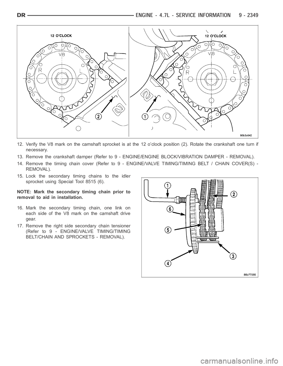
12. Verify the V8 mark on the camshaft sprocket is at the 12 o’clock position(2). Rotate the crankshaft one turn if
necessary.
13. Remove the crankshaft damper (Refer to 9 - ENGINE/ENGINE BLOCK/VIBRATION DAMPER - REMOVAL).
14. Remove the timing chain cover (Refer to 9 - ENGINE/VALVE TIMING/TIMINGBELT / CHAIN COVER(S) -
REMOVAL).
15. Lock the secondary timing chains to the idler
sprocket using Special Tool 8515 (6).
NOTE: Mark the secondary timing chain prior to
removal to aid in installation.
16. Mark the secondary timing chain, one link on
each side of the V8 mark on the camshaft drive
gear.
17. Remove the right side secondary chain tensioner
(Refer to 9 - ENGINE/VALVE TIMING/TIMING
BELT/CHAIN AND SPROCKETS - REMOVAL).
Page 1659 of 5267
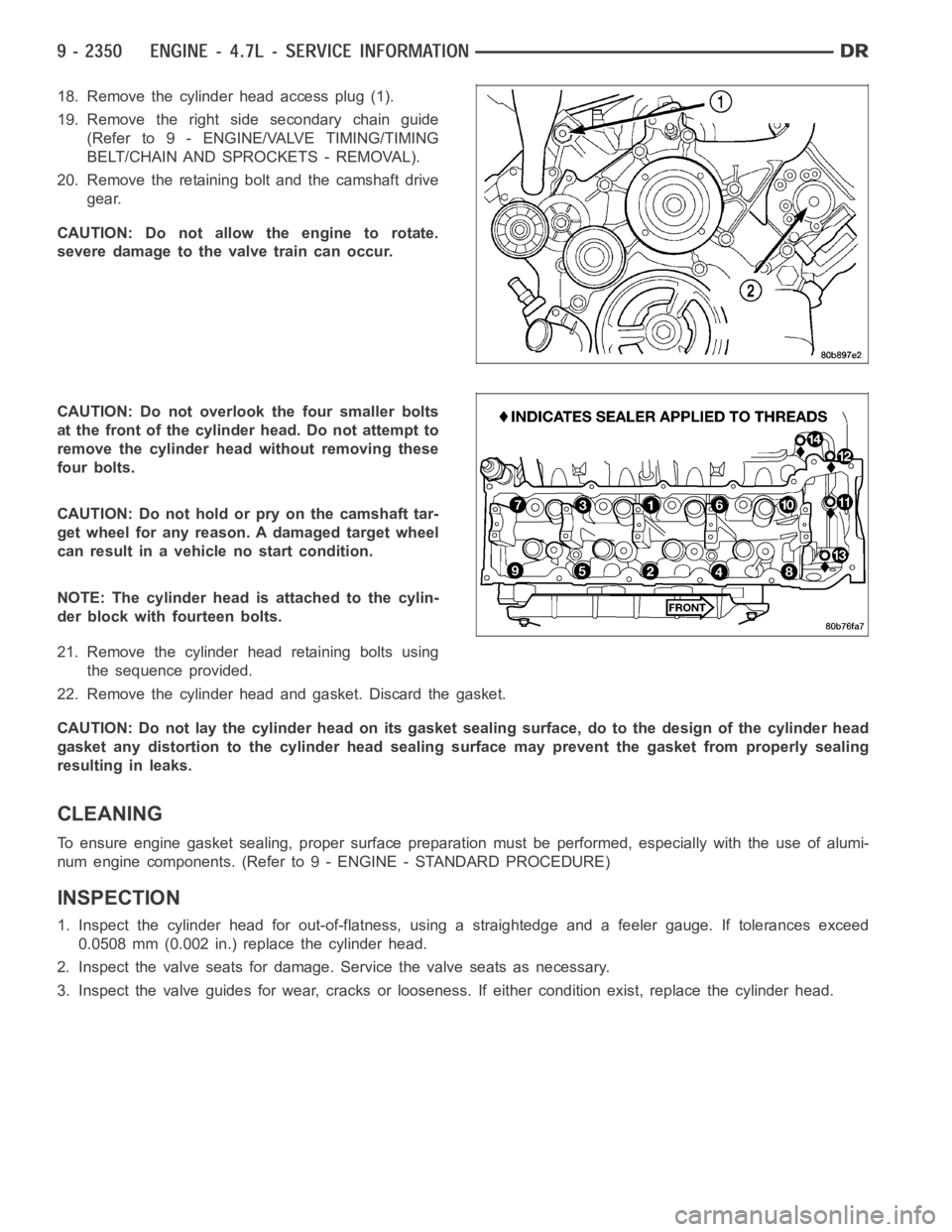
18. Remove the cylinder head access plug (1).
19. Remove the right side secondary chain guide
(Refer to 9 - ENGINE/VALVE TIMING/TIMING
BELT/CHAIN AND SPROCKETS - REMOVAL).
20. Remove the retaining bolt and the camshaft drive
gear.
CAUTION: Do not allow the engine to rotate.
severe damage to the valve train can occur.
CAUTION: Do not overlook the four smaller bolts
at the front of the cylinder head. Do not attempt to
remove the cylinder head without removing these
four bolts.
CAUTION: Do not hold or pry on the camshaft tar-
get wheel for any reason. A damaged target wheel
can result in a vehicle no start condition.
NOTE: The cylinder head is attached to the cylin-
der block with fourteen bolts.
21. Remove the cylinder head retaining bolts using
the sequence provided.
22. Remove the cylinder head and gasket. Discard the gasket.
CAUTION: Do not lay the cylinder head on its gasket sealing surface, do to the design of the cylinder head
gasket any distortion to the cylinder head sealing surface may prevent thegasket from properly sealing
resulting in leaks.
CLEANING
To ensure engine gasket sealing, proper surface preparation must be performed, especially with the use of alumi-
num engine components. (Refer to 9 - ENGINE - STANDARD PROCEDURE)
INSPECTION
1. Inspect the cylinder head for out-of-flatness, using a straightedge and a feeler gauge. If tolerances exceed
0.0508 mm (0.002 in.) replace the cylinder head.
2. Inspect the valve seats for damage. Service the valve seats as necessary.
3. Inspect the valve guides for wear, cracks or looseness. If either condition exist, replace the cylinder head.
Page 1908 of 5267
CONDITION POSSIBLE CAUSES CORRECTION
3. Improperly operating vibration
damper3. Inspect/replace vibration damper.
4. Improperly operating electronically
controlled viscous fan drive.4. Inspect/replace fan drive.
5. Worn or damaged generator
bearing.5. Check/replace generator.
6. Flywheel housing misaligned. 6. Check/correct flywheel alignment.
7. Loose or broken power
component.7. Inspect the crankshaft and rods for
damage that causes an unbalance
condition. Repair/replace as required.
8. Worn or unbalanced driveline
components.8. Check/repair driveline components.
EXCESSIVE ENGINE
NOISES1. Drive belt squeal, insufficient
tension or abnormally high loading.1. Check the automatic tensioner and
inspect the drive belt. Make sure water
pump, tensioner pulley, fan hub, generator
and power steering pump turn freely.
2. Intake air or exhaust leaks. 2. Refer to Excessive Exhaust Smoke
(Refer to 9 - ENGINE - DIAGNOSIS AND
TESTING).
3. Excessive valve lash. 3. Adjust valves. Make sure the push rods
are not bent and rocker arms, adjusting
screws, crossheads, are not severely worn.
Replace bent or severely worn components.
4. Turbocharger noise. 4. Check turbocharger impeller and turbine
wheel for housing contact. Repair/replace
as required.
5. Gear train noise. 5. Visually inspect and measure gear
backlash. Replace gears as required.
6. Power function knock. 6. Check/replace rod and main bearings.
DIAGNOSIS AND TESTING -SMOKE DIAGNOSIS CHARTS
The following charts include possible causes and corrections forexcess or abnormalexhaust smoke. Small
amounts of exhaust smoke (at certain times) are to be considered normal fora diesel powered engine.
EXCESSIVE BLACK SMOKE
POSSIBLE CAUSE CORRECTION
Air filter dirty or plugged. Check Filter Minder
at air filter (Refer to 9 - ENGINE/
AIR INTAKE SYSTEM/AIR CLEANER ELEMENT -
REMOVAL).
Air intake system restricted. Check entire air intake system including all hoses and
tubes for restrictions, collapsed parts or damage.
Repair/replace as necessary.
Air Leak in Intake System. Check entire air intake system (Refer to 11 - EXHAUST
SYSTEM/TURBOCHARGER SYSTEM/CHARGE AIR
COOLER AND PLUMBING - DIAGNOSIS AND
TESTING) including all hoses and tubes for cracks,
loose clamps and/or holes in rubber ducts. Also check
intake manifold for loose mounting hardware.
Diagnostic Trouble Codes (DTC’s) active or multiple,
intermittent DTC’s.Refer to Powertrain Diagnostic Procedures Information.
Page 1954 of 5267
8. Remove the accessory drive belt (Refer to 7 - COOLING/ACCESSORY DRIVE/DRIVE BELTS - REMOVAL).
9. With the damper TDC mark in the 12 o’clock position, add a paint mark anywhere on the gear housing cover
next to the crankshaft damper. Place another mark on the vibration damper in alignment with the mark you just
made on the cover.
10. Divide the crankshaft damper into three equally sized segments as follows:
a. Using a tape measure, measure the circumference of the crankshaft damper and divide the measurement by
three (3).
b. Measure that distance in a counterclockwise direction from the first balancer mark and place another mark
on the balancer.
c. From the second damper mark, again measure in a counterclockwise direction and place a mark on the
damper at the same distance you measured when placing the second damper mark. The damper should
now be marked in three equally spaced locations and the damper TDC mark should be in the 12 o’clock
position.
d. Remove injectors, fuel lines, and high pressure connectors for every cylinder that requires repair.
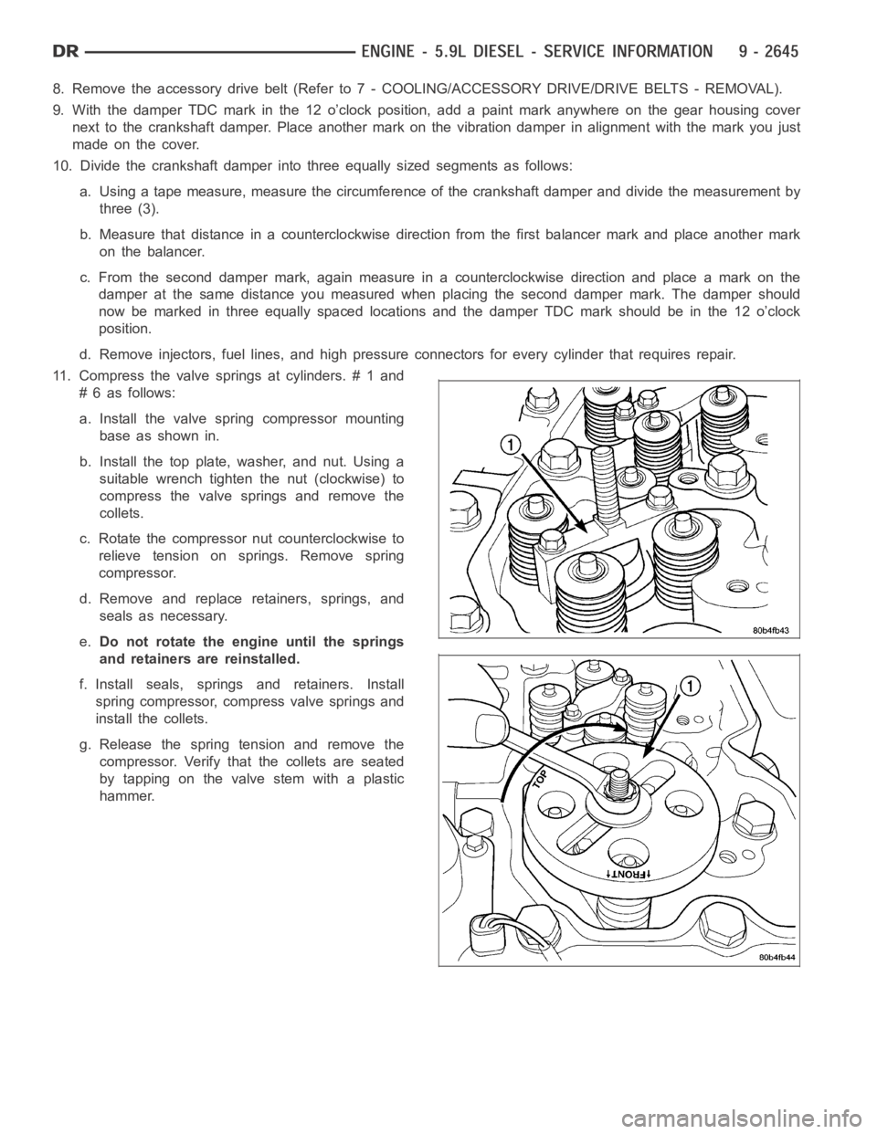
11. Compress the valve springs at cylinders. # 1 and
# 6 as follows:
a. Install the valve spring compressor mounting
base as shown in.
b. Install the top plate, washer, and nut. Using a
suitable wrench tighten the nut (clockwise) to
compress the valve springs and remove the
collets.
c. Rotate the compressor nut counterclockwise to
relieve tension on springs. Remove spring
compressor.
d. Remove and replace retainers, springs, and
seals as necessary.
e.Do not rotate the engine until the springs
and retainers are reinstalled.
f. Install seals, springs and retainers. Install
spring compressor, compress valve springs and
install the collets.
g. Release the spring tension and remove the
compressor. Verify that the collets are seated
by tapping on the valve stem with a plastic
hammer.
Page 1966 of 5267
CAMSHAFT & BEARINGS (IN BLOCK)
REMOVAL
CAMSHAFT BEARINGS
NOTE: Measure the diameter of each bore. If the camshaft bore for the cam bushing is worn beyond the
limit, install a new service bushing. Inspect the rest of the camshaft bores for damage or excessive wear.If
the bores without a bushing are worn beyond the limit, the engine must be removed for machining and
installation of service bushings. If badly worn, replace the cylinder block.
1. Remove the camshaft (Refer to 9 - ENGINE/ENGINE BLOCK/CAMSHAFT & BEARINGS (IN BLOCK) -
REMOVAL).
2. Remove the bushing from the No.1 bore.
3. Mark the cylinder block so you can align the oil hole in the cylinder blockwith the oil hole in the bushing.
CAMSHAFT
1. Disconnect both battery negative cables.
2. Recover A/C refrigerant (if A/C equipped) (Refer to 24 - HEATING & AIR CONDITIONING/PLUMBING - STAN-
DARD PROCEDURE).
3. Raise vehicle on hoist.
4. Drain engine coolant into container suitable for re-use (Refer to 7 - COOLING - STANDARD PROCEDURE).
5. Lower vehicle.
6. Remove radiator upper hose.
7. Remove viscous fan/drive/shroud assembly (Refer to 7 - COOLING/ENGINE/RADIATOR FAN - REMOVAL).
8. Disconnect the coolant recovery bottle hose from the radiator filler neck.
9. Disconnect lower radiator hose from radiator outlet.
10.Automatic Transmission models:Disconnect transmission oil cooler lines from front of radiator using Special
Tool 6931 (unless equipped with finger-release disconnect).
11. Remove radiator mounting screws and lift radiator out of engine compartment.
12. Remove upper radiator support panel.
13. If A/C equipped, disconnect A/C condenser refrigerant lines.
14. Disconnect charge air cooler piping from the cooler inlet and outlet.
15. Remove the two charge air cooler mounting bolts.
16. Remove charge air cooler (and A/C condenser if equipped) from vehicle.
17. Remove accessory drive belt (Refer to 7 - COOLING/ACCESSORY DRIVE/DRIVE BELTS - REMOVAL).
18. Remove accessory drive belt tensioner.
19. Remove the fan support/hub assembly.
20. Remove crankshaft damper and speed indicator ring (Refer to 9 - ENGINE/ENGINE BLOCK/VIBRATION
DAMPER - REMOVAL).
21. Remove the gear cover-to-housing bolts and gently pry the cover away from the housing, taking care not to mar
the sealing surfaces. Remove dust seal with cover.
22. Using Special Tool 7471–B Crankshaft Barring Tool, rotate the crankshaft to align the timing marks on the
crankshaft and the camshaft gears.
23. Remove the cylinder head cover (Refer to 9 - ENGINE/CYLINDER HEAD/CYLINDER HEAD COVER(S) -
REMOVAL).