Manifold intake DODGE RAM SRT-10 2006 Service Repair Manual
[x] Cancel search | Manufacturer: DODGE, Model Year: 2006, Model line: RAM SRT-10, Model: DODGE RAM SRT-10 2006Pages: 5267, PDF Size: 68.7 MB
Page 101 of 5267

6.PCM
NOTE: Before continuing, check the PCM harness connector terminals for corrosion, damage, or terminal
push out. Repair as necessary.
Using the schematics as a guide, inspect the wire harness and connectors. Pay particular attention to all Power and
Ground circuits.
Were there any problems found?
Ye s>>
Repair as necessary.
Perform the POWERTRAIN VERIFICATION TEST. (Refer to 9 - ENGINE - STANDARD PROCEDURE)
No>>
Replace and program the Powertrain Control Module per Service Information.
Perform the POWERTRAIN VERIFICATION TEST. (Refer to 9 - ENGINE - STANDARD PROCEDURE)
7.MDS SOLENOID 1
Turn the ignition off.
Remove the Intake Manifold per Service Information.
Reconnect the Solenoid connector.
Turn the ignition on.
With the scan tool actuate the MDS Solenoid 1.
Can you feel and hear the Solenoid Actuating?
Ye s>>
Go To 8
No>>
Remove the Solenoid and check for any debris that may be
blocking the oil passages to the Solenoid. If the passages
are clogged, clean the passages and replace the MDS
Solenoid 1. If the passages are not clogged with debris,
replace the MDS Solenoid 1.
Perform the POWERTRAIN VERIFICATION TEST. (Refer to
9 - ENGINE - STANDARD PROCEDURE)
8.OIL PASSAGES RESTRICTED
Turn the ignition off.
Remove both Solenoids on Bank 1 of the engine block.
Remove the Bank 1 Cylinder Head per Service Information.
Remove the Lifters from the left engine bank.
Inspect the oil passages to the Solenoids and from the Solenoids to the lifters.
Are the passages blocked?
Ye s>>
Clean the oil passages as necessary. If the entire engine is restricted disassembly of the entire engine
block may be necessary.
Perform the POWERTRAIN VERIFICATION TEST. (Refer to 9 - ENGINE - STANDARD PROCEDURE)
No>>
Replace both sets of lifters if no other possible causes remain.
Perform the POWERTRAIN VERIFICATION TEST. (Refer to 9 - ENGINE - STANDARD PROCEDURE)
Page 106 of 5267

7.MDS SOLENOID 4
Turn the ignition off.
Remove the Intake Manifold per Service Information.
Reconnect the Solenoid harness connector.
Turn the ignition on.
With the scan tool actuate the MDS Solenoid 4.
Can you feel and hear the Solenoid Actuating?
Ye s>>
Go To 8
No>>
Remove the Solenoid and check for any debris that may be
blocking the oil passages to the Solenoid. If the passages
are clogged, clean the passages and replace the MDS
Solenoid 4. If the passages are not clogged with debris,
replace the MDS Solenoid 4.
Perform the POWERTRAIN VERIFICATION TEST. (Refer to
9 - ENGINE - STANDARD PROCEDURE)
8.OIL PASSAGES RESTRICTED
Turn the ignition off.
Remove both Solenoids on Bank 2 of the engine block.
Remove the Bank 2 Cylinder Head per Service Information.
Remove the Lifters from the right engine bank.
Inspect the oil passages to the Solenoids and from the Solenoids to the lifters.
Are the passages blocked?
Ye s>>
Clean the oil passages as necessary. If the entire engine is restricted disassembly of the entire engine
block may be necessary.
Perform the POWERTRAIN VERIFICATION TEST. (Refer to 9 - ENGINE - STANDARD PROCEDURE)
No>>
Replace both sets of lifters if no other possible causes remain.
Perform the POWERTRAIN VERIFICATION TEST. (Refer to 9 - ENGINE - STANDARD PROCEDURE)
Page 111 of 5267
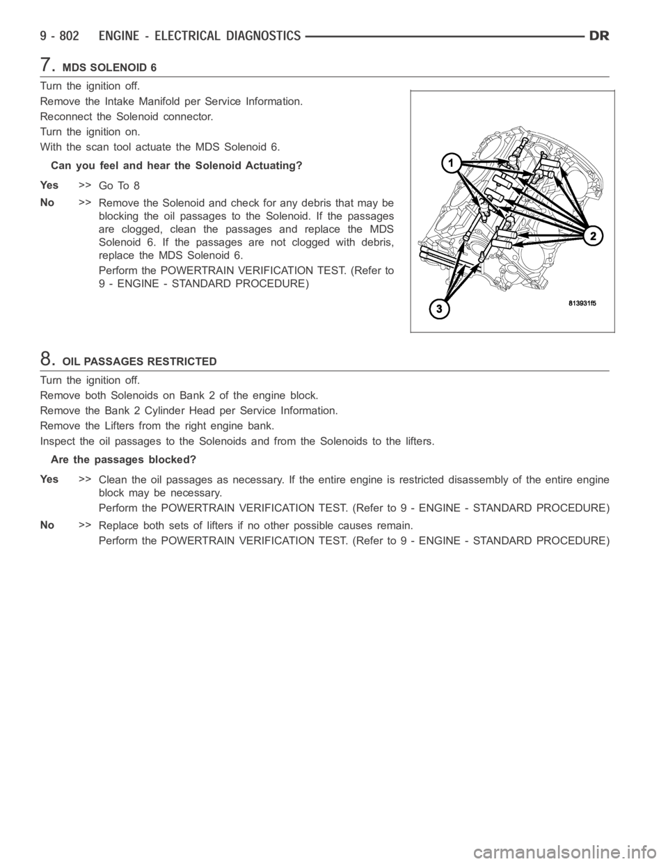
7.MDS SOLENOID 6
Turn the ignition off.
Remove the Intake Manifold per Service Information.
Reconnect the Solenoid connector.
Turn the ignition on.
With the scan tool actuate the MDS Solenoid 6.
Can you feel and hear the Solenoid Actuating?
Ye s>>
Go To 8
No>>
Remove the Solenoid and check for any debris that may be
blocking the oil passages to the Solenoid. If the passages
are clogged, clean the passages and replace the MDS
Solenoid 6. If the passages are not clogged with debris,
replace the MDS Solenoid 6.
Perform the POWERTRAIN VERIFICATION TEST. (Refer to
9 - ENGINE - STANDARD PROCEDURE)
8.OIL PASSAGES RESTRICTED
Turn the ignition off.
Remove both Solenoids on Bank 2 of the engine block.
Remove the Bank 2 Cylinder Head per Service Information.
Remove the Lifters from the right engine bank.
Inspect the oil passages to the Solenoids and from the Solenoids to the lifters.
Are the passages blocked?
Ye s>>
Clean the oil passages as necessary. If the entire engine is restricted disassembly of the entire engine
block may be necessary.
Perform the POWERTRAIN VERIFICATION TEST. (Refer to 9 - ENGINE - STANDARD PROCEDURE)
No>>
Replace both sets of lifters if no other possible causes remain.
Perform the POWERTRAIN VERIFICATION TEST. (Refer to 9 - ENGINE - STANDARD PROCEDURE)
Page 116 of 5267
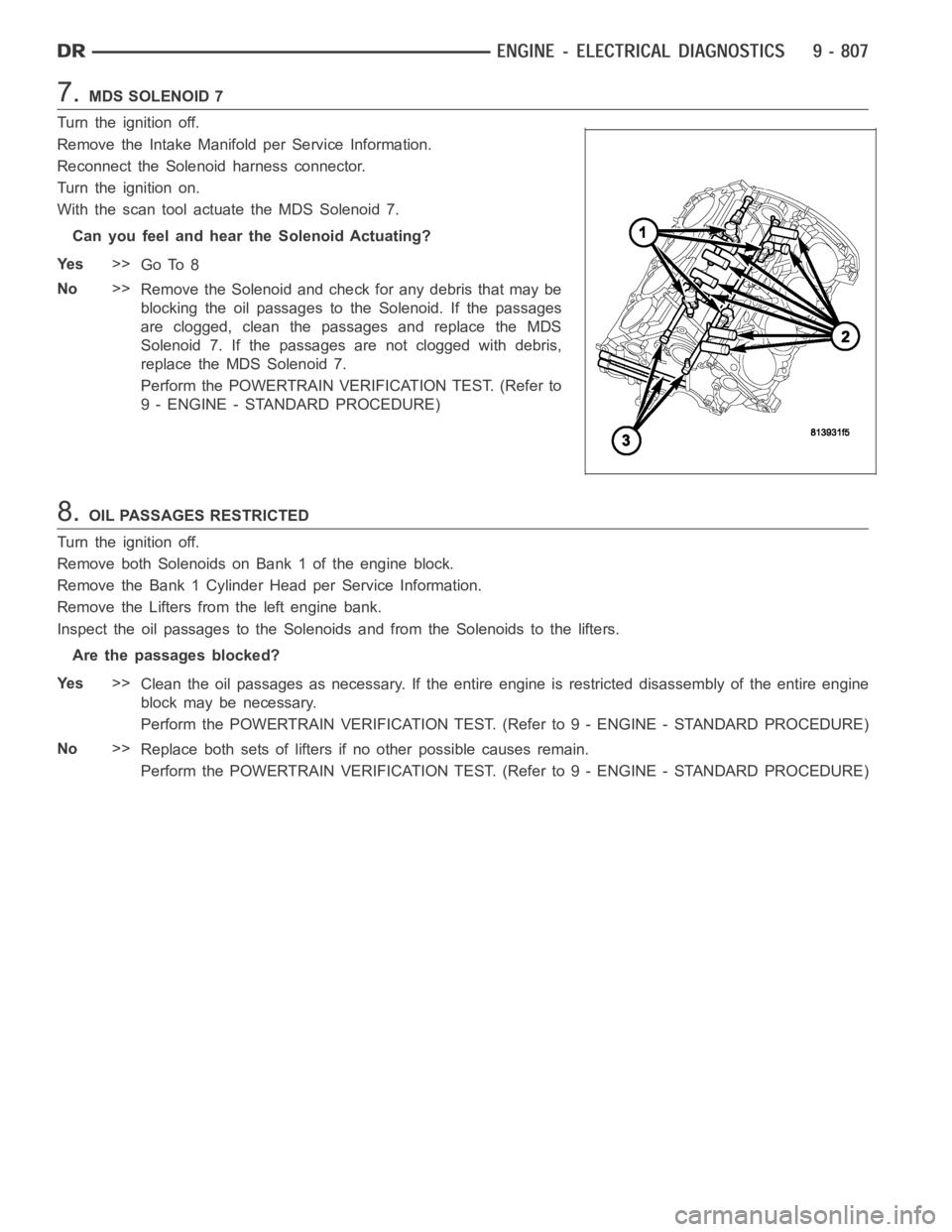
7.MDS SOLENOID 7
Turn the ignition off.
Remove the Intake Manifold per Service Information.
Reconnect the Solenoid harness connector.
Turn the ignition on.
With the scan tool actuate the MDS Solenoid 7.
Can you feel and hear the Solenoid Actuating?
Ye s>>
Go To 8
No>>
Remove the Solenoid and check for any debris that may be
blocking the oil passages to the Solenoid. If the passages
are clogged, clean the passages and replace the MDS
Solenoid 7. If the passages are not clogged with debris,
replace the MDS Solenoid 7.
Perform the POWERTRAIN VERIFICATION TEST. (Refer to
9 - ENGINE - STANDARD PROCEDURE)
8.OIL PASSAGES RESTRICTED
Turn the ignition off.
Remove both Solenoids on Bank 1 of the engine block.
Remove the Bank 1 Cylinder Head per Service Information.
Remove the Lifters from the left engine bank.
Inspect the oil passages to the Solenoids and from the Solenoids to the lifters.
Are the passages blocked?
Ye s>>
Clean the oil passages as necessary. If the entire engine is restricted disassembly of the entire engine
block may be necessary.
Perform the POWERTRAIN VERIFICATION TEST. (Refer to 9 - ENGINE - STANDARD PROCEDURE)
No>>
Replace both sets of lifters if no other possible causes remain.
Perform the POWERTRAIN VERIFICATION TEST. (Refer to 9 - ENGINE - STANDARD PROCEDURE)
Page 165 of 5267
Theory of Operation
This DTC sets when an unexpected high intake manifold air flow condition exists that can lead to increased engine
speed and puts the NGC into a High Air flow Protection limiting mode. The High Air flow Protection feature includes
RPM limits for when a Throttle and/or MAP sensor limp-in fault is present.
When Monitored:
During all drive modes
Set Condition:
If vacuum drops below 1.5
Hg with engine RPM greater than 2000 RPM and closed throttle. One Trip Fault.
Three good trips to turn off the MIL.
Possible Causes
VACUUM LEAK
RESISTANCE IN THE (F856) 5-VOLT SUPPLY CIRCUIT
(F856) 5-VOLT SUPPLY CIRCUIT SHORTED TO GROUND
RESISTANCE IN THE (K1) MAP SIGNAL CIRCUIT
(K1) MAP SIGNAL CIRCUIT SHORTED TO GROUND
RESISTANCE IN THE (F855) 5-VOLT SUPPLY CIRCUIT
(F855) 5-VOLT SUPPLY CIRCUIT SHORTED TO GROUND
RESISTANCE IN THE (K22) TP SENSOR NO.1 SIGNAL CIRCUIT
(K22) TP SENSOR NO.1 SIGNAL CIRCUIT SHORTED TO GROUND
RESISTANCE IN THE (K900) SENSOR GROUND CIRCUIT
MAP SENSOR
THROTTLE POSITION SENSOR
PCM
Always perform the Pre-Diagnostic Troubleshooting procedure before proceeding. (Refer to 9 - ENGINE -
DIAGNOSIS AND TESTING).
Diagnostic Test
1.ACTIVE DTC
NOTE: Diagnose any TP Sensor or MAP Sensor component DTCs before continuing.
NOTE: If the P0501 - No Vehicle Speed Signal is set long with this DTC, refer to the P0501 diagnostics
before continuing.
NOTE: The throttle plate and linkage should be free from binding and carbonbuild up.
NOTE: Make sure the throttle plate is at the idle position.
Ignition on, engine not running.
With a scan tool, read DTCs.
Is the DTC active at this time?
Ye s>>
Go To 2
No>>
Refer to the INTERMITTENT CONDITION Diagnostic Procedure.
Perform the POWERTRAIN VERIFICATION TEST. (Refer to 9 - ENGINE - STANDARD PROCEDURE)
Page 166 of 5267
2.VACUUM LEAK
NOTE: This code is enabled on engines with a plastic intake manifold and is intended to shut down the
engine if a large crack occurs.
NOTE: A large vacuum leak is most likely the cause of this DTC.
Inspect the Intake Manifold for leaks and cracks.
Inspect the Power Brake Booster for any vacuum leaks.
Inspect the PCV system for proper operation and vacuum leaks.
Inspect the throttle plate to see if it is bent and will close entirely, if itis bent it may need to be replaced.
Inspect the MAP Sensor for proper installation.
Verify the engine is free from any mechanical failures.
Were any vacuum leaks found?
Ye s>>
Repair the vacuum leak as necessary.
Perform the POWERTRAIN VERIFICATION TEST. (Refer to 9 - ENGINE - STANDARD PROCEDURE)
No>>
Go To 3
3.MAP SENSOR OPERATION
Start the engine.
With a scan tool, monitor the MAP Sensor voltage.
Snap the throttle.
Does the MAP Sensor voltage vary from below 2.0 volts at idle to above 3.5 volts at wide open throt-
tle?
Ye s>>
Go To 4
No>>
Go To 11
4.TP SENSOR OPERATION
Ignition on, engine not running.
With a scan tool, monitor the TP Sensor voltage while slowly pressing the throttle pedal from closed to wide open
throttle.
Does voltage start at approximately 0.8 of a volt and go above 3.5 volts witha smooth transition?
Ye s>>
Refer to the INTERMITTENT CONDITION Diagnostic Procedure.
Perform the POWERTRAIN VERIFICATION TEST. (Refer to 9 - ENGINE - STANDARD PROCEDURE)
No>>
Go To 5
Page 205 of 5267
P2108-ELECTRONIC THROTTLE CONTROL MODULE PERFORMANCE
For a complete wiring diagramRefer to Section 8W.
When Monitored:
Ignition on.
Set Condition:
Internal PCM failure. Customer may experience an extended cranking condition with limited driving and a
rough idle. One trip fault and the code will set within 5 seconds. ETC light is flashing.
Possible Causes
POWERTRAIN CONTROL MODULE NEEDS TO BE REPROGRAMMED
Always perform the Pre-Diagnostic Troubleshooting procedure before proceeding. (Refer to 9 - ENGINE -
DIAGNOSIS AND TESTING).
Diagnostic Test
1.REPROGRAM THE POWERTRAIN CONTROL MODULE
Check for any related TSBs.
Verify the PCM is at the latest calibration (flash level).
NOTE: Inspect the Intake Manifold components for vacuum leaks, repair as necessary
NOTE: An intermittent loss of power to the PCM without performing an ETC Relearn procedure may cause
this DTC to set.
NOTE: Diagnose any other DTCs that may have set with the P2108.
Flash the Powertrain Control Module per Service Information if any updates are available.
Start the engine.
Allow the engine to reach normal operating temperature.
Operate the accelerator pedal. (do not exceed 3500 rpm)
Test drive the vehicle for 10 miles on a flat road surface.
Does this DTC reset by itself?
Ye s>>
Replace and reprogram the Powertrain Control Module per Service Information.
Perform the POWERTRAIN VERIFICATION TEST. (Refer to 9 - ENGINE - STANDARD PROCEDURE)
No>>
Te s t C o m p l e t e .
Page 271 of 5267

2.VACUUM LEAK
NOTE: This code is enabled on engines with a plastic intake manifold and is intendedtolimitthemaximum
engine speed if a large crack occurs.
NOTE: A large vacuum leak is most likely the cause of this DTC.
Inspect the Intake Manifold and Throttle body for leaks and cracks.
Inspect the Power Brake Booster for any vacuum leaks.
Inspect the PCV system for proper operation or any vacuum leaks.
Inspect the MAP Sensor for proper installation.
Were any vacuum leaks found?
Ye s>>
Repair the vacuum leak as necessary.
Perform the POWERTRAIN VERIFICATION TEST. (Refer to 9 - ENGINE - STANDARD PROCEDURE)
No>>
Go To 3
3.MAP SENSOR OPERATION
Start the engine.
With a scan tool, monitor the MAP Sensor voltage.
Snap the Accelerator pedal.
Does the MAP Sensor voltage vary from below 2.0 volts at idle to above 3.5 volts at Wide Open Throt-
tle?
Ye s>>
Go To 4
No>>
Go To 11
4.TP SENSOR OPERATION
Ignition on, engine not running.
With a scan tool, perform the Throttle Follower Test.
TP Sensor No.1 should start at approximately 0.8 of a volt and increase to 4.2volts.
TP Sensor No.2 should start at approximately 4.2 volts and decrease to 0.8 ofavolt.
Is the voltage transition smooth between the appropriate values?
Ye s>>
Refer to the INTERMITTENT CONDITION Diagnostic Procedure.
Perform the POWERTRAIN VERIFICATION TEST. (Refer to 9 - ENGINE - STANDARD PROCEDURE)
No>>
Go To 5
Page 281 of 5267

2.VACUUM LEAK
NOTE: This code is enabled on engines with a plastic intake manifold and is intendedtolimitthemaximum
engine speed if a large crack occurs.
NOTE: A large vacuum leak is most likely the cause of this DTC.
Inspect the Intake Manifold and Throttle body for leaks and cracks.
Inspect the Power Brake Booster for any vacuum leaks.
Inspect the PCV system for proper operation or any vacuum leaks.
Inspect the MAP Sensor for proper installation.
Were any vacuum leaks found?
Ye s>>
Repair the vacuum leak as necessary.
Perform the POWERTRAIN VERIFICATION TEST. (Refer to 9 - ENGINE - STANDARD PROCEDURE)
No>>
Go To 3
3.MAP SENSOR OPERATION
Start the engine.
With a scan tool, monitor the MAP Sensor voltage.
Snap the Accelerator pedal.
Does the MAP Sensor voltage vary from below 2.0 volts at idle to above 3.5 volts at Wide Open Throt-
tle?
Ye s>>
Go To 4
No>>
Go To 11
4.TP SENSOR OPERATION
Ignition on, engine not running.
With a scan tool, perform the Throttle Follower Test.
TP Sensor No.1 should start at approximately 0.8 of a volt and increase to 4.2volts.
TP Sensor No.2 should start at approximately 4.2 volts and decrease to 0.8 ofavolt.
Is the voltage transition smooth between the appropriate values?
Ye s>>
Refer to the INTERMITTENT CONDITION Diagnostic Procedure.
Perform the POWERTRAIN VERIFICATION TEST. (Refer to 9 - ENGINE - STANDARD PROCEDURE)
No>>
Go To 5
Page 356 of 5267
P3400-MDS RATIONALITY BANK 1
For a complete wiring diagramRefer to Section 8W.
Theory of Operation
When all criteria has been met, power is supplied to each MDS Solenoid when the engine is making a transition
from 8 cylinder mode to 4 cylinder mode. By actuating the solenoid, oil pressure is raised to the pair of lifters that
coincide with each particular solenoid. The oil pressure pushes in the locking pins that allows the lifter to collapse,
decoupling the valves and camshaft.
When Monitored:
Transition from 8 to 4 cylinder mode.
Set Condition:
O2 sensor readings on Bank 1 side indicate a lean condition while in 4 cylinder mode. One trip fault.
Possible Causes
INSUFFICIENT OIL PRESSURE ACTING ON THE LIFTER LOCKING PINS
OIL PASSAGES RESTRICTED
LIFTER
MDS SOLENOID
Always perform the Pre-Diagnostic Troubleshooting procedure before proceeding (Refer to 9 - ENGINE -
DIAGNOSIS AND TESTING).
Diagnostic Test
1.ACTIVE DTC
Ignition on, engine not running.
With a scan tool, read DTCs.
NOTE: Diagnose any Oil Pressure DTCs before continuing.
Is the DTC active at this time?
Ye s>>
Go To 2
No>>
Refer to the INTERMITTENT CONDITION Diagnostic Procedure.
Perform the POWERTRAIN VERIFICATION TEST. (Refer to 9 - ENGINE - STANDARD PROCEDURE)
2.MDS SOLENOID 1
Turn the ignition off.
Remove the Intake Manifold per Service Information.
Turn the ignition on.
With the scan tool actuate the MDS Solenoid 1.
Can you feel and hear the Solenoid Actuating?
Ye s>>
Go To 3
No>>
Remove the Solenoid and check for any debris that may be blocking the oil passages to the Solenoid.
If the passages are clogged, clean the passages and replace the MDS Solenoid1.Ifthepassagesare
not clogged with debris, replace the MDS Solenoid 1.
Perform the POWERTRAIN VERIFICATION TEST. (Refer to 9 - ENGINE - STANDARD PROCEDURE)