maintenance DODGE RAM SRT-10 2006 Service Repair Manual
[x] Cancel search | Manufacturer: DODGE, Model Year: 2006, Model line: RAM SRT-10, Model: DODGE RAM SRT-10 2006Pages: 5267, PDF Size: 68.7 MB
Page 1492 of 5267
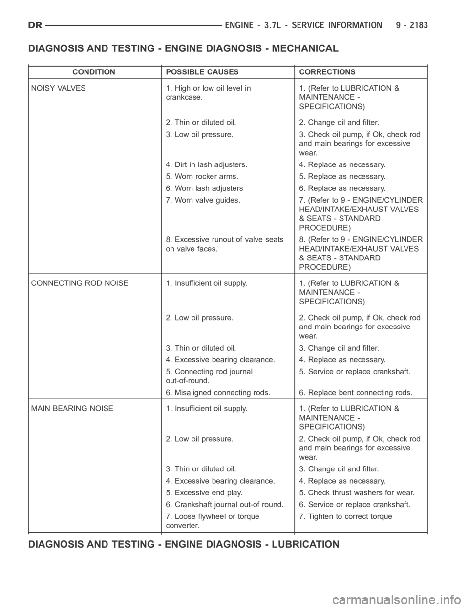
DIAGNOSIS AND TESTING - ENGINE DIAGNOSIS - MECHANICAL
CONDITION POSSIBLE CAUSES CORRECTIONS
NOISY VALVES 1. High or low oil level in
crankcase.1. (Refer to LUBRICATION &
MAINTENANCE -
SPECIFICATIONS)
2. Thin or diluted oil. 2. Change oil and filter.
3. Low oil pressure. 3. Check oil pump, if Ok, check rod
and main bearings for excessive
wear.
4. Dirt in lash adjusters. 4. Replace as necessary.
5. Worn rocker arms. 5. Replace as necessary.
6. Worn lash adjusters 6. Replace as necessary.
7. Worn valve guides. 7. (Refer to 9 - ENGINE/CYLINDER
HEAD/INTAKE/EXHAUST VALVES
& SEATS - STANDARD
PROCEDURE)
8. Excessive runout of valve seats
on valve faces.8. (Refer to 9 - ENGINE/CYLINDER
HEAD/INTAKE/EXHAUST VALVES
& SEATS - STANDARD
PROCEDURE)
CONNECTING ROD NOISE 1. Insufficient oil supply. 1. (Refer to LUBRICATION&
MAINTENANCE -
SPECIFICATIONS)
2. Low oil pressure. 2. Check oil pump, if Ok, check rod
and main bearings for excessive
wear.
3. Thin or diluted oil. 3. Change oil and filter.
4. Excessive bearing clearance. 4. Replace as necessary.
5. Connecting rod journal
out-of-round.5. Service or replace crankshaft.
6. Misaligned connecting rods. 6. Replace bent connecting rods.
MAIN BEARING NOISE 1. Insufficient oil supply. 1. (Refer to LUBRICATION &
MAINTENANCE -
SPECIFICATIONS)
2. Low oil pressure. 2. Check oil pump, if Ok, check rod
and main bearings for excessive
wear.
3. Thin or diluted oil. 3. Change oil and filter.
4. Excessive bearing clearance. 4. Replace as necessary.
5. Excessive end play. 5. Check thrust washers for wear.
6. Crankshaft journal out-of round. 6. Service or replace crankshaft.
7. Loose flywheel or torque
converter.7. Tighten to correct torque
DIAGNOSIS AND TESTING - ENGINE DIAGNOSIS - LUBRICATION
Page 1598 of 5267
OIL
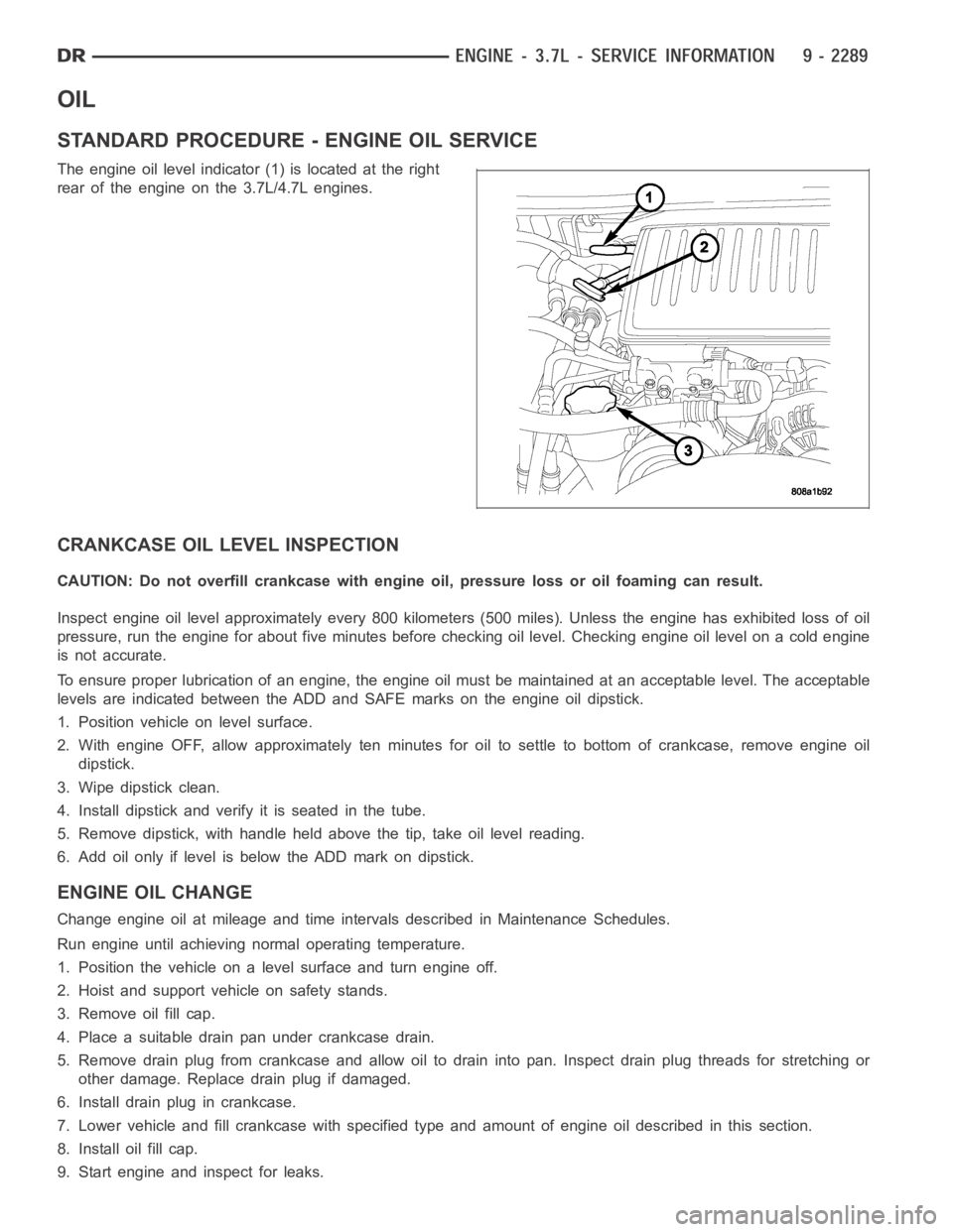
STANDARD PROCEDURE - ENGINE OIL SERVICE
The engine oil level indicator (1) is located at the right
rear of the engine on the 3.7L/4.7L engines.
CRANKCASE OIL LEVEL INSPECTION
CAUTION: Do not overfill crankcase with engine oil, pressure loss or oil foaming can result.
Inspect engine oil level approximately every 800 kilometers (500 miles).Unless the engine has exhibited loss of oil
pressure, run the engine for about five minutes before checking oil level.Checking engine oil level on a cold engine
is not accurate.
To ensure proper lubrication of an engine, the engine oil must be maintained at an acceptable level. The acceptable
levels are indicated between the ADD and SAFE marks on the engine oil dipstick.
1. Position vehicle on level surface.
2. With engine OFF, allow approximately ten minutes for oil to settle to bottom of crankcase, remove engine oil
dipstick.
3. Wipe dipstick clean.
4. Install dipstick and verify it is seated in the tube.
5. Remove dipstick, with handle held above the tip, take oil level reading.
6. Add oil only if level is below the ADD mark on dipstick.
ENGINE OIL CHANGE
Change engine oil at mileage and time intervals described in Maintenance Schedules.
Run engine until achieving normal operating temperature.
1. Position the vehicle on a level surface and turn engine off.
2. Hoist and support vehicle on safety stands.
3. Remove oil fill cap.
4. Place a suitable drain pan under crankcase drain.
5. Remove drain plug from crankcase and allow oil to drain into pan. Inspectdrain plug threads for stretching or
other damage. Replace drain plug if damaged.
6. Install drain plug in crankcase.
7. Lower vehicle and fill crankcase with specified type and amount of engine oil described in this section.
8. Install oil fill cap.
9. Start engine and inspect for leaks.
Page 1627 of 5267
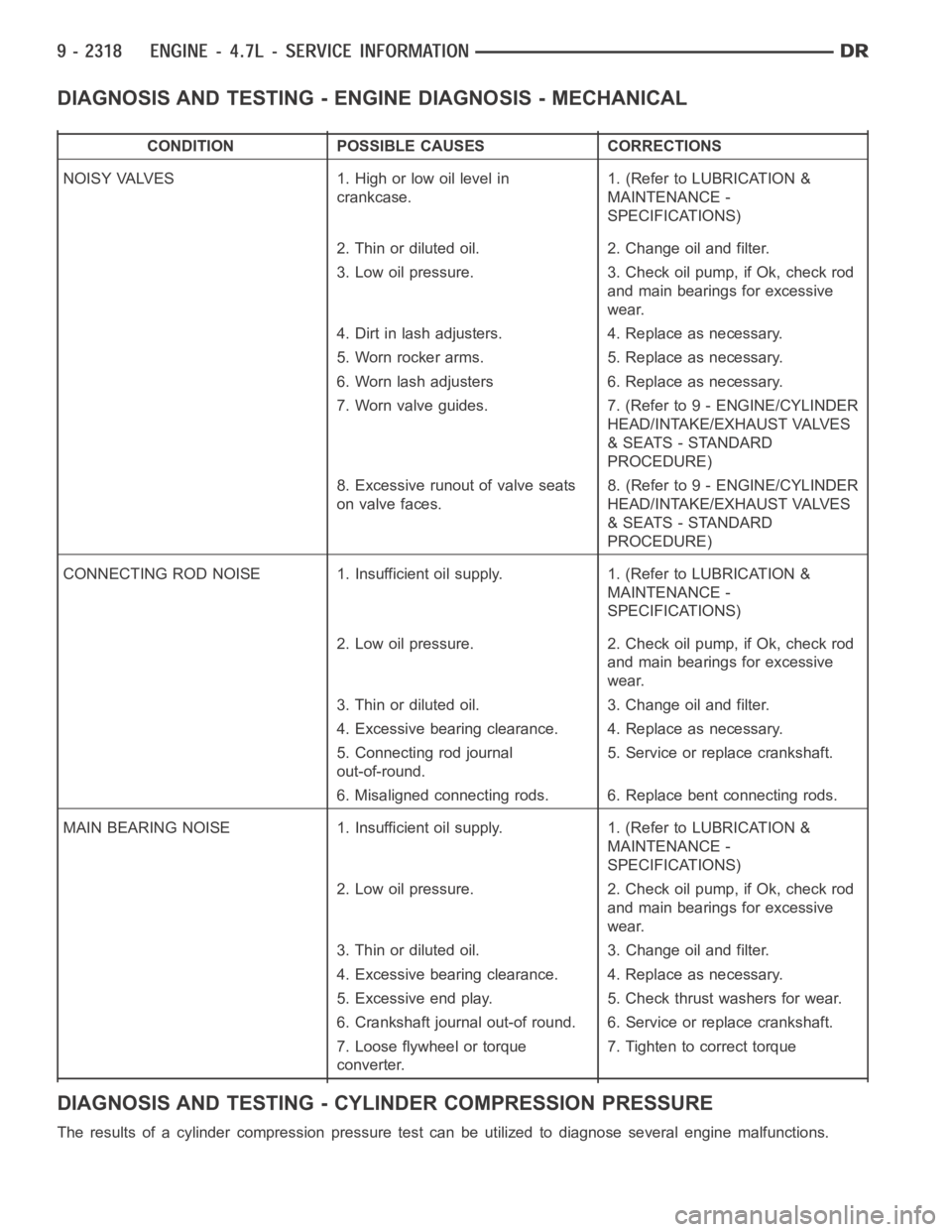
DIAGNOSIS AND TESTING - ENGINE DIAGNOSIS - MECHANICAL
CONDITION POSSIBLE CAUSES CORRECTIONS
NOISY VALVES 1. High or low oil level in
crankcase.1. (Refer to LUBRICATION &
MAINTENANCE -
SPECIFICATIONS)
2. Thin or diluted oil. 2. Change oil and filter.
3. Low oil pressure. 3. Check oil pump, if Ok, check rod
and main bearings for excessive
wear.
4. Dirt in lash adjusters. 4. Replace as necessary.
5. Worn rocker arms. 5. Replace as necessary.
6. Worn lash adjusters 6. Replace as necessary.
7. Worn valve guides. 7. (Refer to 9 - ENGINE/CYLINDER
HEAD/INTAKE/EXHAUST VALVES
& SEATS - STANDARD
PROCEDURE)
8. Excessive runout of valve seats
on valve faces.8. (Refer to 9 - ENGINE/CYLINDER
HEAD/INTAKE/EXHAUST VALVES
& SEATS - STANDARD
PROCEDURE)
CONNECTING ROD NOISE 1. Insufficient oil supply. 1. (Refer to LUBRICATION&
MAINTENANCE -
SPECIFICATIONS)
2. Low oil pressure. 2. Check oil pump, if Ok, check rod
and main bearings for excessive
wear.
3. Thin or diluted oil. 3. Change oil and filter.
4. Excessive bearing clearance. 4. Replace as necessary.
5. Connecting rod journal
out-of-round.5. Service or replace crankshaft.
6. Misaligned connecting rods. 6. Replace bent connecting rods.
MAIN BEARING NOISE 1. Insufficient oil supply. 1. (Refer to LUBRICATION &
MAINTENANCE -
SPECIFICATIONS)
2. Low oil pressure. 2. Check oil pump, if Ok, check rod
and main bearings for excessive
wear.
3. Thin or diluted oil. 3. Change oil and filter.
4. Excessive bearing clearance. 4. Replace as necessary.
5. Excessive end play. 5. Check thrust washers for wear.
6. Crankshaft journal out-of round. 6. Service or replace crankshaft.
7. Loose flywheel or torque
converter.7. Tighten to correct torque
DIAGNOSIS AND TESTING - CYLINDER COMPRESSION PRESSURE
The results of a cylinder compressionpressure test can be utilized to diagnose several engine malfunctions.
Page 1723 of 5267
OIL
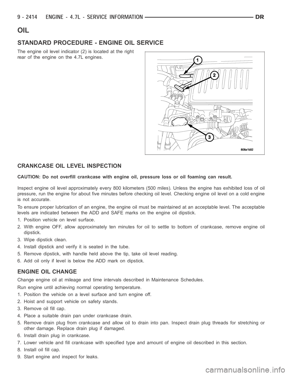
STANDARD PROCEDURE - ENGINE OIL SERVICE
The engine oil level indicator (2) is located at the right
rear of the engine on the 4.7L engines.
CRANKCASE OIL LEVEL INSPECTION
CAUTION: Do not overfill crankcase with engine oil, pressure loss or oil foaming can result.
Inspect engine oil level approximately every 800 kilometers (500 miles).Unless the engine has exhibited loss of oil
pressure, run the engine for about five minutes before checking oil level.Checking engine oil level on a cold engine
is not accurate.
To ensure proper lubrication of an engine, the engine oil must be maintained at an acceptable level. The acceptable
levels are indicated between the ADD and SAFE marks on the engine oil dipstick.
1. Position vehicle on level surface.
2. With engine OFF, allow approximately ten minutes for oil to settle to bottom of crankcase, remove engine oil
dipstick.
3. Wipe dipstick clean.
4. Install dipstick and verify it is seated in the tube.
5. Remove dipstick, with handle held above the tip, take oil level reading.
6. Add oil only if level is below the ADD mark on dipstick.
ENGINE OIL CHANGE
Change engine oil at mileage and time intervals described in Maintenance Schedules.
Run engine until achieving normal operating temperature.
1. Position the vehicle on a level surface and turn engine off.
2. Hoist and support vehicle on safety stands.
3. Remove oil fill cap.
4. Place a suitable drain pan under crankcase drain.
5. Remove drain plug from crankcase and allow oil to drain into pan. Inspectdrain plug threads for stretching or
other damage. Replace drain plug if damaged.
6. Install drain plug in crankcase.
7. Lower vehicle and fill crankcase with specified type and amount of engine oil described in this section.
8. Install oil fill cap.
9. Start engine and inspect for leaks.
Page 1760 of 5267
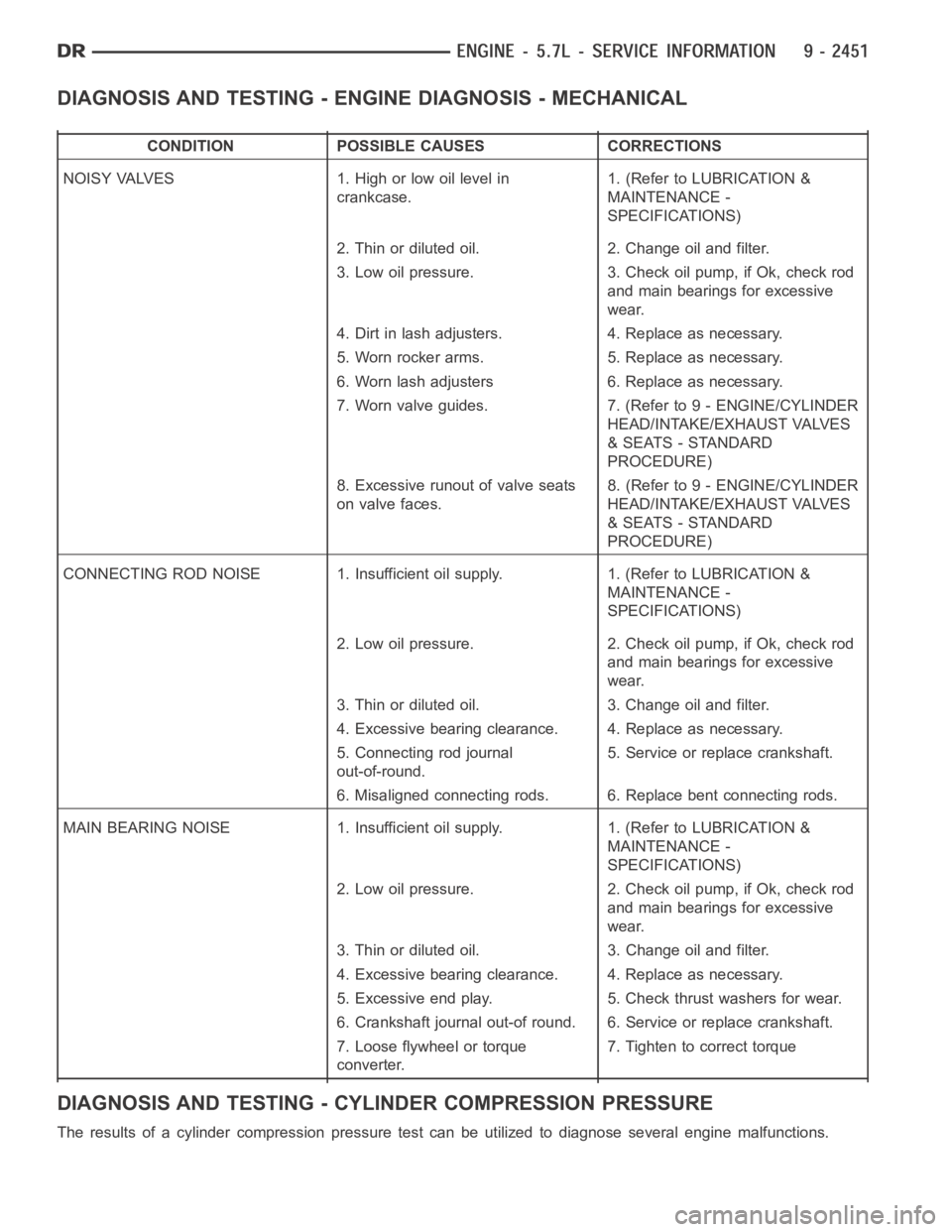
DIAGNOSIS AND TESTING - ENGINE DIAGNOSIS - MECHANICAL
CONDITION POSSIBLE CAUSES CORRECTIONS
NOISY VALVES 1. High or low oil level in
crankcase.1. (Refer to LUBRICATION &
MAINTENANCE -
SPECIFICATIONS)
2. Thin or diluted oil. 2. Change oil and filter.
3. Low oil pressure. 3. Check oil pump, if Ok, check rod
and main bearings for excessive
wear.
4. Dirt in lash adjusters. 4. Replace as necessary.
5. Worn rocker arms. 5. Replace as necessary.
6. Worn lash adjusters 6. Replace as necessary.
7. Worn valve guides. 7. (Refer to 9 - ENGINE/CYLINDER
HEAD/INTAKE/EXHAUST VALVES
& SEATS - STANDARD
PROCEDURE)
8. Excessive runout of valve seats
on valve faces.8. (Refer to 9 - ENGINE/CYLINDER
HEAD/INTAKE/EXHAUST VALVES
& SEATS - STANDARD
PROCEDURE)
CONNECTING ROD NOISE 1. Insufficient oil supply. 1. (Refer to LUBRICATION&
MAINTENANCE -
SPECIFICATIONS)
2. Low oil pressure. 2. Check oil pump, if Ok, check rod
and main bearings for excessive
wear.
3. Thin or diluted oil. 3. Change oil and filter.
4. Excessive bearing clearance. 4. Replace as necessary.
5. Connecting rod journal
out-of-round.5. Service or replace crankshaft.
6. Misaligned connecting rods. 6. Replace bent connecting rods.
MAIN BEARING NOISE 1. Insufficient oil supply. 1. (Refer to LUBRICATION &
MAINTENANCE -
SPECIFICATIONS)
2. Low oil pressure. 2. Check oil pump, if Ok, check rod
and main bearings for excessive
wear.
3. Thin or diluted oil. 3. Change oil and filter.
4. Excessive bearing clearance. 4. Replace as necessary.
5. Excessive end play. 5. Check thrust washers for wear.
6. Crankshaft journal out-of round. 6. Service or replace crankshaft.
7. Loose flywheel or torque
converter.7. Tighten to correct torque
DIAGNOSIS AND TESTING - CYLINDER COMPRESSION PRESSURE
The results of a cylinder compressionpressure test can be utilized to diagnose several engine malfunctions.
Page 1765 of 5267
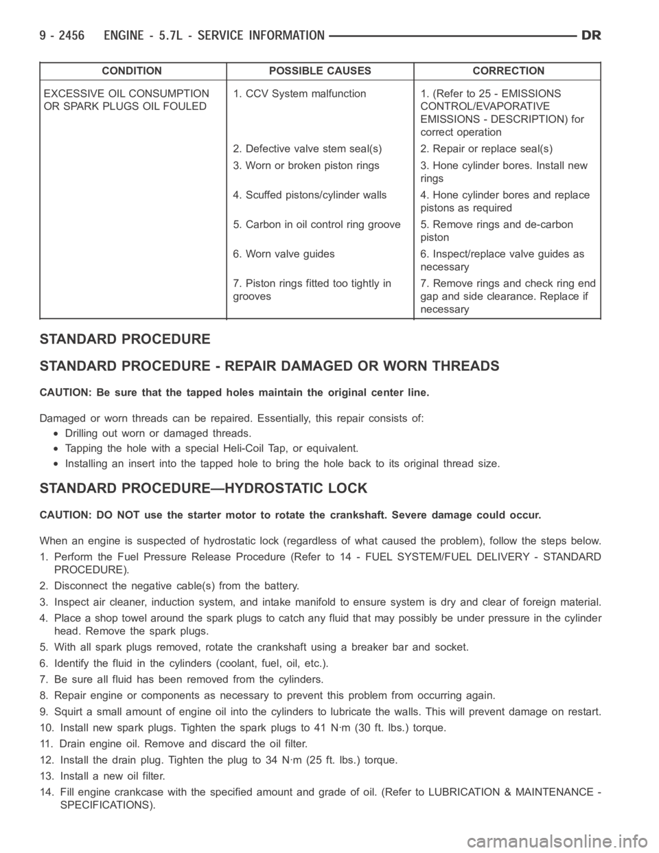
CONDITION POSSIBLE CAUSES CORRECTION
EXCESSIVE OIL CONSUMPTION
OR SPARK PLUGS OIL FOULED1. CCV System malfunction 1. (Refer to 25 - EMISSIONS
CONTROL/EVAPORATIVE
EMISSIONS - DESCRIPTION) for
correct operation
2. Defective valve stem seal(s) 2. Repair or replace seal(s)
3. Worn or broken piston rings 3. Hone cylinder bores. Install new
rings
4. Scuffed pistons/cylinder walls 4. Hone cylinder bores and replace
pistons as required
5. Carbon in oil control ring groove 5. Remove rings and de-carbon
piston
6. Worn valve guides 6. Inspect/replace valve guides as
necessary
7. Piston rings fitted too tightly in
grooves7. Remove rings and check ring end
gap and side clearance. Replace if
necessary
STANDARD PROCEDURE
STANDARD PROCEDURE - REPAIR DAMAGED OR WORN THREADS
CAUTION: Be sure that the tapped holes maintain the original center line.
Damaged or worn threads can be repaired. Essentially, this repair consistsof:
Drilling out worn or damaged threads.
Tapping the hole with a special Heli-Coil Tap, or equivalent.
Installing an insert into the tapped hole to bring the hole back to its original thread size.
STANDARD PROCEDURE—HYDROSTATIC LOCK
CAUTION: DO NOT use the starter motor to rotate the crankshaft. Severe damage could occur.
When an engine is suspected of hydrostatic lock (regardless of what causedthe problem), follow the steps below.
1. Perform the Fuel Pressure Release Procedure (Refer to 14 - FUEL SYSTEM/FUEL DELIVERY - STANDARD
PROCEDURE).
2. Disconnect the negative cable(s) from the battery.
3. Inspect air cleaner, induction system, and intake manifold to ensure system is dry and clear of foreign material.
4. Place a shop towel around the spark plugs to catch any fluid that may possibly be under pressure in the cylinder
head. Remove the spark plugs.
5. With all spark plugs removed, rotate the crankshaft using a breaker bar and socket.
6. Identify the fluid in the cylinders (coolant, fuel, oil, etc.).
7. Be sure all fluid has been removed from the cylinders.
8. Repair engine or components as necessary to prevent this problem from occurring again.
9. Squirt a small amount of engine oil into the cylinders to lubricate the walls. This will prevent damage on restart.
10. Install new spark plugs. Tighten the spark plugs to 41 Nꞏm (30 ft. lbs.) torque.
11. Drain engine oil. Remove and discard the oil filter.
12. Install the drain plug. Tighten the plug to 34 Nꞏm (25 ft. lbs.) torque.
13. Install a new oil filter.
14. Fill engine crankcase with the specified amount and grade of oil. (Refer to LUBRICATION & MAINTENANCE -
SPECIFICATIONS).
Page 1776 of 5267

26. Install the fan shroud (3).
27. Install the fan (Refer to 7 - COOLING/ENGINE/
RADIATOR FAN - INSTALLATION).
28. Connect the radiator upper hose.
29. Install the washer bottle.
30. Connect the transmission cooler lines.
31. Install the air cleaner resonator and duct work..
32. Add engine oil to crankcase (Refer to LUBRICA-
TION & MAINTENANCE/FLUID TYPES - SPECI-
FICATIONS).
33. Fill cooling system (Refer to 7 - COOLING -
STANDARD PROCEDURE).
34. Connect battery negative cable.
35. Start engine and inspect for leaks.
36. Road test vehicle.
SPECIFICATIONS
5.7L ENGINE
GENERAL DESCRIPTION
DESCRIPTION SPECIFICATION
Engine Type 90° V-8 OHV
Displacement 5.7 Liters
345 ( Cubic Inches)
Bore 99.5 mm (3.91 in.)
Stroke 90.9 mm (3.58 in.)
Compression Ratio 9.6:1
Firing Order 1-8-4-3-6-5-7-2
Lubrication Pressure Feed - Full Flow
Filtration
Cooling System Liquid Cooled - Forced
Circulation
Cylinder Block Cast Iron
Cylinder Head Aluminum
Crankshaft Nodular Iron
Camshaft Hollow Assembled Camshaft
Pistons Aluminum Alloy
Connecting Rods Powdered Metal
CYLINDER BLOCK
Page 1877 of 5267
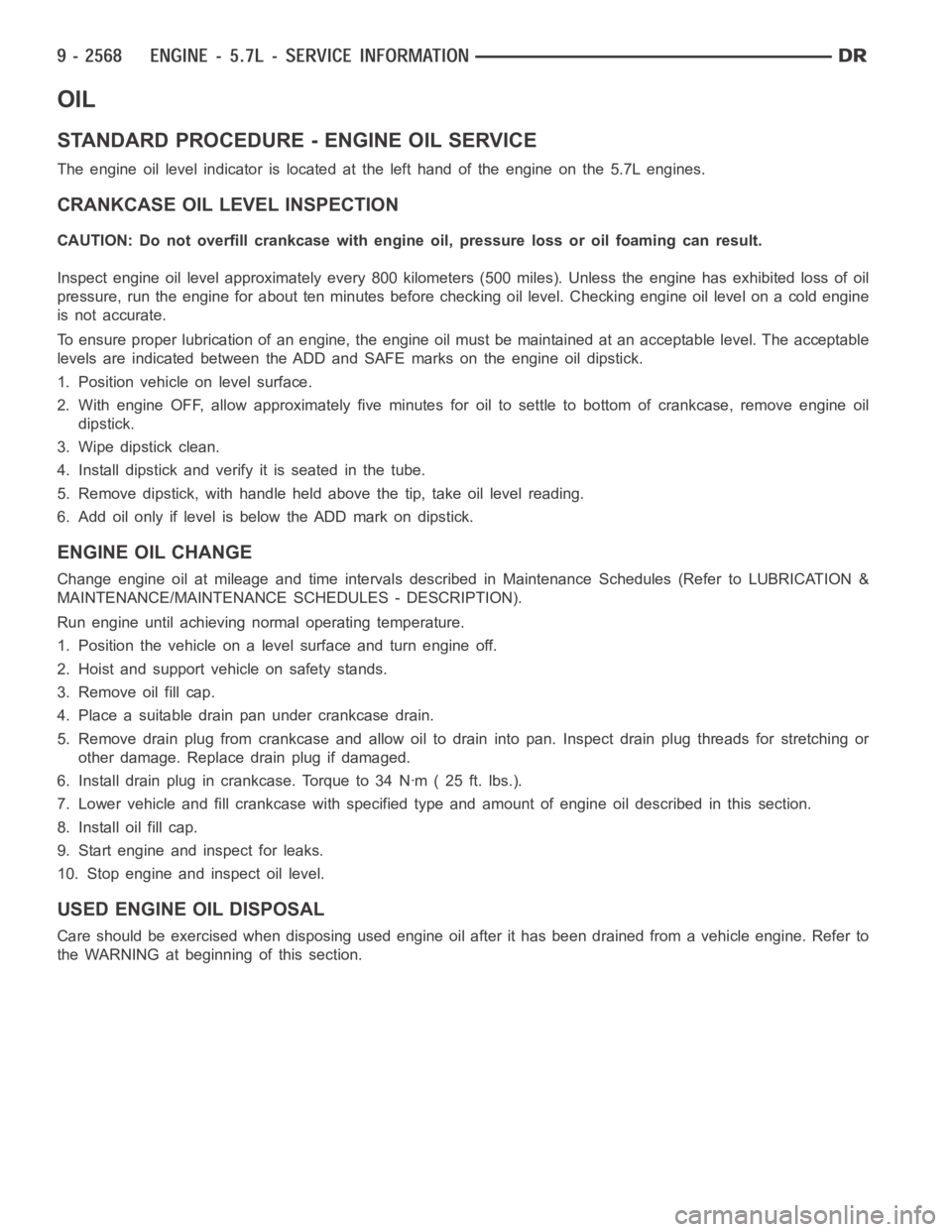
OIL
STANDARD PROCEDURE - ENGINE OIL SERVICE
The engine oil level indicator is located at the left hand of the engine on the 5.7L engines.
CRANKCASE OIL LEVEL INSPECTION
CAUTION: Do not overfill crankcase with engine oil, pressure loss or oil foaming can result.
Inspect engine oil level approximately every 800 kilometers (500 miles).Unless the engine has exhibited loss of oil
pressure, run the engine for about ten minutes before checking oil level. Checking engine oil level on a cold engine
is not accurate.
To ensure proper lubrication of an engine, the engine oil must be maintained at an acceptable level. The acceptable
levels are indicated between the ADD and SAFE marks on the engine oil dipstick.
1. Position vehicle on level surface.
2. With engine OFF, allow approximately five minutes for oil to settle to bottom of crankcase, remove engine oil
dipstick.
3. Wipe dipstick clean.
4. Install dipstick and verify it is seated in the tube.
5. Remove dipstick, with handle held above the tip, take oil level reading.
6. Add oil only if level is below the ADD mark on dipstick.
ENGINE OIL CHANGE
Change engine oil at mileage and time intervals described in Maintenance Schedules (Refer to LUBRICATION &
MAINTENANCE/MAINTENANCESCHEDULES - DESCRIPTION).
Run engine until achieving normal operating temperature.
1. Position the vehicle on a level surface and turn engine off.
2. Hoist and support vehicle on safety stands.
3. Remove oil fill cap.
4. Place a suitable drain pan under crankcase drain.
5. Remove drain plug from crankcase and allow oil to drain into pan. Inspectdrain plug threads for stretching or
other damage. Replace drain plug if damaged.
6. Install drain plug in crankcase. Torque to 34 Nꞏm ( 25 ft. lbs.).
7. Lower vehicle and fill crankcase with specified type and amount of engine oil described in this section.
8. Install oil fill cap.
9. Start engine and inspect for leaks.
10. Stop engine and inspect oil level.
USED ENGINE OIL DISPOSAL
Care should be exercised when disposing used engine oil after it has been drained from a vehicle engine. Refer to
the WARNING at beginning of this section.
Page 1906 of 5267
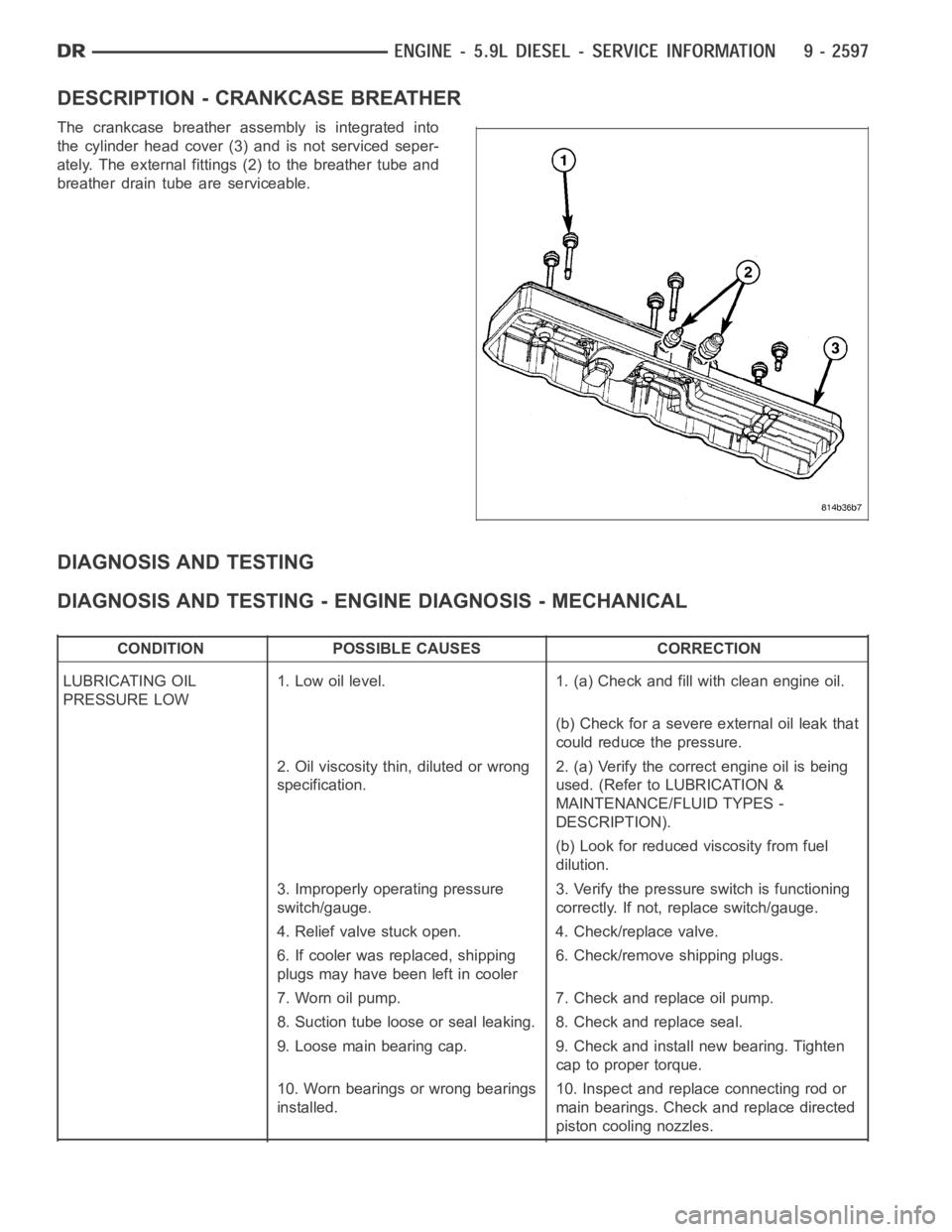
DESCRIPTION - CRANKCASE BREATHER
The crankcase breather assembly is integrated into
the cylinder head cover (3) and is not serviced seper-
ately. The external fittings (2) to the breather tube and
breather drain tube are serviceable.
DIAGNOSIS AND TESTING
DIAGNOSIS AND TESTING - ENGINE DIAGNOSIS - MECHANICAL
CONDITION POSSIBLE CAUSES CORRECTION
LUBRICATING OIL
PRESSURE LOW1. Low oil level. 1. (a) Check and fill with clean engine oil.
(b) Check for a severe external oil leak that
could reduce the pressure.
2. Oil viscosity thin, diluted or wrong
specification.2. (a) Verify the correct engine oil is being
used. (Refer to LUBRICATION &
MAINTENANCE/FLUID TYPES -
DESCRIPTION).
(b) Look for reduced viscosity from fuel
dilution.
3. Improperly operating pressure
switch/gauge.3. Verify the pressure switch is functioning
correctly. If not, replace switch/gauge.
4. Relief valve stuck open. 4. Check/replace valve.
6. If cooler was replaced, shipping
plugs may have been left in cooler6. Check/remove shipping plugs.
7. Worn oil pump. 7. Check and replace oil pump.
8. Suction tube loose or seal leaking. 8. Check and replace seal.
9. Loose main bearing cap. 9. Check and install new bearing. Tighten
cap to proper torque.
10. Worn bearings or wrong bearings
installed.10. Inspect and replace connecting rod or
main bearings. Check and replace directed
piston cooling nozzles.
Page 1907 of 5267
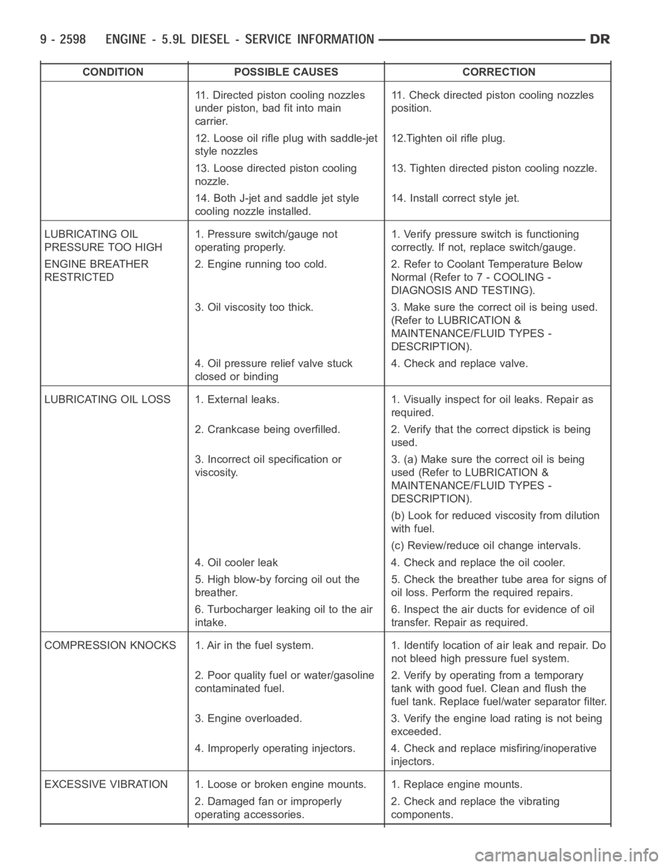
CONDITION POSSIBLE CAUSES CORRECTION
11. Directed piston cooling nozzles
under piston, bad fit into main
carrier.11. Check directed piston cooling nozzles
position.
12. Loose oil rifle plug with saddle-jet
style nozzles12.Tighten oil rifle plug.
13. Loose directed piston cooling
nozzle.13. Tighten directed piston cooling nozzle.
14. Both J-jet and saddle jet style
cooling nozzle installed.14. Install correct style jet.
LUBRICATING OIL
PRESSURE TOO HIGH1. Pressure switch/gauge not
operating properly.1. Verify pressure switch is functioning
correctly. If not, replace switch/gauge.
ENGINE BREATHER
RESTRICTED2. Engine running too cold. 2. Refer to Coolant Temperature Below
Normal (Refer to 7 - COOLING -
DIAGNOSIS AND TESTING).
3. Oil viscosity too thick. 3. Make sure the correct oil is being used.
(Refer to LUBRICATION &
MAINTENANCE/FLUID TYPES -
DESCRIPTION).
4. Oil pressure relief valve stuck
closed or binding4. Check and replace valve.
LUBRICATING OIL LOSS 1. External leaks. 1. Visually inspect for oil leaks.Repair as
required.
2. Crankcase being overfilled. 2. Verify that the correct dipstick is being
used.
3. Incorrect oil specification or
viscosity.3. (a) Make sure the correct oil is being
used (Refer to LUBRICATION &
MAINTENANCE/FLUID TYPES -
DESCRIPTION).
(b) Look for reduced viscosity from dilution
with fuel.
(c) Review/reduce oil change intervals.
4. Oil cooler leak 4. Check and replace the oil cooler.
5. High blow-by forcing oil out the
breather.5. Check the breather tube area for signs of
oil loss. Perform the required repairs.
6. Turbocharger leaking oil to the air
intake.6. Inspect the air ducts for evidence of oil
transfer. Repair as required.
COMPRESSION KNOCKS 1. Air in the fuel system. 1. Identify location of air leak and repair. Do
not bleed high pressure fuel system.
2. Poor quality fuel or water/gasoline
contaminated fuel.2. Verify by operating from a temporary
tank with good fuel. Clean and flush the
fuel tank. Replace fuel/water separator filter.
3. Engine overloaded. 3. Verify the engine load rating is not being
exceeded.
4. Improperly operating injectors. 4. Check and replace misfiring/inoperative
injectors.
EXCESSIVE VIBRATION 1. Loose or broken engine mounts. 1. Replace engine mounts.
2. Damaged fan or improperly
operating accessories.2. Check and replace the vibrating
components.