DODGE SPRINTER 2005 1.G Owners Manual
Manufacturer: DODGE, Model Year: 2005, Model line: SPRINTER, Model: DODGE SPRINTER 2005 1.GPages: 288, PDF Size: 27.89 MB
Page 201 of 288

WHAT TO DO IN EMERGENCIES 201
6
Spare Wheel Beneath the End of the FrameRetaining screws for the spare wheel structural member
(1)Hook (2)
1. Open the cargo doors and remove the retaining screws (1) with the lug wrench from the vehicle
tool kit.
2. Lift the spare wheel structural member, unhinge the hooks (2), and lower the spare wheel structural
member. Remove the spare wheel. Spare Wheel in Cargo Area (Optional)
1. Open the rear cargo doors.
Page 202 of 288
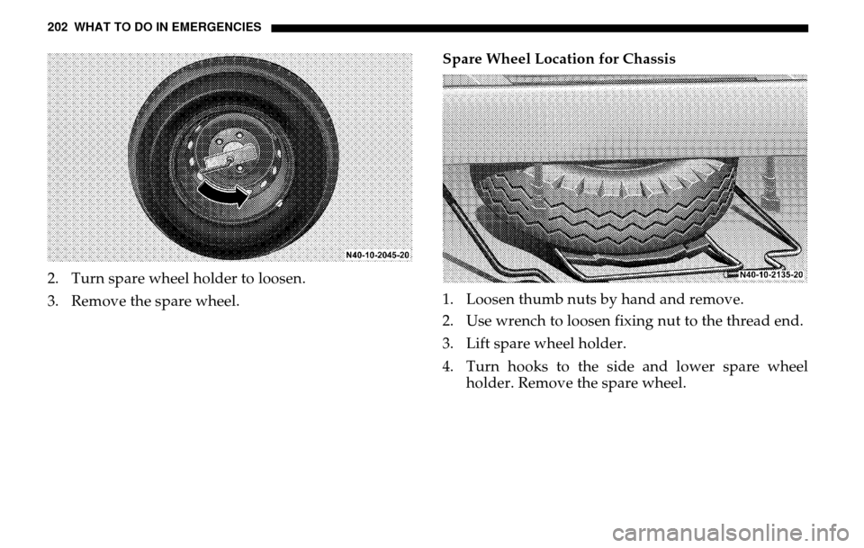
202 WHAT TO DO IN EMERGENCIES2. Turn spare wheel holder to loosen.
3. Remove the spare wheel. Spare Wheel Location for Chassis
1. Loosen thumb nuts by hand and remove.
2. Use wrench to loosen fixing nut to the thread end.
3. Lift spare wheel holder.
4. Turn hooks to the side and lower spare wheel
holder. Remove the spare wheel.
Page 203 of 288

WHAT TO DO IN EMERGENCIES 203
6
JACK Using the Jack
The jack is located together with the vehicle tool kit
under the hatch in the front passenger footwell, refer to
"Vehicle Tool Kit".
1. Loosen the wheel bolts before raising the vehicle.
2. Close the release valve on the jack.
3. Assemble the pump leve r provided and insert it
into the socket on the jack.
4. Secure the lever by turning it clockwise in the socket.
Position the jack under the appropriate jack point and
raise the vehicle by pumping the lever.
WARNING!
To avoid the risk of serious or fatal injuries or vehicle
damage, please bear the fo llowing points in mind:
The jack is intended only for raising the vehicle briefly, for instance, when changing a wheel. If it is
not designed to enable work to be carried out
underneath the vehicle.
Do not crawl under the jacked-up vehicle. For work
under the vehicle, stands must be used.
The jack must be placed on a firm, flat surface only.
Do not change wheels on uphill or downhill gradients under any circumstances.
Make sure that no persons are present in the vehicle when jacking up the vehicle.
Do not start the engine while the vehicle is raised.
Make sure that the distance between the underside of the tires and the ground does not exceed 1.2 in (30
mm). Otherwise the vehicle may tip over.
Page 204 of 288
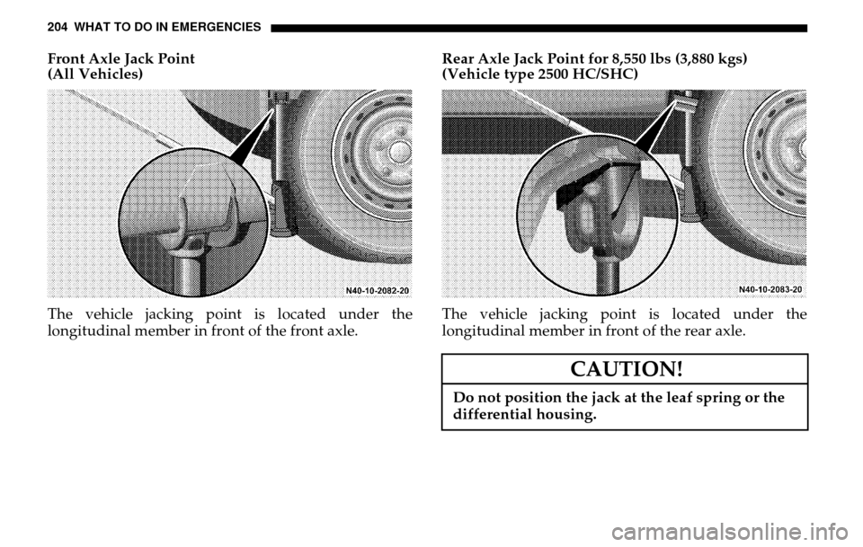
204 WHAT TO DO IN EMERGENCIESFront Axle Jack Point
(All Vehicles)
The vehicle jacking poin t is located under the
longitudinal member in front of the front axle. Rear Axle Jack Point for 8,550 lbs (3,880 kgs)
(Vehicle type 2500 HC/SHC)
The vehicle jacking point is located under the
longitudinal member in front of the rear axle.
CAUTION!
Do not position the jack at the leaf spring or the
differential housing.
Page 205 of 288
WHAT TO DO IN EMERGENCIES 205
6
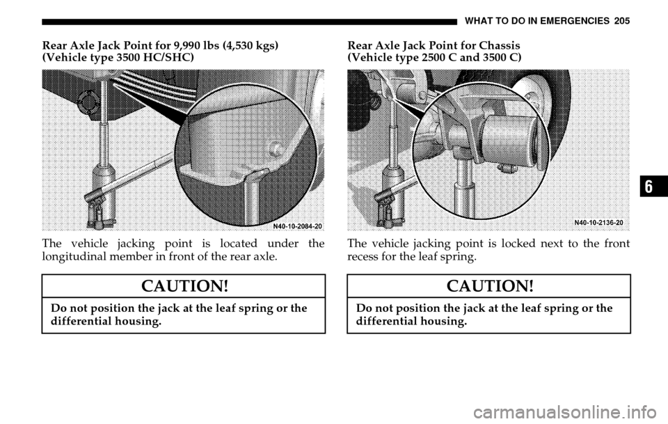
Rear Axle Jack Point for 9,990 lbs (4,530 kgs)
(Vehicle type 3500 HC/SHC)
The vehicle jacking poin t is located under the
longitudinal member in front of the rear axle. Rear Axle Jack Point for Chassis
(Vehicle type 2500 C and 3500 C)
The vehicle jacking point is locked next to the front
recess for the leaf spring.
CAUTION!
Do not position the jack at the leaf spring or the
differential housing.
CAUTION!
Do not position the jack at the leaf spring or the
differential housing.
Page 206 of 288
206 WHAT TO DO IN EMERGENCIESREMOVING A WHEEL1. Loosen the wheel bolts.
2. Jack up the vehicle until the wheel is clear of the ground.
3. Unscrew the wheel bolts and remove the wheel
(keep the wheel bolts clean).
NOTE: If the vehicle moves forwards or backwards
while it is being jacked-up, lower it again and
reposition the jack. When the vehicle is jacked-up, the
jack must stand vertically (plumb-line).
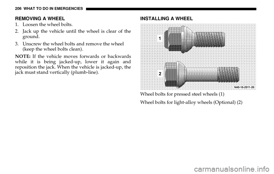
INSTALLING A WHEELWheel bolts for pressed steel wheels (1)
Wheel bolts for light-alloy wheels (Optional) (2)
Page 207 of 288
WHAT TO DO IN EMERGENCIES 207
6
NOTE: The optional light alloy wheels are supplied
with 5 short wheel lug bolts enclosed for the steel spare
wheel in the vehicle tool kit.
Before fitting the spare wheel, clean rust and dirt off the contact surfaces of the wheel and the wheel hub,
and from the wheel bolts.
Note the specified wheel and tire size, tire load capacity and speed code.
Do not change the tire’s direction of rotation.
Do not damage, grease or oil wheel bolts or their threads.
WARNING!
Different wheel bolts are required for pressed
steel and light-alloy wheels.
Incorrect wheel lug bolts for the wheels could
work loose, thereby causing you to lose control of
the vehicle. This could cause an accident resulting
in severe personal injuries and and property
damage.
WARNING!
Incorrect mounting bolts or improperly tightened
mounting bolts can cause the wheel to come off.
To avoid the risk of serious or fatal injuries or ve-
hicle damage, please bear the following points in
mind:• Always replace wheel bolts that are damaged or
rusted.• Never apply oil or grease to wheel bolts• If a wheel hub thread is damaged, you must not
drive the vehicle. Consult a qualified specialist
workshop.
Page 208 of 288
208 WHAT TO DO IN EMERGENCIESCentering wheels with wheel bolts
If dual assemblies are used, before placement the inner wheel should be inspected to ensure that all
ball bearing rings are in proper position.
Install the wheel and snug the wheel bolts.
Slightly tighten wheel bolts.
Slowly open jack release va lve to lower vehicle until
tire is resting on ground.
Tighten the wheel bolts in a crosswise pattern to the specified torque with a torque wrench.
Tightening torque for 8,550 lbs (3,880 kgs)
(vehicle type 2500 C/HC/SHC):
Steel wheel – 177 lbf.ft ±7 lbf.ft (240 N.m ±10 N.m)
Light alloy wheel – 138 lbf.ft ±14 lbf.ft
(190 N.m ±20 N.m) Tightening torque for 9,990 lbs (4,530 kgs)
(vehicle type 3500 C/HC/SHC):
Steel wheel – 138lbf.ft ±14lbf.ft (190N.m ±20N.m)
Remove jack and stow it in the vehicle tool kit.
Check the tire pressure.
Re-tighten the wheel bolts to the specified torque with a torque wrench after a distance of 30 miles
(about 50 km).
WARNING!
Do not tighten the wheel bolts and wheel nuts
completely while the vehicle is still jacked up.
The vehicle could tip.
WARNING!
After changing a wheel, you must, for safety reasons, have the specified tightening torque checked. The
wheels could otherwise work loose.
check the tire pressure and correct it if necessary.
retighten the wheel bolts and wheel nuts to the specified tightening torque once the vehicle has
been driven for 30 miles (50 km).
have a reversed direction of tire rotation corrected as soon as possible at a qualified specialist
workshop. The vehicle handling characteristics
could otherwise be affected.
Page 209 of 288
WHAT TO DO IN EMERGENCIES 209
6
JUMP STARTINGIf the battery is dead, the engine can be started with
jumper cables from another vehicle’s battery.
WARNING!
A battery will produce hydrogen gas, which is
flammable and very explosive. Avoid open flames
and the formation of sparks in the vicinity of the
batteries. Refrain from smoking or cell phone use.
Avoid improper connection of jumper cables.
Observe safety precautions when handling
batteries.
Exercise care near moving engine components and
electrical cables.
Failure to follow these directions will cause
damage to the electronic components and can lead
to a battery explosion and severe injury or death.
WARNING!
Battery fluid contains sulfuric acid. Do not allow
this fluid to come in contact with eyes, skin or
clothing. In case it does, immediately flush affect-
ed area with water, and seek medical help.
The battery housing could be damaged. Never
lean over batteries while connecting or jump-
starting. You might get injured.
Read all instructions before proceeding.
Page 210 of 288
210 WHAT TO DO IN EMERGENCIES A dead battery can freeze at a temperature of 14
°F
(–10
°C). Never try to start the engine if the battery
is frozen. Thaw the battery out first.
Only use a battery of the same rated voltage and of approximately the same capacity for jump-starting.
The two vehicles must not touch.
Switch off all electrical accessories.
Run the vehicle with the booster battery at idle.
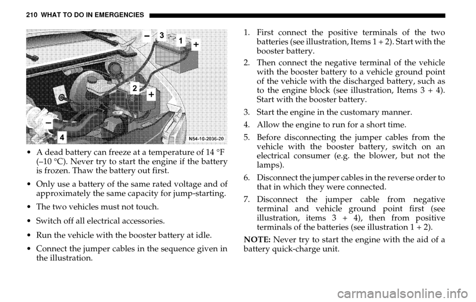
Connect the jumper cables in the sequence given in the illustration. 1. First connect the positive terminals of the two
batteries (see illustration, Items 1 + 2). Start with the
booster battery.
2. Then connect the negative terminal of the vehicle with the booster battery to a vehicle ground point
of the vehicle with the discharged battery, such as
to the engine block (see illustration, Items 3 + 4).
Start with the booster battery.
3. Start the engine in the customary manner.
4. Allow the engine to run for a short time.
5. Before disconnecting the jumper cables from the vehicle with the booster battery, switch on an
electrical consumer (e.g. the blower, but not the
lamps).
6. Disconnect the jumper cables in the reverse order to that in which they were connected.
7. Disconnect the jumper cable from negative terminal and vehicle ground point first (see
illustration, items 3 + 4), then from positive
terminals of the batteries (see illustration 1 + 2).
NOTE: Never try to start the engine with the aid of a
battery quick-charge unit.