DODGE SPRINTER 2006 1.G Owners Manual
Manufacturer: DODGE, Model Year: 2006, Model line: SPRINTER, Model: DODGE SPRINTER 2006 1.GPages: 330, PDF Size: 10.82 MB
Page 151 of 330

STARTING AND OPERATING 151
5
NOTE: Coasting the vehicle, or driving with gear
selector lever in "N" can result in transmission damage
that is not covered by the Sprinter Warranty.
wThe transmission automatically upshifts through
5th gear. Position "D" provides optimum driving
characteristics under all normal operating
conditions.
Gear Selection for Special Circumstances
The transmission gear ranges for special circumstances can
be selected by pushing the gear selector lever to the right or
the left with the gear selector lever in position "D".
The gear range currently selected is indicated in the
instrument cluster display.
Briefly press gear selector lever in the ç direction:
The transmission downshifts, one gear range at a time,
in the order "4", "3", "2", "1".
Press and hold gear selector lever in the ç direction:
The transmission will shift to a gear range which
favorably accelerates or decelerates the vehicle. This
way downshiftings can be caused.Briefly press gear selector lever in the æ direction:
The transmission will shift from the current gear range
to the next higher gear range. If the transmission is
already in gear range "D", an additional upshift of one
gear is not possible.
Press and hold gear selector lever in the æ direction:
The transmission will shift from the current gear range
directly to gear range "D".
NOTE: With transmission in gear range "D", "4" or "3",
upshifting from 1st to 2nd to 3rd gear is delayed
depending on vehicle speed and engine temperature.
This allows the catalytic converter to heat up more
quickly to operating temperatures.
During the brief warm-up period this delayed upshift
and increased engine noise might be perceived as a
malfunction. However, neither the engine nor
WARNING!
On slippery road surfaces, never downshift in order
to slow the vehicle down. This could result in drive
wheel slip and reduced vehicle control. Your vehi-
cle’s ABS will not prevent this type of loss of control.
Page 152 of 330

152 STARTING AND OPERATING
transmission are negatively affected by this mode of
operation.
The delayed upshift is effective with vehicle speeds
below 31 mph (50 km / h) at partial throttle and engine
temperatures below 95 °F (+35 °C).
To avoid overrevving the engine when the gear
selector lever is moved to a lower gear, the
transmission will not shift to a lower gear if the
engine’s revolutions per minute limit would be
exceeded. In this case there will be no downshift, even
when the vehicle speed reaches the engine’s rpm limit
of that gear, for example by applying the service
brakes.
To prevent the engine from laboring at low rpm when
driving uphill grades or with your vehicle heavily
loaded, the automatic transmission will downshift
when necessary to maintain engine rpm within the best
torque range.Gear
qUpshift through 4th gear only. Suitable for
performance driving.
pUpshift through 3rd gear only. Suitable for
moderately steep hills. Since the transmission
does not shift higher than 3rd gear, this gear
selection will allow use of the engine’s braking
power downhill.
oUpshift through 2nd gear only. For driving in
mountainous regions or under extreme
operating conditions. This gear selection will
allow use of the engine’s braking power when
descending steep grades.
nUse this position, which makes maximum use of
the engine’s braking effect, while descending
very steep or lengthy downgrades and only at
speeds below 25 mph (38 km / h).
Page 153 of 330

STARTING AND OPERATING 153
5
TRANSMISSION SELECTOR LEVER, MANUALLY
UNLOCKING
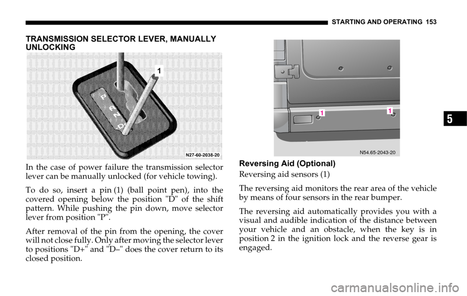
In the case of power failure the transmission selector
lever can be manually unlocked (for vehicle towing).
To do so, insert a pin (1) (ball point pen), into the
covered opening below the position "D" of the shift
pattern. While pushing the pin down, move selector
lever from position "P".
After removal of the pin from the opening, the cover
will not close fully. Only after moving the selector lever
to positions "D+" and "D–" does the cover return to its
closed position.Reversing Aid (Optional)
Reversing aid sensors (1)
The reversing aid monitors the rear area of the vehicle
by means of four sensors in the rear bumper.
The reversing aid automatically provides you with a
visual and audible indication of the distance between
your vehicle and an obstacle, when the key is in
position 2 in the ignition lock and the reverse gear is
engaged.
11
N54.65-2043-20
Page 154 of 330

154 STARTING AND OPERATING
The system is operational if after reverse gear is
engaged:
an acknowledgement tone sounds
the multi-function indicator shows the distance to
an obstacle that has been detected.
WARNING!
The reversing aid is feature designed to provide as-
sistance and may not detect all obstacles. The sys-
tem is not a replacement for your own diligence.
The reversing aid does not detect people and/or
objects within a range of approximately 12 in (30
cm). There is a possibility that certain objects
which could come into contact with the vehicle at
the rear will not be detected by the system’s
sensors. This could cause an accident resulting in
severe personal injuries, death and property
damage.
For this reason, you should make sure before
manuevring that no people or animals are in the
maneuvring range of the vehicle.
Pay particular attention to people and/or objects
above or below sensors when parking, such as
small children, toddlers, flower pots or trailer
towbars.
You are always responsible for safety at all times
and must continue to pay attention to your
immediate surroundings when manoeuvring. A
second person should assist you in manouevring if
necessary.
Page 155 of 330

STARTING AND OPERATING 155
5
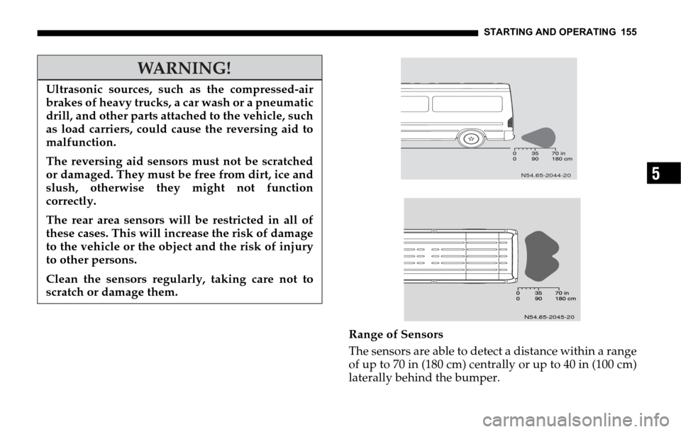
Range of Sensors
The sensors are able to detect a distance within a range
of up to 70 in (180 cm) centrally or up to 40 in (100 cm)
laterally behind the bumper.
WARNING!
Ultrasonic sources, such as the compressed-air
brakes of heavy trucks, a car wash or a pneumatic
drill, and other parts attached to the vehicle, such
as load carriers, could cause the reversing aid to
malfunction.
The reversing aid sensors must not be scratched
or damaged. They must be free from dirt, ice and
slush, otherwise they might not function
correctly.
The rear area sensors will be restricted in all of
these cases. This will increase the risk of damage
to the vehicle or the object and the risk of injury
to other persons.
Clean the sensors regularly, taking care not to
scratch or damage them.
N54.65-2044-20
N54.65-2045-20
Page 156 of 330

156 STARTING AND OPERATING
For all sensors, the minimum distance between sensor
and obstacle is 12 in (30 cm).
In the event of a malfunction, a continuous warning
signal sounds for approximately three seconds when
the vehicle is reversing
NOTE: Distance display
"in" in USA only
"cm" in Canada onlyLOADING THE VEHICLE
WARNING!
Do not overload the tires by exceeding the specified
vehicle capacity weight (as indicated by the label on
the base of the driver’s seat). Overloading the tires
can overheat them, possibly causing a blowout,
which could cause an accident and personal injury.
In addition, braking and stopping distances can be
significantly longer if the vehicle is overloaded.
WARNING!
Always close the sliding and rear doors when
driving.
Otherwise exhaust fumes could enter the vehicle
interior and poison you.
Page 157 of 330

STARTING AND OPERATING 157
5
The handling characteristics of a vehicle when laden
are dependent on the type of load and the distribution
of the load within the vehicle.
Carrying heavy or bulky loads may alter the vehicle’s
handling characteristic.
Loading Guidelines
Please note and comply with the following information
when loading and transporting goods.
Do not allow the load, including passengers, to
exceed the permitted gross vehicle weight or the
permitted axle loads for the vehicle. Bear in mind
that the unladen weight could be increased by
installing items of optional equipment and
accessories.
Distribute the load uniformly. Excessive loads on
individual points of the load surface could cause
damage to the floor covering.
Transport heavy loads between the axles near the
rear axle as low as possible in the vehicle.
Secure any kind of load with sufficient wear and
tear-resistant load restraints. See tie-down rings.WARNING!
Unsecured or poorly secured loads, and seats that
have been removed, could move around the vehi-
cle interior uncontrollably in the event of sudden
braking, a rapid change in direction or an acci-
dent. This increases the risk of injury to occu-
pants in these situations.
Secure and position a load as described in the
following loading guidelines.
Piling up heavy objects or placing them on upper
shelves or loading them otherwise high up in the
vehicle will significantly raise the center of
gravity of the vehicle. Placing excessive loads on
individual points of the load surface or behind
the rear axle will also adversely affect the
handling characteristics of your vehicle and may
lead to loss of control over the vehicle.
Road safety and tire durability are adversely
affected if the permissible axle loads or gross
vehicle weight are exceeded due to the vehicle’s
load. Braking and stopping distances can be
significantly longer.
Page 158 of 330

158 STARTING AND OPERATING
Protect sharp edges with padding.
Check the tire pressures after loading the vehicle.
For passenger vans:
Do not stack loads higher than the upper edge of the
backrests.
Always place the load against the backrests of the
seat benches.
Whenever possible, transport loads behind seats
that are not occupied.
Distribute the load in such a way that the
permissible axle loads are not exceeded when the
vehicle is equipped with the maximum number of
seats. Loading the luggage compartment up to the
maximum payload would cause the permissible
rear axle load to be exceeded.BRAKES
Service Brake
WARNING!
When the engine is not running, the brake and
steering systems are without power assistance.
Under these circumstances, a much greater effort
is necessary to stop or steer the vehicle.
After driving in heavy rain for some time without
applying the brakes or through water deep
enough to wet brake components, the first
braking action may be somewhat reduced and
increased pedal pressure may be necessary. Be
sure to maintain a safe distance from vehicles in
front.
Resting your foot on the brake pedal will cause
excessive and premature wear of the brake pads.
It can also result in the brakes overheating,
thereby significantly reducing their effectiveness.
It may not be possible to stop the vehicle in
sufficient time to avoid an accident.
Page 159 of 330

STARTING AND OPERATING 159
5
NOTE: On long and steep downhill slopes, reduce the
load on the brakes by shifting down a gear to utilize the
braking effect of the engine.
To prevent corrosion on the brake pads, after driving
on very wet roads, especially if road salts have been
used, apply brakes before parking the vehicle. The heat
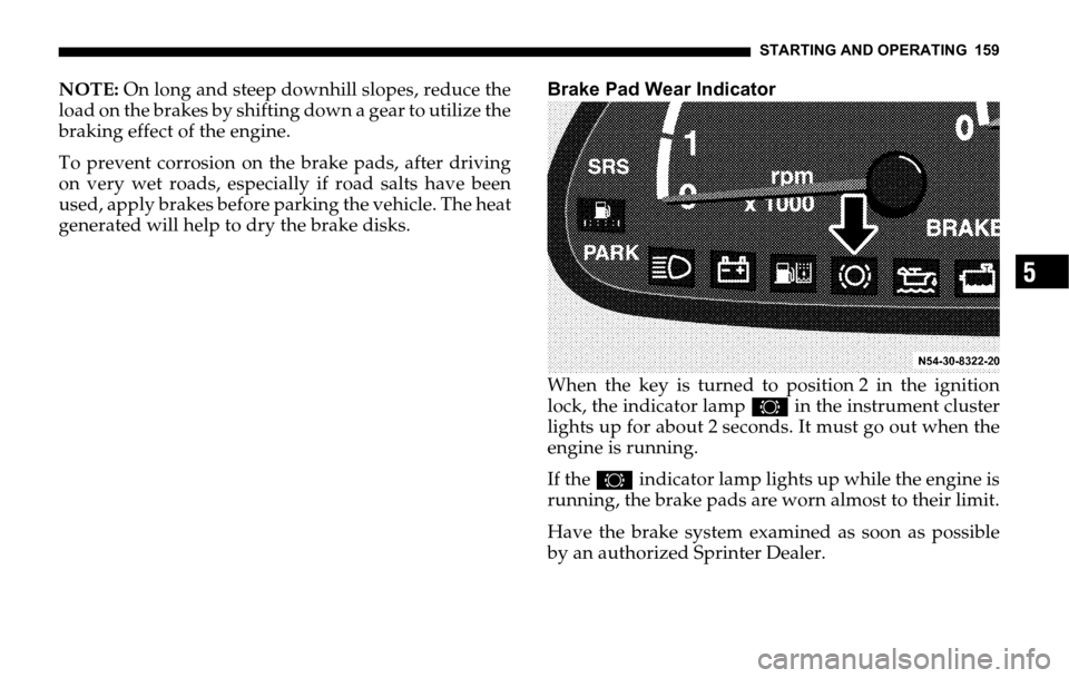
generated will help to dry the brake disks.Brake Pad Wear Indicator
When the key is turned to position 2 in the ignition
lock, the indicator lamp2 in the instrument cluster
lights up for about 2 seconds. It must go out when the
engine is running.
If the 2indicator lamp lights up while the engine is
running, the brake pads are worn almost to their limit.
Have the brake system examined as soon as possible
by an authorized Sprinter Dealer.
Page 160 of 330

160 STARTING AND OPERATING
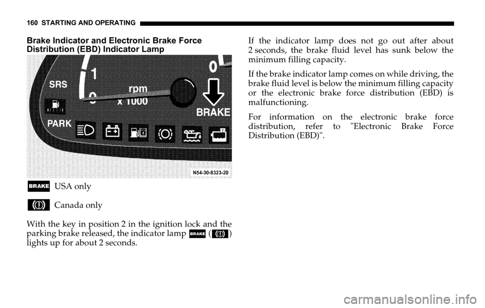
Brake Indicator and Electronic Brake Force
Distribution (EBD) Indicator Lamp
;USA only
3Canada only
With the key in position 2 in the ignition lock and the
parking brake released, the indicator lamp; (3)
lights up for about 2 seconds.If the indicator lamp does not go out after about
2 seconds, the brake fluid level has sunk below the
minimum filling capacity.
If the brake indicator lamp comes on while driving, the
brake fluid level is below the minimum filling capacity
or the electronic brake force distribution (EBD) is
malfunctioning.
For information on the electronic brake force
distribution, refer to "Electronic Brake Force
Distribution (EBD)".