engine DODGE SPRINTER 2007 2.G Owners Manual
[x] Cancel search | Manufacturer: DODGE, Model Year: 2007, Model line: SPRINTER, Model: DODGE SPRINTER 2007 2.GPages: 393, PDF Size: 7.61 MB
Page 340 of 393
339 Practical hints
Battery
5
\1Recharge the removed battery. Ob-
serve the notes in the operating in-
structions for your battery charger.
\1Reinstall the battery in the reverse or-
der.\1Switch off all electrical consumers.
\1Connect the positive terminal and se-
cure the cover.
\1Connect the negative terminal.Recharging the battery!
CAUTION
Only charge the installed battery using
a battery charger tested and approved
by the manufacturer. These devices al-
low you to charge the battery while it is
installed. The vehicle’s electronics sys-
tem may otherwise be damaged.
Warning
G
Only charge the battery in well-ventilated ar-
eas. As the battery is being charged, gases
can escape and generate minor explosions,
which can injure you and others and may
cause damage to the paintwork or permit
acid corrosion on the vehicle.
During the charge procedure, there is a risk
of acid burns due to gases escaping from
the battery. Do not, therefore, lean over the
battery while it is being recharged.iIt is also possible to charge the starter
battery using the jump-starting connec-
tion point in the engine compartment
(\2page 340).
Reconnecting the battery!
CAUTION
Never swap the terminal clamps. Other-
wise, the vehicle’s electronics system
may be damaged. After reconnecting
the battery, you must reset the electric
sliding door* (\2page 57).
Page 341 of 393
340 Practical hintsJump-starting
5
\3 Jump-startingIf the starter battery in the battery recess
in the driver’s footwell is discharged, the
engine can be jump-started from another
vehicle using jump leads.
For this purpose, the vehicle is equipped
with a jump-starting connection point.
Please note:
\4Jump-starting must only be performed
when the engine and catalytic convert-
er are cold.\4Do not start the engine if the battery
has frozen. Let the battery thaw out
first.
\4Only use a battery of the same rated
voltage and of approximately the same
capacity for jump-starting.
\4Only use jumper cables of adequate
cross-section with insulated battery
terminal clamps.
\1Make sure that the two vehicles do not
touch.
\1Apply the handbrake or move the se-
lector lever to positionP.
\1Switch off all electrical consumers.
\1Switch on the battery isolating switch*
if necessary (\2page 197).\1Remove the key from the ignition lock.
\1Open the hood (\2page 185).
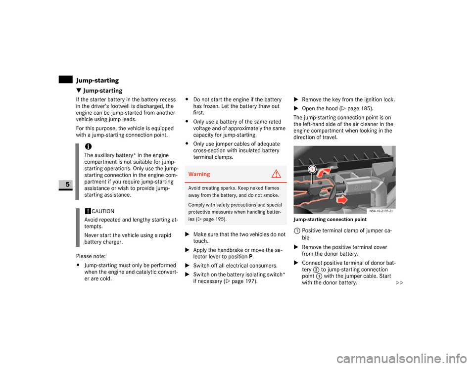
The jump-starting connection point is on
the left-hand side of the air cleaner in the
engine compartment when looking in the
direction of travel.
Jump-starting connection point1Positive terminal clamp of jumper ca-
ble
\1Remove the positive terminal cover
from the donor battery.
\1Connect positive terminal of donor bat-
tery 2 to jump-starting connection
point 1 with the jumper cable. Start
with the donor battery.
iThe auxiliary battery* in the engine
compartment is not suitable for jump-
starting operations. Only use the jump-
starting connection in the engine com-
partment if you require jump-starting
assistance or wish to provide jump-
starting assistance.!
CAUTION
Avoid repeated and lengthy starting at-
tempts.
Never start the vehicle using a rapid
battery charger.
Warning
G
Avoid creating sparks. Keep naked flames
away from the battery, and do not smoke.
Comply with safety precautions and special
protective measures when handling batter-
ies (\2page 195).
\2\2
Page 342 of 393
341 Practical hints
Jump-starting
5
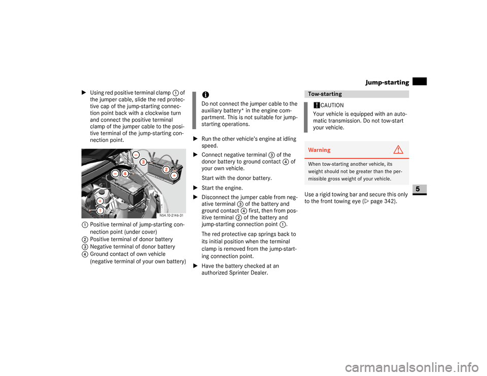
\1Using red positive terminal clamp1 of
the jumper cable, slide the red protec-
tive cap of the jump-starting connec-
tion point back with a clockwise turn
and connect the positive terminal
clamp of the jumper cable to the posi-
tive terminal of the jump-starting con-
nection point.
1Positive terminal of jump-starting con-
nection point (under cover)
2Positive terminal of donor battery
3Negative terminal of donor battery
4Ground contact of own vehicle
(negative terminal of your own battery)\1Run the other vehicle’s engine at idling
speed.
\1Connect negative terminal3 of the
donor battery to ground contact4 of
your own vehicle.
Start with the donor battery.
\1Start the engine.
\1Disconnect the jumper cable from neg-
ative terminal3 of the battery and
ground contact 4 first, then from pos-
itive terminal 2 of the battery and
jump-starting connection point 1.
The red protective cap springs back to
its initial position when the terminal
clamp is removed from the jump-start-
ing connection point.
\1Have the battery checked at an
authorized Sprinter Dealer.Use a rigid towing bar and secure this only
to the front towing eye (\2page 342).
iDo not connect the jumper cable to the
auxiliary battery* in the engine com-
partment. This is not suitable for jump-
starting operations.
Tow-starting!
CAUTION
Your vehicle is equipped with an auto-
matic transmission. Do not tow-start
your vehicle.
Warning
G
When tow-starting another vehicle, its
weight should not be greater than the per-
missible gross weight of your vehicle.
Page 343 of 393
342 Practical hintsTowing
5
\3 TowingComply with legal regulations when tow-
ing.
Having the vehicle carried away on a trans-
porter or trailer is preferable to towing it
away. We recommend the use of a rigid
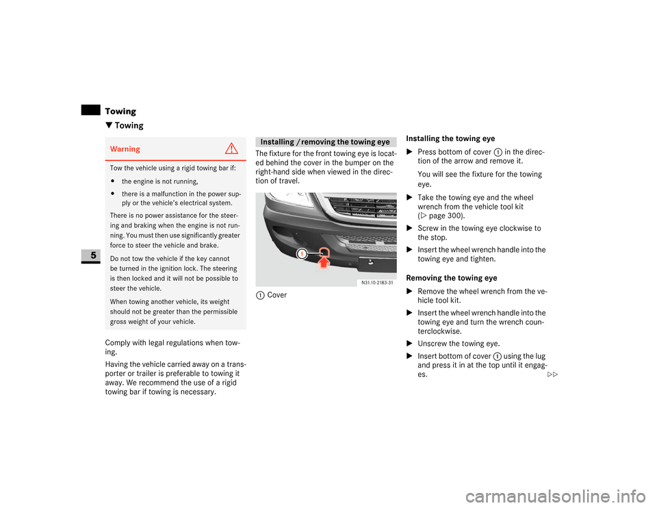
towing bar if towing is necessary.The fixture for the front towing eye is locat-
ed behind the cover in the bumper on the
right-hand side when viewed in the direc-
tion of travel.
1CoverInstalling the towing eye
\1Press bottom of cover1 in the direc-
tion of the arrow and remove it.
You will see the fixture for the towing
eye.
\1Take the towing eye and the wheel
wrench from the vehicle tool kit
(\2page 300).
\1Screw in the towing eye clockwise to
the stop.
\1Insert the wheel wrench handle into the
towing eye and tighten.
Removing the towing eye
\1Remove the wheel wrench from the ve-
hicle tool kit.
\1Insert the wheel wrench handle into the
towing eye and turn the wrench coun-
terclockwise.
\1Unscrew the towing eye.
\1Insert bottom of cover 1 using the lug
and press it in at the top until it engag-
es.Warning
G
Tow the vehicle using a rigid towing bar if:
\4the engine is not running,
\4there is a malfunction in the power sup-
ply or the vehicle’s electrical system.
There is no power assistance for the steer-
ing and braking when the engine is not run-
ning. You must then use significantly greater
force to steer the vehicle and brake.
Do not tow the vehicle if the key cannot
be turned in the ignition lock. The steering
is then locked and it will not be possible to
steer the vehicle.
When towing another vehicle, its weight
should not be greater than the permissible
gross weight of your vehicle.
Installing / removing the towing eye
\2\2
Page 348 of 393
347 Practical hintsFuses
5
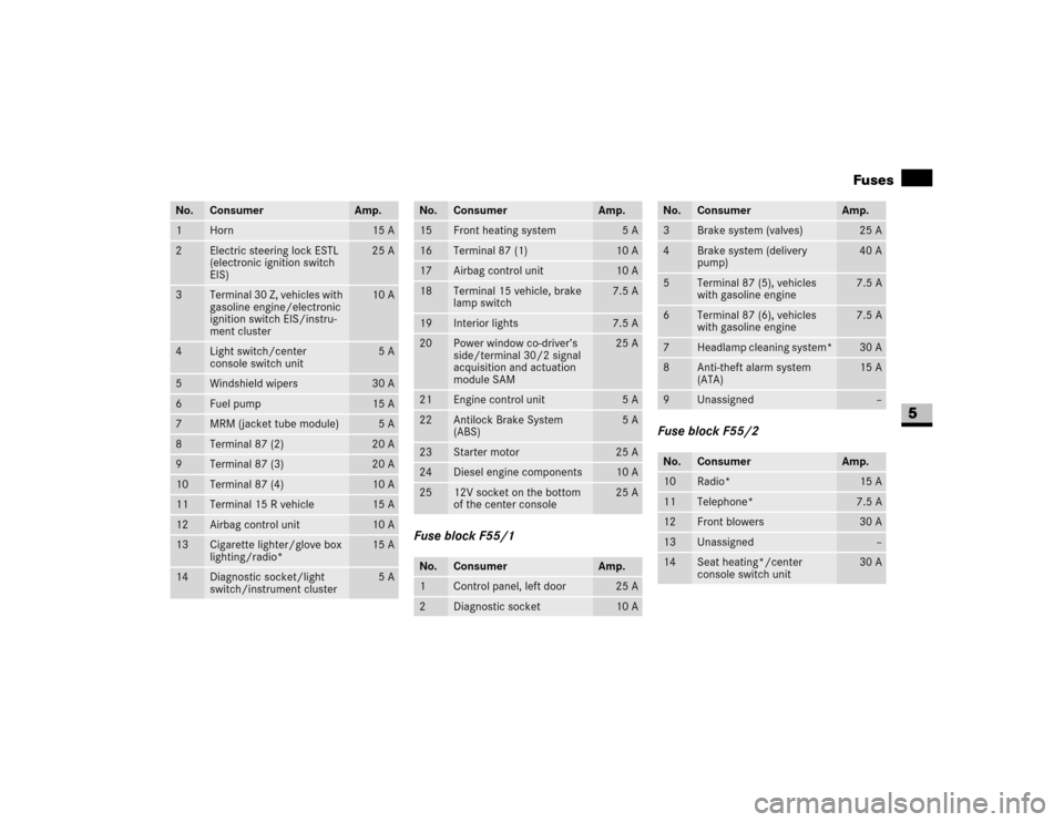
Fuse block F55/1Fuse block F55/2
No.
Consumer
Amp.
1
Horn
15 A
2
Electric steering lock ESTL
(electronic ignition switch
EIS)
25 A
3
Te rm ina l 30 Z , ve hi cle s wit h
gasoline engine/electronic
ignition switch EIS/instru-
ment cluster
10 A
4
Light switch/center
console switch unit
5A
5
Windshield wipers
30 A
6
Fuel pump
15 A
7
MRM (jacket tube module)
5A
8
Terminal 87 (2)
20 A
9
Terminal 87 (3)
20 A
10
Terminal 87 (4)
10 A
11
Terminal 15 R vehicle
15 A
12
Airbag control unit
10 A
13
Cigarette lighter/glove box
lighting/radio*
15 A
14
Diagnostic socket/light
switch/instrument cluster
5A
No.
Consumer
Amp.
15
Front heating system
5A
16
Terminal 87 (1)
10 A
17
Airbag control unit
10 A
18
Terminal 15 vehicle, brake
lamp switch
7.5 A
19
Interior lights
7.5 A
20
Power window co-driver’s
side/terminal 30/2 signal
acquisition and actuation
module SAM
25 A
21
Engine control unit
5A
22
Antilock Brake System
(ABS)
5A
23
Starter motor
25 A
24
Diesel engine components
10 A
25
12V socket on the bottom
of the center console
25 A
No.
Consumer
Amp.
1
Control panel, left door
25 A
2
Diagnostic socket
10 A
No.
Consumer
Amp.
3
Brake system (valves)
25 A
4
Brake system (delivery
pump)
40 A
5
Terminal 87 (5), vehicles
with gasoline engine
7.5 A
6
Terminal 87 (6), vehicles
with gasoline engine
7.5 A
7
Headlamp cleaning system*
30 A
8
Anti-theft alarm system
(ATA)
15 A
9
Unassigned
–
No.
Consumer
Amp.
10
Radio*
15 A
11
Telephone*
7.5 A
12
Front blowers
30 A
13
Unassigned
–
14
Seat heating*/center
console switch unit
30 A
Page 349 of 393
348 Practical hintsFuses
5
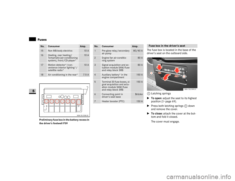
Preliminary fuse box in the battery recess in
the driver’s footwell F59
The fuse box is located in the base of the
driver’s seat on the outboard side.
1Latching springs
\1To open: adjust the seat to its highest
position (\2page 69).
\1Press both latching springs1 down
and remove the cover.
\1To close: attach the cover at the bot-
tom and fold it closed.
The cover must engage.
No.
Consumer
Amp.
15
Non MB-body electrics
10 A
16
Heating, rear heating/
Tempmatic (air-conditioning
system), front/CD-player*
10 A
17
Motion detector*/con-
venience interior lighting*/
satellite radio*
10 A
18
Air conditioning in the rear*
7.5 A
No.
Consumer
Amp.
1
Pre-glow relay/secondary
air pump
80/40 A
2
Engine fan air-conditio-
ning system
80 A
3
Signal acquisition and ac-
tuation module SAM/fuse
and relay block SRB
80 A
4
Auxiliary battery* in the
engine compartment
150 A
5
T erm in al 30 f us e bo xe s, si-
gnal acquisition and actu-
ation module SAM/fuse
and relay block SRB
150 A
6
Connecting point in
driver’s seat base
Brücke
7
Heater booster (PTC)
150 A
Fuse box in the driver’s seat
N54.15-2149-31
Page 353 of 393
352 *Technical dataGenuine Sprinter parts
6
\3 Genuine Sprinter parts The “Technical data” section contains im-
portant technical data regarding your vehi-
cle.
You will find other vehicle-specific and
equipment-dependent technical data, such
as:
\4engine power output data
\4speeds
\4vehicle dimensions
\4vehicle weights
in your vehicle documents.Make sure that spare parts are suitable for
your vehicle. Parts that constitute a modi-
fication to the vehicle by:
\4changing the type of vehicle approved
in the general operating permit,
\4creating a risk to road users or
\4having an adverse effect on the vehi-
cle’s emissions and noise levels,
will in many countries invalidate the gen-
eral operating permit. The use of non-
approved parts could have a detrimental
effect on road safety.Every authorized Sprinter Dealer maintains
a stock of genuine sprinter parts for main-
tenance and repair work.
Over 6000 retailers around the world guar-
antee that you can be supplied with genu-
ine sprinter parts wherever you are. Over
300,000 different parts and assemblies,
including parts for older vehicle models,
are distributed from a central parts ware-
house using an optimally tuned logistics
concept.
Page 354 of 393
353 *Technical data
Genuine Sprinter parts
6
Genuine sprinter parts are subjected to the
most stringent quality inspections and will
ensure that the vehicle is maintained at a
high level of operating efficiency and safe-
ty, and that it maintains its value. Each part
has been specifically designed and manu-
factured or selected and approved for use
in Sprinter vehicles.
It is therefore best to use only genuine
sprinter parts.For cost-effective repairs in accordance
with sound recycling principles, the use of
non-genuine parts and accessories not au-
thorized by the manufacturer could dam-
age the vehicle or compromise its
durability or safety.
You can obtain further information about
approved conversion parts and accesso-
ries and permitted technical modifications
from your authorized Sprinter Dealer.
Always quote the vehicle identification
number and the engine number when or-
dering genuine parts. You will find these
numbers on your vehicle’s identification la-
bels (\2page 373) and also on the vehicle
data card for certain vehicles.
Environmental note
H
The manufacturer also supplies recondi-
tioned assemblies and parts for cost-effec-
tive repairs in accordance with recycling
principles. These parts have the same quali-
ty and warranty as new parts.
Page 355 of 393
354 *Technical dataVehicle electronics
6
\3 Vehicle electronics
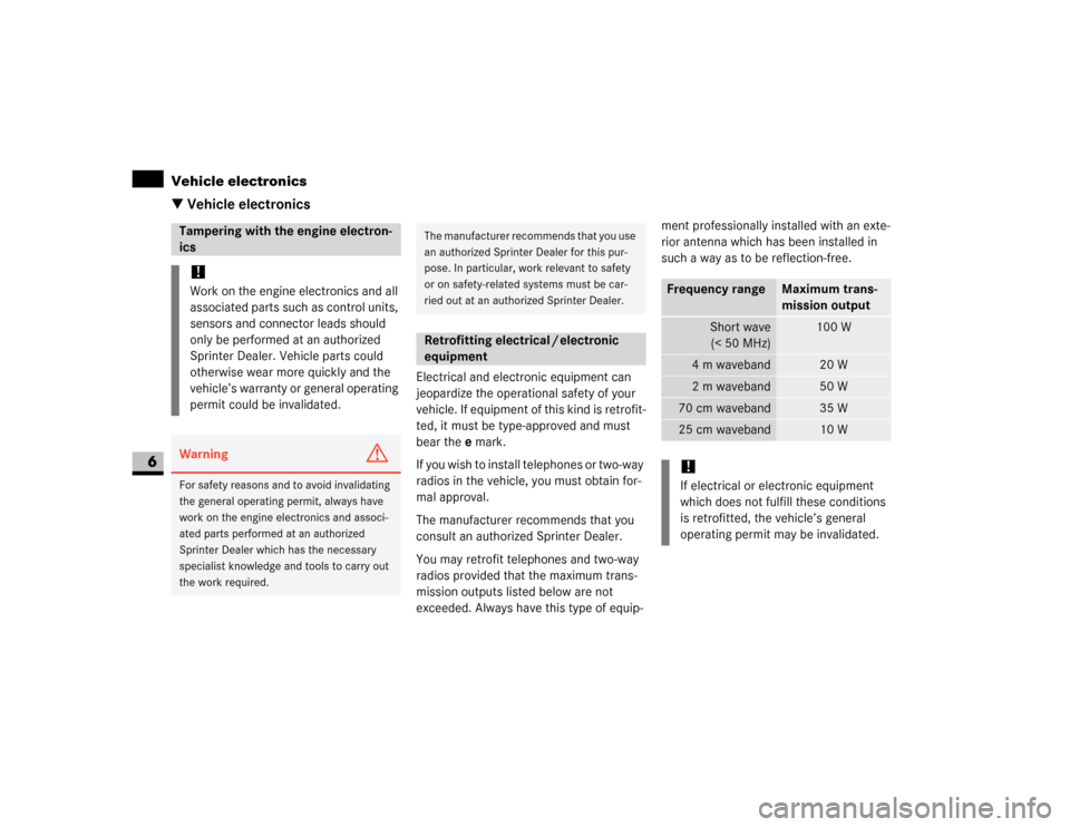
Electrical and electronic equipment can
jeopardize the operational safety of your
vehicle. If equipment of this kind is retrofit-
ted, it must be type-approved and must
bear the e mark.
If you wish to install telephones or two-way
radios in the vehicle, you must obtain for-
mal approval.
The manufacturer recommends that you
consult an authorized Sprinter Dealer.
You may retrofit telephones and two-way
radios provided that the maximum trans-
mission outputs listed below are not
exceeded. Always have this type of equip-ment professionally installed with an exte-
rior antenna which has been installed in
such a way as to be reflection-free.
.
Tampering with the engine electron-
ics !Work on the engine electronics and all
associated parts such as control units,
sensors and connector leads should
only be performed at an authorized
Sprinter Dealer. Vehicle parts could
otherwise wear more quickly and the
vehicle’s warranty or general operating
permit could be invalidated.Warning
G
For safety reasons and to avoid invalidating
the general operating permit, always have
work on the engine electronics and associ-
ated parts performed at an authorized
Sprinter Dealer which has the necessary
specialist knowledge and tools to carry out
the work required.
The manufacturer recommends that you use
an authorized Sprinter Dealer for this pur-
pose. In particular, work relevant to safety
or on safety-related systems must be car-
ried out at an authorized Sprinter Dealer.Retrofitting electrical / electronic
equipment
Frequency range
Maximum trans-
mission output
Short wave
(< 50 MHz)
100 W
4m waveband
20 W
2m waveband
50 W
70 cm waveband
35 W
25 cm waveband
10 W
!If electrical or electronic equipment
which does not fulfill these conditions
is retrofitted, the vehicle’s general
operating permit may be invalidated.
Page 356 of 393
355 *Technical data
Service products and capacities
6
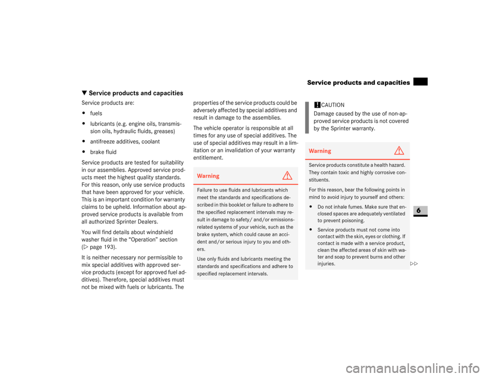
\3 Service products and capacitiesService products are:
\4fuels
\4lubricants (e.g. engine oils, transmis-
sion oils, hydraulic fluids, greases)
\4antifreeze additives, coolant
\4brake fluid
Service products are tested for suitability
in our assemblies. Approved service prod-
ucts meet the highest quality standards.
For this reason, only use service products
that have been approved for your vehicle.
This is an important condition for warranty
claims to be upheld. Information about ap-
proved service products is available from
all authorized Sprinter Dealers.
You will find details about windshield
washer fluid in the “Operation” section
(\2page 193).
It is neither necessary nor permissible to
mix special additives with approved ser-
vice products (except for approved fuel ad-
ditives). Therefore, special additives must
not be mixed with fuels or lubricants. The properties of the service products could be
adversely affected by special additives and
result in damage to the assemblies.
The vehicle operator is responsible at all
times for any use of special additives. The
use of special additives may result in a lim-
itation or an invalidation of your warranty
entitlement.
Warning
G
Failure to use fluids and lubricants which
meet the standards and specifications de-
scribed in this booklet or failure to adhere to
the specified replacement intervals may re-
sult in damage to safety/ and/or emissions-
related systems of your vehicle, such as the
brake system, which could cause an acci-
dent and/or serious injury to you and oth-
ers.
Use only fluids and lubricants meeting the
standards and specifications and adhere to
specified replacement intervals.
!
CAUTION
Damage caused by the use of non-ap-
proved service products is not covered
by the Sprinter warranty.
Warning
G
Service products constitute a health hazard.
They contain toxic and highly corrosive con-
stituents.
For this reason, bear the following points in
mind to avoid injury to yourself and others:
\4Do not inhale fumes. Make sure that en-
closed spaces are adequately ventilated
to prevent poisoning.
\4Service products must not come into
contact with the skin, eyes or clothing. If
contact is made with a service product,
clean the affected areas of skin with wa-
ter and soap to prevent burns and other
injuries.
\2\2