stop start DODGE SPRINTER 2007 2.G User Guide
[x] Cancel search | Manufacturer: DODGE, Model Year: 2007, Model line: SPRINTER, Model: DODGE SPRINTER 2007 2.GPages: 393, PDF Size: 7.61 MB
Page 330 of 393

329 Practical hints
Flat tire
5
\1Start the engine (\2page 111).
\1Press I on electric air pump switch1.
The electric air pump is switched on.
The tire sealant is then pumped into
the tire and the tire pressure is in-
creased. Allow the electric air pump to
run for at least 10 minutes until tire
sealant bottle 8 is completely empty
and a minimum tire pressure of
43.5 psi (3.0 bar) is achieved.
\1Inflate the tire using the electric air
pump until the recommended tire pres-
sure (\2page 210) is achieved.
\1Then press0 on electric air pump
switch1.
The electric air pump is switched off.
\1Slide knoba quickly to the stop in
valve core extractorc.
\1Turn knob a clockwise until the valve
core is firmly screwed into tire
valved.
\1Press leverb and remove valve core
extractorc from tire valved.
\1Screw the valve cap onto tire valved.
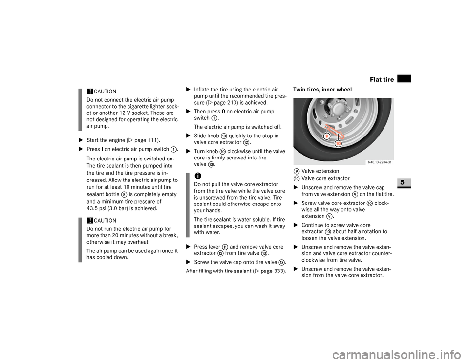
After filling with tire sealant (\2page 333).Twin tires, inner wheel
9Valve extension
aValve core extractor
\1Unscrew and remove the valve cap
from valve extension9 on the flat tire.
\1Screw valve core extractora clock-
wise all the way onto valve
extension9.
\1Continue to screw valve core
extractora about half a rotation to
loosen the valve extension.
\1Unscrew and remove the valve exten-
sion and valve core extractor counter-
clockwise from tire valve.
\1Unscrew and remove the valve exten-
sion from the valve core extractor.
!
CAUTION
Do not connect the electric air pump
connector to the cigarette lighter sock-
et or another 12 V socket. These are
not designed for operating the electric
air pump.
!
CAUTION
Do not run the electric air pump for
more than 20 minutes without a break,
otherwise it may overheat.
The air pump can be used again once it
has cooled down.
iDo not pull the valve core extractor
from the tire valve while the valve core
is unscrewed from the tire valve. Tire
sealant could otherwise escape onto
your hands.
The tire sealant is water soluble. If tire
sealant escapes, you can wash it away
with water.
Page 331 of 393

330 Practical hintsFlat tire
5
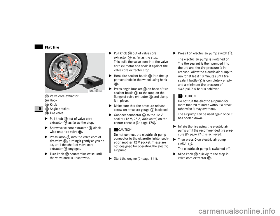
aValve core extractor
bHook
cKnob
dAngle bracket
eTire valve
\1Pull knob c out of valve core
extractora as far as the stop.
\1Screw valve core extractora clock-
wise onto tire valvee.
\1Press knob c into the valve core of
tire valvee, turning it gently as you do
so, until the shaft of valve core
extractora engages.
\1Turn knob c counterclockwise until
the valve core is unscrewed.\1Pull knob c out of valve core
extractora as far as the stop.
This pulls the valve core into the valve
core extractor and seals it against the
valve core extractor stop.
\1Hook tire sealant bottle 8 into the up-
per vent hole in the wheel using hook
b.
\1Press angle bracket d on hose of tire
sealant bottle 8 to the stop on the
flange of valve extractora and clamp
it in place.
\1Make sure that the pressure release
screw on pressure gauge 5 is closed.
\1Connect connector6 to the 12 V
socket (12 V, 25 A, 300 watts) on the
center console (\2page 170).
\1Start the engine (\2page 111).\1Press I on electric air pump switch1.
The electric air pump is switched on.
The tire sealant is then pumped into
the tire and the tire pressure is in-
creased. Allow the electric air pump to
run for at least 10 minutes until tire
sealant bottle 8 is completely empty
and a minimum tire pressure of
43.5 psi (3.0 bar) is achieved.
\1Inflate the tire using the electric air
pump until the recommended tire pres-
sure (\2page 210) is achieved.
\1Then press0 on electric air pump
switch1.
The electric air pump is switched off.
\1Slide knob c quickly to the stop in
valve core extractora.
!
CAUTION
Do not connect the electric air pump
connector to the cigarette lighter sock-
et or another 12 V socket. These are
not designed for operating the electric
air pump.
!
CAUTION
Do not run the electric air pump for
more than 20 minutes without a break,
otherwise it may overheat.
The air pump can be used again once it
has cooled down.
Page 333 of 393

332 Practical hintsFlat tire
5
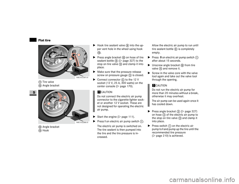
bTire valve
cAngle bracket
cAngle bracket
dHook\1Hook tire sealant valve 8 into the up-
per vent hole in the wheel using hook
d.
\1Press angle bracket c on hose of tire
sealant bottle 8 (\2page 327) to the
stop on tire valveb and clamp it into
place.
\1Make sure that the pressure release
screw on pressure gauge 5 is closed.
\1Connect connector6 to the 12 V
socket (12 V, 25 A, 300 watts) on the
center console (\2page 170).
\1Start the engine (\2page 111).
\1Press I on electric air pump switch1.
The electric air pump is switched on.
The tire sealant is then pumped into
the tire and the tire pressure is in-
creased.Allow the electric air pump to run until
tire sealant bottle 8 is completely
empty.
\1Press 0 on electric air pump switch1
after about 15 seconds.
\1Unscrew angle bracket c from tire
valveb and remove it.
\1Screw in the valve core with the valve
tool again and take out the valve tool
through the opening.
\1Press angle bracket 2 (\2page 327)
on hose 3 of the electric air pump to
the stop on tire valveb and clamp it
into place.
\1Press switch 1 on the electric air
pump to I and pump up the tire until the
recommended tire pressure
(\2page 210) is achieved.
!
CAUTION
Do not connect the electric air pump
connector to the cigarette lighter sock-
et or another 12 V socket. These are
not designed for operating the electric
air pump.
!
CAUTION
Do not run the electric air pump for
more than 20 minutes without a break,
otherwise it may overheat.
The air pump can be used again once it
has cooled down.
Page 379 of 393

378 Indexmaneuvering
. . . . . . . . . . . . . . . . . 124
one-touch gearshifting
. . . . . . . . . . 122
releasing the parking lock manually
305
selector lever positions
. . . . . . . . . 121
shift ranges
. . . . . . . . . . . . . . . . . . 123
stopping
. . . . . . . . . . . . . . . . . . . . . 124
towing
. . . . . . . . . . . . . . . . . . . . . . 343
trailer towing
. . . . . . . . . . . . . . . . . 124
working on the vehicle
. . . . . . . . . . 124
Auxiliary heating
. . . . . . . . . . . . . . . 139
heater booster function
. . . . . . . . . 137
malfunctions
. . . . . . . . . . . . . . . . . 264
with water heater
changing the remote control
batteries
. . . . . . . . . . . . . . . . . . . 316
remote control
. . . . . . . . . . . . . . 141
selecting a switch-on time
. . . . . 142
setting the switch-on time . . . . . 143
B
Bar
. . . . . . . . . . . . . . . . . . . . . . . . . . 228
BAS
see Brake Assist
Battery
auxiliary
. . . . . . . . . . . . . . . . . . . . . 337
charge indicator lamp
. . . . . . . . . . 273check lamp (auxiliary heating remote
control)
. . . . . . . . . . . . . . . . . . . . . 141
display message
. . . . . . . . . . . . . . . 289
in the auxiliary heating remote
control
. . . . . . . . . . . . . . . . . . . . . . 316
in the engine compartment
. . . . . . 337
in the key
. . . . . . . . . . . . . . . . . . . . 315
indicator lamp (key)
. . . . . . . . . . . . . 53
isolating switch
. . . . . . . . . . . . . . . 197
recharging
. . . . . . . . . . . . . . . . . . . 339
reconnecting . . . . . . . . . . . . . . . . . 339
removing
. . . . . . . . . . . . . . . . . . . . 337
safety notes . . . . . . . . . . . . . . . . . . 195
starter battery
disconnecting
. . . . . . . . . . . . . . . 336
Bead
. . . . . . . . . . . . . . . . . . . . . . . . . 228
Belt force limiters
. . . . . . . . . . . . . . . 30
Bi-xenon headlamps . . . . . . . . . . . . 307
driving abroad
. . . . . . . . . . . . . . . . 180
Body builder guideline
. . . . . . . . . . . . 6
Bottle holder
see Cup holders
Brake Assist (BAS)
. . . . . . . . . . . . . . 43
display message
. . . . . . . . . . . . . . . 291
indicator lamp
. . . . . . . 268
, 269
, 270
malfunction
. . . . . . . . . . . . . . . . . . 270Brake fluid
. . . . . . . . . . . . . . . . . . . . 362
checking the brake fluid level
. . . . 192
display message
. . . . . . . . . . . . . . . 290
Brake lamp
. . . . . . . . . . . . . . . . . . . . 309
changing bulbs
. . . . . . . . . . . . . . . . 310
high-mounted third brake lamp
. . . 309
Brake pads/linings
display message
. . . . . . . . . . . . . . . 289
wear indicator
. . . . . . . . . . . . . . . . 273
Brake system
brake pad/lining wear
indicator
. . . . . . . . . . . . . . . . . 273
, 289
indicator lamp
. . . . . . . . . . . . 268
–269
malfunction
. . . . . . . . . 270
, 271
, 291
Braking
driving tips
. . . . . . . . . . . . . . . . . . . 113
Breaking in . . . . . . . . . . . . . . . . . . . . 174
Bulbs
changing
see Changing bulbs
display message
. . . . . . . . . . . 292
, 293
C
Capacities
. . . . . . . . . . . . . . . . . . . . 365
Cards holder . . . . . . . . . . . . . . . . . . 165
Care
. . . . . . . . . . . . . . . . . . . . . . . . . 241
automatic car wash
. . . . . . . . . . . . 242
B
C