DODGE TOWN AND COUNTRY 2001 Service Manual
Manufacturer: DODGE, Model Year: 2001, Model line: TOWN AND COUNTRY, Model: DODGE TOWN AND COUNTRY 2001Pages: 2321, PDF Size: 68.09 MB
Page 1521 of 2321
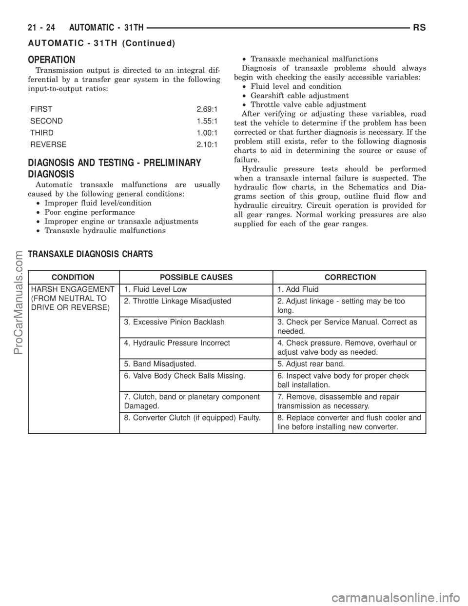
OPERATION
Transmission output is directed to an integral dif-
ferential by a transfer gear system in the following
input-to-output ratios:
FIRST 2.69:1
SECOND 1.55:1
THIRD 1.00:1
REVERSE 2.10:1
DIAGNOSIS AND TESTING - PRELIMINARY
DIAGNOSIS
Automatic transaxle malfunctions are usually
caused by the following general conditions:
²Improper fluid level/condition
²Poor engine performance
²Improper engine or transaxle adjustments
²Transaxle hydraulic malfunctions²Transaxle mechanical malfunctions
Diagnosis of transaxle problems should always
begin with checking the easily accessible variables:
²Fluid level and condition
²Gearshift cable adjustment
²Throttle valve cable adjustment
After verifying or adjusting these variables, road
test the vehicle to determine if the problem has been
corrected or that further diagnosis is necessary. If the
problem still exists, refer to the following diagnosis
charts to aid in determining the source or cause of
failure.
Hydraulic pressure tests should be performed
when a transaxle internal failure is suspected. The
hydraulic flow charts, in the Schematics and Dia-
grams section of this group, outline fluid flow and
hydraulic circuitry. Circuit operation is provided for
all gear ranges. Normal working pressures are also
supplied for each of the gear ranges.
TRANSAXLE DIAGNOSIS CHARTS
CONDITION POSSIBLE CAUSES CORRECTION
HARSH ENGAGEMENT
(FROM NEUTRAL TO
DRIVE OR REVERSE)1. Fluid Level Low 1. Add Fluid
2. Throttle Linkage Misadjusted 2. Adjust linkage - setting may be too
long.
3. Excessive Pinion Backlash 3. Check per Service Manual. Correct as
needed.
4. Hydraulic Pressure Incorrect 4. Check pressure. Remove, overhaul or
adjust valve body as needed.
5. Band Misadjusted. 5. Adjust rear band.
6. Valve Body Check Balls Missing. 6. Inspect valve body for proper check
ball installation.
7. Clutch, band or planetary component
Damaged.7. Remove, disassemble and repair
transmission as necessary.
8. Converter Clutch (if equipped) Faulty. 8. Replace converter and flush cooler and
line before installing new converter.
21 - 24 AUTOMATIC - 31THRS
AUTOMATIC - 31TH (Continued)
ProCarManuals.com
Page 1522 of 2321
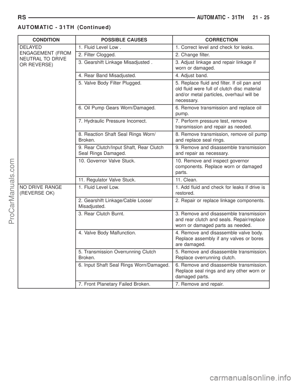
CONDITION POSSIBLE CAUSES CORRECTION
DELAYED
ENGAGEMENT (FROM
NEUTRAL TO DRIVE
OR REVERSE)1. Fluid Level Low . 1. Correct level and check for leaks.
2. Filter Clogged. 2. Change filter.
3. Gearshift Linkage Misadjusted . 3. Adjust linkage and repair linkage if
worn or damaged.
4. Rear Band Misadjusted. 4. Adjust band.
5. Valve Body Filter Plugged. 5. Replace fluid and filter. If oil pan and
old fluid were full of clutch disc material
and/or metal particles, overhaul will be
necessary.
6. Oil Pump Gears Worn/Damaged. 6. Remove transmission and replace oil
pump.
7. Hydraulic Pressure Incorrect. 7. Perform pressure test, remove
transmission and repair as needed.
8. Reaction Shaft Seal Rings Worn/
Broken.8. Remove transmission, remove oil pump
and replace seal rings.
9. Rear Clutch/Input Shaft, Rear Clutch
Seal Rings Damaged.9. Remove and disassemble transmission
and repair as necessary.
10. Governor Valve Stuck. 10. Remove and inspect governor
components. Replace worn or damaged
parts.
11. Regulator Valve Stuck. 11. Clean.
NO DRIVE RANGE
(REVERSE OK)1. Fluid Level Low. 1. Add fluid and check for leaks if drive is
restored.
2. Gearshift Linkage/Cable Loose/
Misadjusted.2. Repair or replace linkage components.
3. Rear Clutch Burnt. 3. Remove and disassemble transmission
and rear clutch and seals. Repair/replace
worn or damaged parts as needed.
4. Valve Body Malfunction. 4. Remove and disassemble valve body.
Replace assembly if any valves or bores
are damaged.
5. Transmission Overrunning Clutch
Broken.5. Remove and disassemble transmission.
Replace overrunning clutch.
6. Input Shaft Seal Rings Worn/Damaged. 6. Remove and disassemble transmission.
Replace seal rings and any other worn or
damaged parts.
7. Front Planetary Failed Broken. 7. Remove and repair.
RSAUTOMATIC - 31TH21-25
AUTOMATIC - 31TH (Continued)
ProCarManuals.com
Page 1523 of 2321
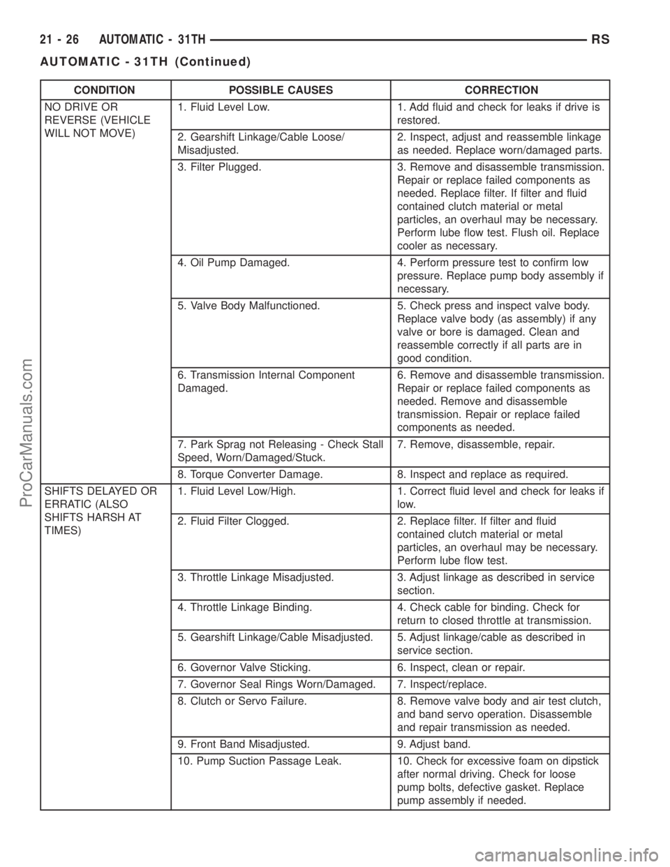
CONDITION POSSIBLE CAUSES CORRECTION
NO DRIVE OR
REVERSE (VEHICLE
WILL NOT MOVE)1. Fluid Level Low. 1. Add fluid and check for leaks if drive is
restored.
2. Gearshift Linkage/Cable Loose/
Misadjusted.2. Inspect, adjust and reassemble linkage
as needed. Replace worn/damaged parts.
3. Filter Plugged. 3. Remove and disassemble transmission.
Repair or replace failed components as
needed. Replace filter. If filter and fluid
contained clutch material or metal
particles, an overhaul may be necessary.
Perform lube flow test. Flush oil. Replace
cooler as necessary.
4. Oil Pump Damaged. 4. Perform pressure test to confirm low
pressure. Replace pump body assembly if
necessary.
5. Valve Body Malfunctioned. 5. Check press and inspect valve body.
Replace valve body (as assembly) if any
valve or bore is damaged. Clean and
reassemble correctly if all parts are in
good condition.
6. Transmission Internal Component
Damaged.6. Remove and disassemble transmission.
Repair or replace failed components as
needed. Remove and disassemble
transmission. Repair or replace failed
components as needed.
7. Park Sprag not Releasing - Check Stall
Speed, Worn/Damaged/Stuck.7. Remove, disassemble, repair.
8. Torque Converter Damage. 8. Inspect and replace as required.
SHIFTS DELAYED OR
ERRATIC (ALSO
SHIFTS HARSH AT
TIMES)1. Fluid Level Low/High. 1. Correct fluid level and check for leaks if
low.
2. Fluid Filter Clogged. 2. Replace filter. If filter and fluid
contained clutch material or metal
particles, an overhaul may be necessary.
Perform lube flow test.
3. Throttle Linkage Misadjusted. 3. Adjust linkage as described in service
section.
4. Throttle Linkage Binding. 4. Check cable for binding. Check for
return to closed throttle at transmission.
5. Gearshift Linkage/Cable Misadjusted. 5. Adjust linkage/cable as described in
service section.
6. Governor Valve Sticking. 6. Inspect, clean or repair.
7. Governor Seal Rings Worn/Damaged. 7. Inspect/replace.
8. Clutch or Servo Failure. 8. Remove valve body and air test clutch,
and band servo operation. Disassemble
and repair transmission as needed.
9. Front Band Misadjusted. 9. Adjust band.
10. Pump Suction Passage Leak. 10. Check for excessive foam on dipstick
after normal driving. Check for loose
pump bolts, defective gasket. Replace
pump assembly if needed.
21 - 26 AUTOMATIC - 31THRS
AUTOMATIC - 31TH (Continued)
ProCarManuals.com
Page 1524 of 2321
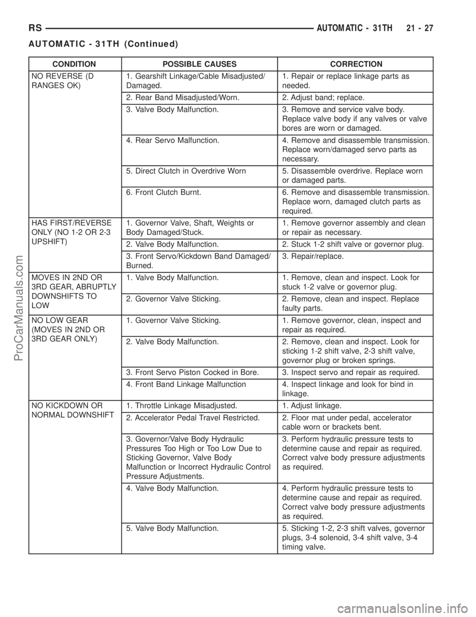
CONDITION POSSIBLE CAUSES CORRECTION
NO REVERSE (D
RANGES OK)1. Gearshift Linkage/Cable Misadjusted/
Damaged.1. Repair or replace linkage parts as
needed.
2. Rear Band Misadjusted/Worn. 2. Adjust band; replace.
3. Valve Body Malfunction. 3. Remove and service valve body.
Replace valve body if any valves or valve
bores are worn or damaged.
4. Rear Servo Malfunction. 4. Remove and disassemble transmission.
Replace worn/damaged servo parts as
necessary.
5. Direct Clutch in Overdrive Worn 5. Disassemble overdrive. Replace worn
or damaged parts.
6. Front Clutch Burnt. 6. Remove and disassemble transmission.
Replace worn, damaged clutch parts as
required.
HAS FIRST/REVERSE
ONLY (NO 1-2 OR 2-3
UPSHIFT)1. Governor Valve, Shaft, Weights or
Body Damaged/Stuck.1. Remove governor assembly and clean
or repair as necessary.
2. Valve Body Malfunction. 2. Stuck 1-2 shift valve or governor plug.
3. Front Servo/Kickdown Band Damaged/
Burned.3. Repair/replace.
MOVES IN 2ND OR
3RD GEAR, ABRUPTLY
DOWNSHIFTS TO
LOW1. Valve Body Malfunction. 1. Remove, clean and inspect. Look for
stuck 1-2 valve or governor plug.
2. Governor Valve Sticking. 2. Remove, clean and inspect. Replace
faulty parts.
NO LOW GEAR
(MOVES IN 2ND OR
3RD GEAR ONLY)1. Governor Valve Sticking. 1. Remove governor, clean, inspect and
repair as required.
2. Valve Body Malfunction. 2. Remove, clean and inspect. Look for
sticking 1-2 shift valve, 2-3 shift valve,
governor plug or broken springs.
3. Front Servo Piston Cocked in Bore. 3. Inspect servo and repair as required.
4. Front Band Linkage Malfunction 4. Inspect linkage and look for bind in
linkage.
NO KICKDOWN OR
NORMAL DOWNSHIFT1. Throttle Linkage Misadjusted. 1. Adjust linkage.
2. Accelerator Pedal Travel Restricted. 2. Floor mat under pedal, accelerator
cable worn or brackets bent.
3. Governor/Valve Body Hydraulic
Pressures Too High or Too Low Due to
Sticking Governor, Valve Body
Malfunction or Incorrect Hydraulic Control
Pressure Adjustments.3. Perform hydraulic pressure tests to
determine cause and repair as required.
Correct valve body pressure adjustments
as required.
4. Valve Body Malfunction. 4. Perform hydraulic pressure tests to
determine cause and repair as required.
Correct valve body pressure adjustments
as required.
5. Valve Body Malfunction. 5. Sticking 1-2, 2-3 shift valves, governor
plugs, 3-4 solenoid, 3-4 shift valve, 3-4
timing valve.
RSAUTOMATIC - 31TH21-27
AUTOMATIC - 31TH (Continued)
ProCarManuals.com
Page 1525 of 2321
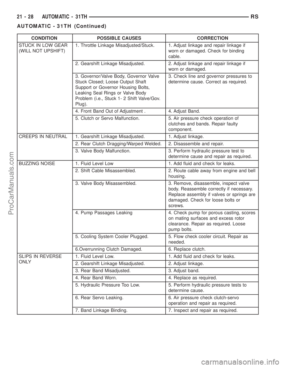
CONDITION POSSIBLE CAUSES CORRECTION
STUCK IN LOW GEAR
(WILL NOT UPSHIFT)1. Throttle Linkage Misadjusted/Stuck. 1. Adjust linkage and repair linkage if
worn or damaged. Check for binding
cable.
2. Gearshift Linkage Misadjusted. 2. Adjust linkage and repair linkage if
worn or damaged.
3. Governor/Valve Body, Governor Valve
Stuck Closed; Loose Output Shaft
Support or Governor Housing Bolts,
Leaking Seal Rings or Valve Body
Problem (i.e., Stuck 1- 2 Shift Valve/Gov.
Plug).3. Check line and governor pressures to
determine cause. Correct as required.
4. Front Band Out of Adjustment . 4. Adjust Band.
5. Clutch or Servo Malfunction. 5. Air pressure check operation of
clutches and bands. Repair faulty
component.
CREEPS IN NEUTRAL 1. Gearshift Linkage Misadjusted. 1. Adjust linkage.
2. Rear Clutch Dragging/Warped Welded. 2. Disassemble and repair.
3. Valve Body Malfunction. 3. Perform hydraulic pressure test to
determine cause and repair as required.
BUZZING NOISE 1. Fluid Level Low 1. Add fluid and check for leaks.
2. Shift Cable Misassembled. 2. Route cable away from engine and bell
housing.
3. Valve Body Misassembled. 3. Remove, disassemble, inspect valve
body. Reassemble correctly if necessary.
Replace assembly if valves or springs are
damaged. Check for loose bolts or
screws.
4. Pump Passages Leaking 4. Check pump for porous casting, scores
on mating surfaces and excess rotor
clearance. Repair as required. Loose
pump bolts.
5. Cooling System Cooler Plugged. 5. Flow check cooler circuit. Repair as
needed.
6.Overrunning Clutch Damaged. 6. Replace clutch.
SLIPS IN REVERSE
ONLY1. Fluid Level Low. 1. Add fluid and check for leaks.
2. Gearshift Linkage Misadjusted. 2. Adjust linkage.
3. Rear Band Misadjusted. 3. Adjust band.
4. Rear Band Worn. 4. Replace as required.
5. Hydraulic Pressure Too Low. 5. Perform hydraulic pressure tests to
determine cause.
6. Rear Servo Leaking. 6. Air pressure check clutch-servo
operation and repair as required.
7. Band Linkage Binding. 7. Inspect and repair as required.
21 - 28 AUTOMATIC - 31THRS
AUTOMATIC - 31TH (Continued)
ProCarManuals.com
Page 1526 of 2321
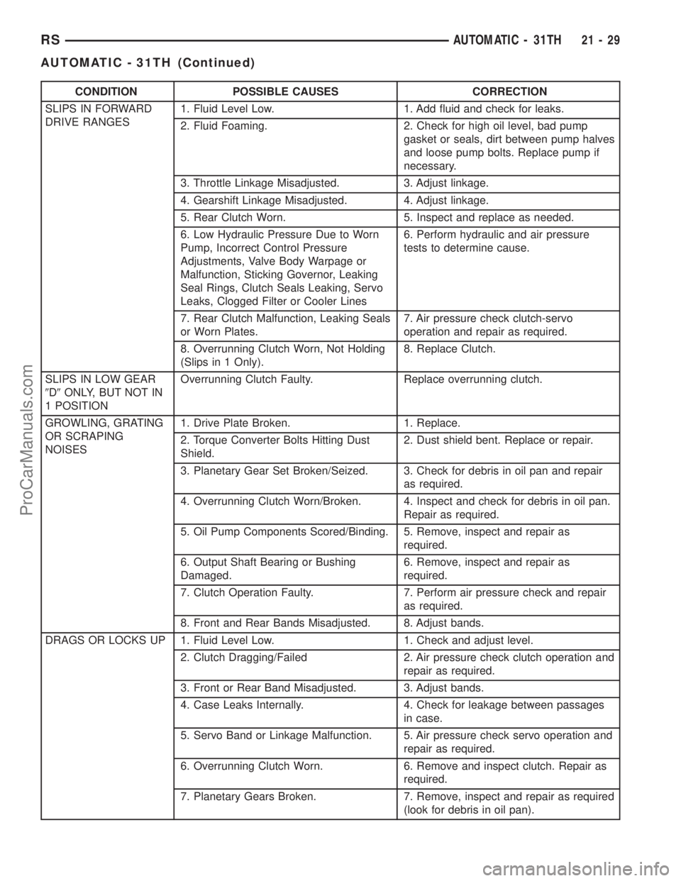
CONDITION POSSIBLE CAUSES CORRECTION
SLIPS IN FORWARD
DRIVE RANGES1. Fluid Level Low. 1. Add fluid and check for leaks.
2. Fluid Foaming. 2. Check for high oil level, bad pump
gasket or seals, dirt between pump halves
and loose pump bolts. Replace pump if
necessary.
3. Throttle Linkage Misadjusted. 3. Adjust linkage.
4. Gearshift Linkage Misadjusted. 4. Adjust linkage.
5. Rear Clutch Worn. 5. Inspect and replace as needed.
6. Low Hydraulic Pressure Due to Worn
Pump, Incorrect Control Pressure
Adjustments, Valve Body Warpage or
Malfunction, Sticking Governor, Leaking
Seal Rings, Clutch Seals Leaking, Servo
Leaks, Clogged Filter or Cooler Lines6. Perform hydraulic and air pressure
tests to determine cause.
7. Rear Clutch Malfunction, Leaking Seals
or Worn Plates.7. Air pressure check clutch-servo
operation and repair as required.
8. Overrunning Clutch Worn, Not Holding
(Slips in 1 Only).8. Replace Clutch.
SLIPS IN LOW GEAR
9D9ONLY, BUT NOT IN
1 POSITIONOverrunning Clutch Faulty. Replace overrunning clutch.
GROWLING, GRATING
OR SCRAPING
NOISES1. Drive Plate Broken. 1. Replace.
2. Torque Converter Bolts Hitting Dust
Shield.2. Dust shield bent. Replace or repair.
3. Planetary Gear Set Broken/Seized. 3. Check for debris in oil pan and repair
as required.
4. Overrunning Clutch Worn/Broken. 4. Inspect and check for debris in oil pan.
Repair as required.
5. Oil Pump Components Scored/Binding. 5. Remove, inspect and repair as
required.
6. Output Shaft Bearing or Bushing
Damaged.6. Remove, inspect and repair as
required.
7. Clutch Operation Faulty. 7. Perform air pressure check and repair
as required.
8. Front and Rear Bands Misadjusted. 8. Adjust bands.
DRAGS OR LOCKS UP 1. Fluid Level Low. 1. Check and adjust level.
2. Clutch Dragging/Failed 2. Air pressure check clutch operation and
repair as required.
3. Front or Rear Band Misadjusted. 3. Adjust bands.
4. Case Leaks Internally. 4. Check for leakage between passages
in case.
5. Servo Band or Linkage Malfunction. 5. Air pressure check servo operation and
repair as required.
6. Overrunning Clutch Worn. 6. Remove and inspect clutch. Repair as
required.
7. Planetary Gears Broken. 7. Remove, inspect and repair as required
(look for debris in oil pan).
RSAUTOMATIC - 31TH21-29
AUTOMATIC - 31TH (Continued)
ProCarManuals.com
Page 1527 of 2321
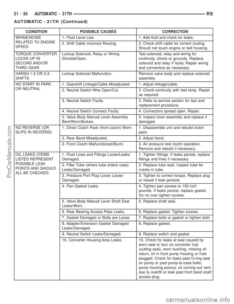
CONDITION POSSIBLE CAUSES CORRECTION
WHINE/NOISE
RELATED TO ENGINE
SPEED1. Fluid Level Low. 1. Add fluid and check for leaks.
2. Shift Cable Incorrect Routing. 2. Check shift cable for correct routing.
Should not touch engine or bell housing.
TORQUE CONVERTER
LOCKS UP IN
SECOND AND/OR
THIRD GEARLockup Solenoid, Relay or Wiring
Shorted/Open.Test solenoid, relay and wiring for
continuity, shorts or grounds. Replace
solenoid and relay if faulty. Repair wiring
and connectors as necessary.
HARSH 1-2 OR 2-3
SHIFTSLockup Solenoid Malfunction. Remove valve body and replace solenoid
assembly.
NO START IN PARK
OR NEUTRAL1. Gearshift Linkage/Cable Misadjusted. 1. Adjust linkage/cable.
2. Neutral Switch Wire Open/Cut. 2. Check continuity with test lamp. Repair
as required.
3. Neutral Switch Faulty. 3. Refer to service section for test and
replacement procedure.
4. Neutral Switch Connect Faulty. 4. Connectors spread open. Repair.
5. Valve Body Manual Lever Assembly
Bent/Worn/Broken.5. Inspect lever assembly and replace if
damaged.
NO REVERSE (OR
SLIPS IN REVERSE)1. Direct Clutch Pack (front clutch) Worn. 1. Disassemble unit and rebuild clutch
pack.
2. Rear Band Misadjusted. 2. Adjust band.
3. Front Clutch Malfunctioned/Burnt. 3. Air pressure test clutch operation.
Remove and rebuild if necessary.
OIL LEAKS (ITEMS
LISTED REPRESENT
POSSIBLE LEAK
POINTS AND SHOULD
ALL BE CHECKED.1. Fluid Lines and Fittings Loose/Leaks/
Damaged.1. Tighten fittings. If leaks persist, replace
fittings and lines if necessary.
2. Filler Tube (where tube enters case)
Leaks/Damaged.2. Replace tube seal. Inspect tube for
cracks in tube.
3. Pressure Port Plug Loose Loose/
Damaged.3. Tighten to correct torque. Replace plug
or reseal if leak persists.
4. Pan Gasket Leaks. 4. Tighten pan screws to 150 inch
pounds. If leaks persist, replace gasket.
Do no over tighten screws.
5. Valve Body Manual Lever Shaft Seal
Leaks/Worn.5. Replace shaft seal.
6. Rear Bearing Access Plate Leaks. 6. Replace gasket. Tighten screws.
7. Gasket Damaged or Bolts are Loose. 7. Replace bolts or gasket or tighten both.
8. Adapter/Extension Gasket Damaged
Leaks/Damaged.8. Replace gasket.
9. Neutral Switch Leaks/Damaged. 9. Replace switch and gasket.
10. Converter Housing Area Leaks. 10. Check for leaks at seal caused by
worn seal or burr on converter hub
(cutting seal), worn bushing, missing oil
return, oil in front pump housing or hole
plugged. Check for leaks past O-ring seal
on pump or past pump-to-case bolts;
pump housing porous, oil coming out vent
due to overfill or leak past front band shaft
access plug.
21 - 30 AUTOMATIC - 31THRS
AUTOMATIC - 31TH (Continued)
ProCarManuals.com
Page 1528 of 2321
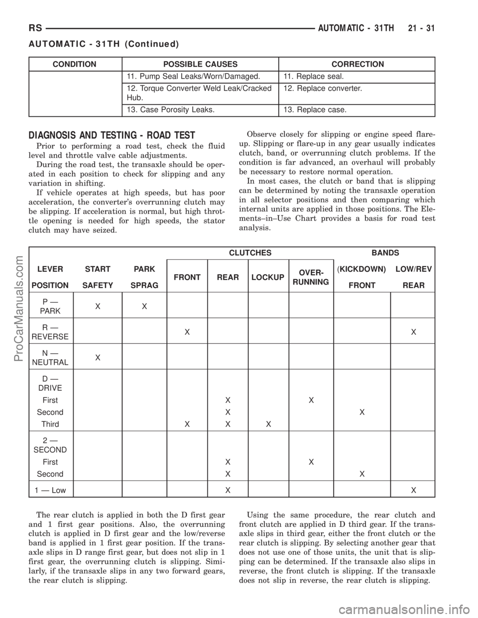
CONDITION POSSIBLE CAUSES CORRECTION
11. Pump Seal Leaks/Worn/Damaged. 11. Replace seal.
12. Torque Converter Weld Leak/Cracked
Hub.12. Replace converter.
13. Case Porosity Leaks. 13. Replace case.
DIAGNOSIS AND TESTING - ROAD TEST
Prior to performing a road test, check the fluid
level and throttle valve cable adjustments.
During the road test, the transaxle should be oper-
ated in each position to check for slipping and any
variation in shifting.
If vehicle operates at high speeds, but has poor
acceleration, the converter's overrunning clutch may
be slipping. If acceleration is normal, but high throt-
tle opening is needed for high speeds, the stator
clutch may have seized.Observe closely for slipping or engine speed flare-
up. Slipping or flare-up in any gear usually indicates
clutch, band, or overrunning clutch problems. If the
condition is far advanced, an overhaul will probably
be necessary to restore normal operation.
In most cases, the clutch or band that is slipping
can be determined by noting the transaxle operation
in all selector positions and then comparing which
internal units are applied in those positions. The Ele-
ments±in±Use Chart provides a basis for road test
analysis.
CLUTCHES BANDS
LEVER START PARK
FRONT REAR LOCKUPOVER-
RUNNING(KICKDOWN) LOW/REV
POSITION SAFETY SPRAG FRONT REAR
PÐ
PARKXX
RÐ
REVERSEXX
NÐ
NEUTRALX
DÐ
DRIVE
First X X
Second X X
Third X X X
2Ð
SECOND
First X X
Second X X
1 Ð Low X X
The rear clutch is applied in both the D first gear
and 1 first gear positions. Also, the overrunning
clutch is applied in D first gear and the low/reverse
band is applied in 1 first gear position. If the trans-
axle slips in D range first gear, but does not slip in 1
first gear, the overrunning clutch is slipping. Simi-
larly, if the transaxle slips in any two forward gears,
the rear clutch is slipping.Using the same procedure, the rear clutch and
front clutch are applied in D third gear. If the trans-
axle slips in third gear, either the front clutch or the
rear clutch is slipping. By selecting another gear that
does not use one of those units, the unit that is slip-
ping can be determined. If the transaxle also slips in
reverse, the front clutch is slipping. If the transaxle
does not slip in reverse, the rear clutch is slipping.
RSAUTOMATIC - 31TH21-31
AUTOMATIC - 31TH (Continued)
ProCarManuals.com
Page 1529 of 2321
The process of elimination can be used to detect
any unit that slips and to confirm proper operation of
good units. Road testing can usually diagnose slip-
ping units, although the actual cause of the problem
may not be detected. Practically any condition can be
caused by leaking hydraulic circuits or sticking
valves.
Therefore, unless the condition is obvious, the
transaxle should never be disassembled until hydrau-
lic pressure tests have been performed.DIAGNOSIS AND TESTING - HYDRAULIC
PRESSURE TESTS
Pressure testing is a very important step in the
diagnostic procedure. These tests usually reveal the
cause of most transaxle problems.
Before performing pressure tests, check fluid level
and condition, as well as control cable adjustments.
Fluid must be at operating temperature (150-200
degrees F.).
Install an engine tachometer. Raise vehicle on a
hoist that allows front wheels to turn, and position
tachometer so it can be read.
Disconnect throttle cable and shift cable from
transaxle levers so they can be controlled from out-
side the vehicle.
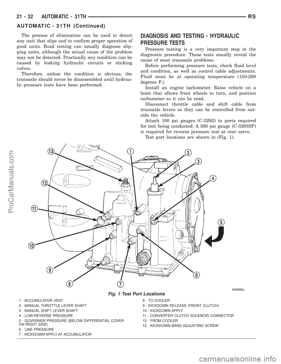
Attach 100 psi gauges (C-3292) to ports required
for test being conducted. A 300 psi gauge (C-3293SP)
is required for reverse pressure test at rear servo.
Test port locations are shown in (Fig. 1).
Fig. 1 Test Port Locations
1 - ACCUMULATOR VENT
2 - MANUAL THROTTLE LEVER SHAFT
3 - MANUAL SHIFT LEVER SHAFT
4 - LOW-REVERSE PRESSURE
5 - GOVERNER PRESSURE (BELOW DIFFERENTIAL COVER
ON RIGHT SIDE)
6 - LINE PRESSURE
7 - KICKDOWN APPLY AT ACCUMULATOR8 - TO COOLER
9 - KICKDOWN RELEASE (FRONT CLUTCH)
10 - KICKDOWN APPLY
11 - CONVERTER CLUTCH SOLENOID CONNECTOR
12 - FROM COOLER
13 - KICKDOWN BAND ADJUSTING SCREW
21 - 32 AUTOMATIC - 31THRS
AUTOMATIC - 31TH (Continued)
ProCarManuals.com
Page 1530 of 2321
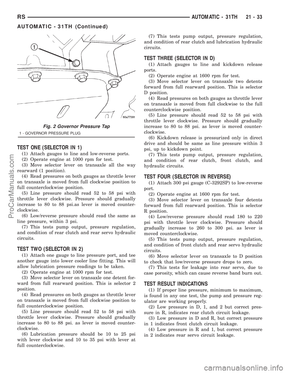
TEST ONE (SELECTOR IN 1)
(1) Attach gauges to line and low-reverse ports.
(2) Operate engine at 1000 rpm for test.
(3) Move selector lever on transaxle all the way
rearward (1 position).
(4) Read pressures on both gauges as throttle lever
on transaxle is moved from full clockwise position to
full counterclockwise position.
(5) Line pressure should read 52 to 58 psi with
throttle lever clockwise. Pressure should gradually
increase to 80 to 88 psi.as lever is moved counter-
clockwise.
(6) Low/reverse pressure should read the same as
line pressure, within 3 psi.
(7) This tests pump output, pressure regulation,
and condition of rear clutch and rear servo hydraulic
circuits.
TEST TWO (SELECTOR IN 2)
(1) Attach one gauge to line pressure port, and tee
another gauge into lower cooler line fitting. This will
allow lubrication pressure readings to be taken.
(2) Operate engine at 1000 rpm for test.
(3) Move selector lever on transaxle one detent for-
ward from full rearward position. This is selector 2
position.
(4) Read pressures on both gauges as throttle lever
on transaxle is moved from full clockwise position to
full counterclockwise position.
(5) Line pressure should read 52 to 58 psi with
throttle lever clockwise. Pressure should gradually
increase to 80 to 88 psi. as lever is moved counter-
clockwise.
(6) Lubrication pressure should be 10 to 25 psi
with lever clockwise and 10 to 35 psi with lever at
full counterclockwise.(7) This tests pump output, pressure regulation,
and condition of rear clutch and lubrication hydraulic
circuits.
TEST THREE (SELECTOR IN D)
(1) Attach gauges to line and kickdown release
ports.
(2) Operate engine at 1600 rpm for test.
(3) Move selector lever on transaxle two detents
forward from full rearward position. This is selector
D position.
(4) Read pressures on both gauges as throttle lever
on transaxle is moved from full clockwise to the full
counterclockwise position.
(5) Line pressure should read 52 to 58 psi with
throttle lever clockwise. Pressure should gradually
increase to 80 to 88 psi. as lever is moved counter-
clockwise.
(6) Kickdown release is pressurized only in direct
drive and should be same as line pressure within 3
psi, up to kickdown point.
(7) This tests pump output, pressure regulation,
and condition of rear clutch, front clutch, and
hydraulic circuits.
TEST FOUR (SELECTOR IN REVERSE)
(1) Attach 300 psi gauge (C-3292SP) to low-reverse
port.
(2) Operate engine at 1600 rpm for test.
(3) Move selector lever on transaxle four detents
forward from full rearward position. This is selector
R position.
(4) Low/reverse pressure should read 180 to 220
psi with throttle lever clockwise. Pressure should
gradually increase to 260 to 300 psi. as lever is
moved counterclockwise.
(5) This tests pump output, pressure regulation,
and condition of front clutch and rear servo hydraulic
circuits.
(6) Move selector lever on transaxle to D position
to check that low/reverse pressure drops to zero.
(7) This tests for leakage into rear servo, due to
case porosity, which can cause reverse band burn out.
TEST RESULT INDICATIONS
(1) If proper line pressure, minimum to maximum,
is found in any one test, the pump and pressure reg-
ulator are working properly.
(2) Low pressure in D, 1, and 2 but correct pres-
sure in R, indicates rear clutch circuit leakage.
(3) Low pressure in D and R, but correct pressure
in 1 indicates front clutch circuit leakage.
(4) Low pressure in R and 1, but correct pressure
in 2 indicates rear servo circuit leakage.
Fig. 2 Governor Pressure Tap
1 - GOVERNOR PRESSURE PLUG
RSAUTOMATIC - 31TH21-33
AUTOMATIC - 31TH (Continued)
ProCarManuals.com