DODGE TOWN AND COUNTRY 2001 Service Manual
Manufacturer: DODGE, Model Year: 2001, Model line: TOWN AND COUNTRY, Model: DODGE TOWN AND COUNTRY 2001Pages: 2321, PDF Size: 68.09 MB
Page 1541 of 2321
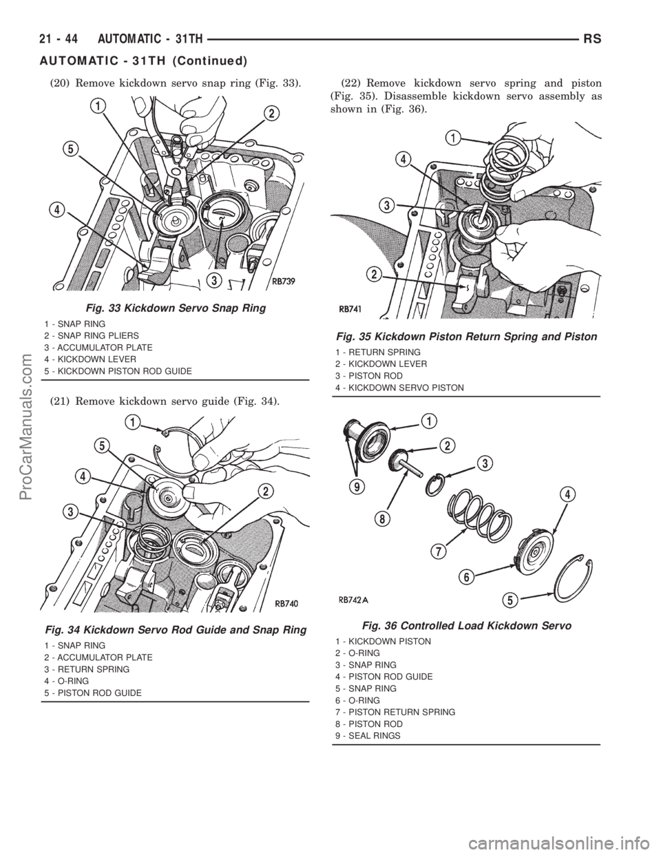
(20) Remove kickdown servo snap ring (Fig. 33).
(21) Remove kickdown servo guide (Fig. 34).(22) Remove kickdown servo spring and piston
(Fig. 35). Disassemble kickdown servo assembly as
shown in (Fig. 36).
Fig. 33 Kickdown Servo Snap Ring
1 - SNAP RING
2 - SNAP RING PLIERS
3 - ACCUMULATOR PLATE
4 - KICKDOWN LEVER
5 - KICKDOWN PISTON ROD GUIDE
Fig. 34 Kickdown Servo Rod Guide and Snap Ring
1 - SNAP RING
2 - ACCUMULATOR PLATE
3 - RETURN SPRING
4 - O-RING
5 - PISTON ROD GUIDE
Fig. 35 Kickdown Piston Return Spring and Piston
1 - RETURN SPRING
2 - KICKDOWN LEVER
3 - PISTON ROD
4 - KICKDOWN SERVO PISTON
Fig. 36 Controlled Load Kickdown Servo
1 - KICKDOWN PISTON
2 - O-RING
3 - SNAP RING
4 - PISTON ROD GUIDE
5 - SNAP RING
6 - O-RING
7 - PISTON RETURN SPRING
8 - PISTON ROD
9 - SEAL RINGS
21 - 44 AUTOMATIC - 31THRS
AUTOMATIC - 31TH (Continued)
ProCarManuals.com
Page 1542 of 2321
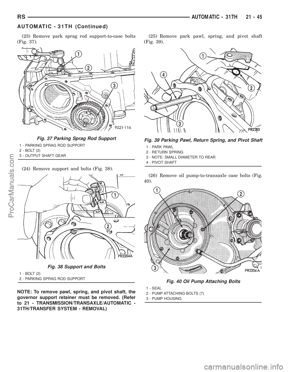
(23) Remove park sprag rod support-to-case bolts
(Fig. 37).
(24) Remove support and bolts (Fig. 38).
NOTE: To remove pawl, spring, and pivot shaft, the
governor support retainer must be removed. (Refer
to 21 - TRANSMISSION/TRANSAXLE/AUTOMATIC -
31TH/TRANSFER SYSTEM - REMOVAL)(25) Remove park pawl, spring, and pivot shaft
(Fig. 39).
(26) Remove oil pump-to-transaxle case bolts (Fig.
40).
Fig. 37 Parking Sprag Rod Support
1 - PARKING SPRAG ROD SUPPORT
2 - BOLT (2)
3 - OUTPUT SHAFT GEAR
Fig. 38 Support and Bolts
1 - BOLT (2)
2 - PARKING SPRAG ROD SUPPORT
Fig. 39 Parking Pawl, Return Spring, and Pivot Shaft
1 - PARK PAWL
2 - RETURN SPRING
3 - NOTE: SMALL DIAMETER TO REAR
4 - PIVOT SHAFT
Fig. 40 Oil Pump Attaching Bolts
1 - SEAL
2 - PUMP ATTACHING BOLTS (7)
3 - PUMP HOUSING
RSAUTOMATIC - 31TH21-45
AUTOMATIC - 31TH (Continued)
ProCarManuals.com
Page 1543 of 2321
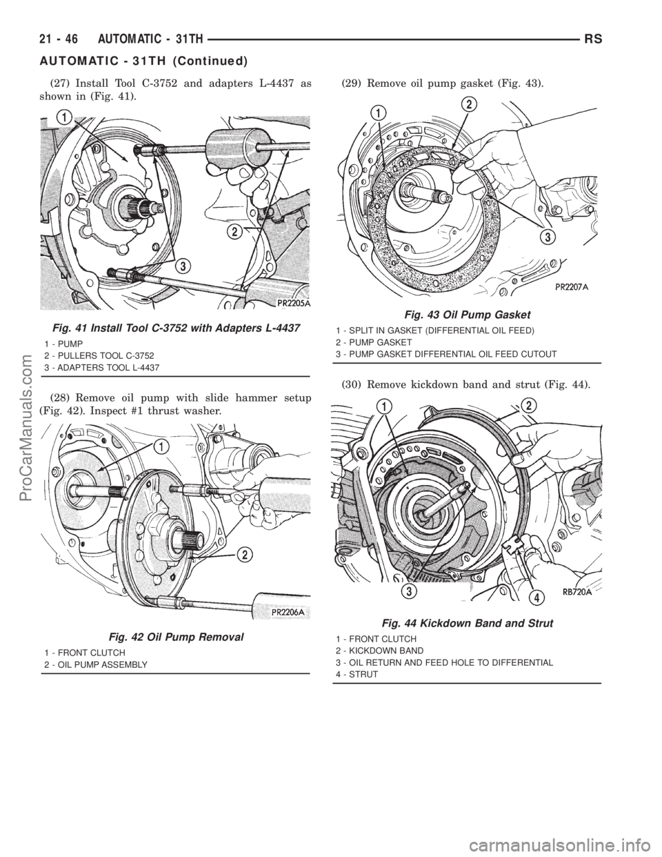
(27) Install Tool C-3752 and adapters L-4437 as
shown in (Fig. 41).
(28) Remove oil pump with slide hammer setup
(Fig. 42). Inspect #1 thrust washer.(29) Remove oil pump gasket (Fig. 43).
(30) Remove kickdown band and strut (Fig. 44).
Fig. 41 Install Tool C-3752 with Adapters L-4437
1 - PUMP
2 - PULLERS TOOL C-3752
3 - ADAPTERS TOOL L-4437
Fig. 42 Oil Pump Removal
1 - FRONT CLUTCH
2 - OIL PUMP ASSEMBLY
Fig. 43 Oil Pump Gasket
1 - SPLIT IN GASKET (DIFFERENTIAL OIL FEED)
2 - PUMP GASKET
3 - PUMP GASKET DIFFERENTIAL OIL FEED CUTOUT
Fig. 44 Kickdown Band and Strut
1 - FRONT CLUTCH
2 - KICKDOWN BAND
3 - OIL RETURN AND FEED HOLE TO DIFFERENTIAL
4 - STRUT
21 - 46 AUTOMATIC - 31THRS
AUTOMATIC - 31TH (Continued)
ProCarManuals.com
Page 1544 of 2321
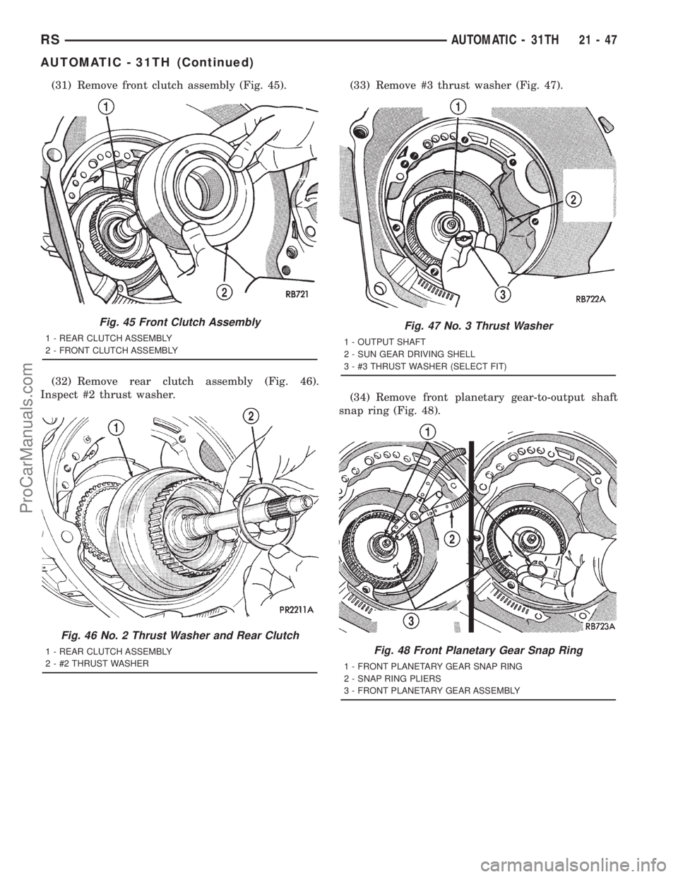
(31) Remove front clutch assembly (Fig. 45).
(32) Remove rear clutch assembly (Fig. 46).
Inspect #2 thrust washer.(33) Remove #3 thrust washer (Fig. 47).
(34) Remove front planetary gear-to-output shaft
snap ring (Fig. 48).
Fig. 45 Front Clutch Assembly
1 - REAR CLUTCH ASSEMBLY
2 - FRONT CLUTCH ASSEMBLY
Fig. 46 No. 2 Thrust Washer and Rear Clutch
1 - REAR CLUTCH ASSEMBLY
2 - #2 THRUST WASHER
Fig. 47 No. 3 Thrust Washer
1 - OUTPUT SHAFT
2 - SUN GEAR DRIVING SHELL
3 - #3 THRUST WASHER (SELECT FIT)
Fig. 48 Front Planetary Gear Snap Ring
1 - FRONT PLANETARY GEAR SNAP RING
2 - SNAP RING PLIERS
3 - FRONT PLANETARY GEAR ASSEMBLY
RSAUTOMATIC - 31TH21-47
AUTOMATIC - 31TH (Continued)
ProCarManuals.com
Page 1545 of 2321
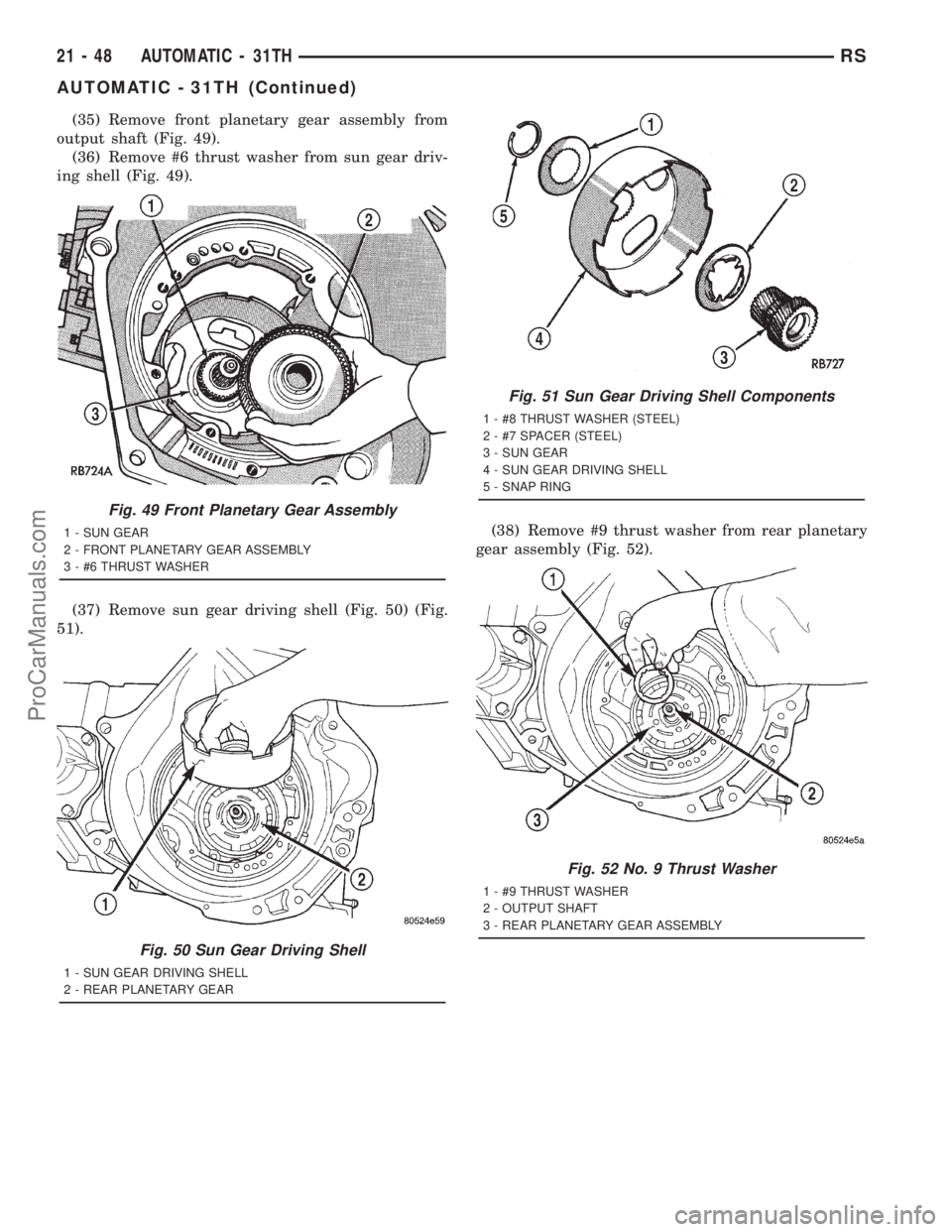
(35) Remove front planetary gear assembly from
output shaft (Fig. 49).
(36) Remove #6 thrust washer from sun gear driv-
ing shell (Fig. 49).
(37) Remove sun gear driving shell (Fig. 50) (Fig.
51).(38) Remove #9 thrust washer from rear planetary
gear assembly (Fig. 52).
Fig. 49 Front Planetary Gear Assembly
1 - SUN GEAR
2 - FRONT PLANETARY GEAR ASSEMBLY
3 - #6 THRUST WASHER
Fig. 50 Sun Gear Driving Shell
1 - SUN GEAR DRIVING SHELL
2 - REAR PLANETARY GEAR
Fig. 51 Sun Gear Driving Shell Components
1 - #8 THRUST WASHER (STEEL)
2 - #7 SPACER (STEEL)
3 - SUN GEAR
4 - SUN GEAR DRIVING SHELL
5 - SNAP RING
Fig. 52 No. 9 Thrust Washer
1 - #9 THRUST WASHER
2 - OUTPUT SHAFT
3 - REAR PLANETARY GEAR ASSEMBLY
21 - 48 AUTOMATIC - 31THRS
AUTOMATIC - 31TH (Continued)
ProCarManuals.com
Page 1546 of 2321
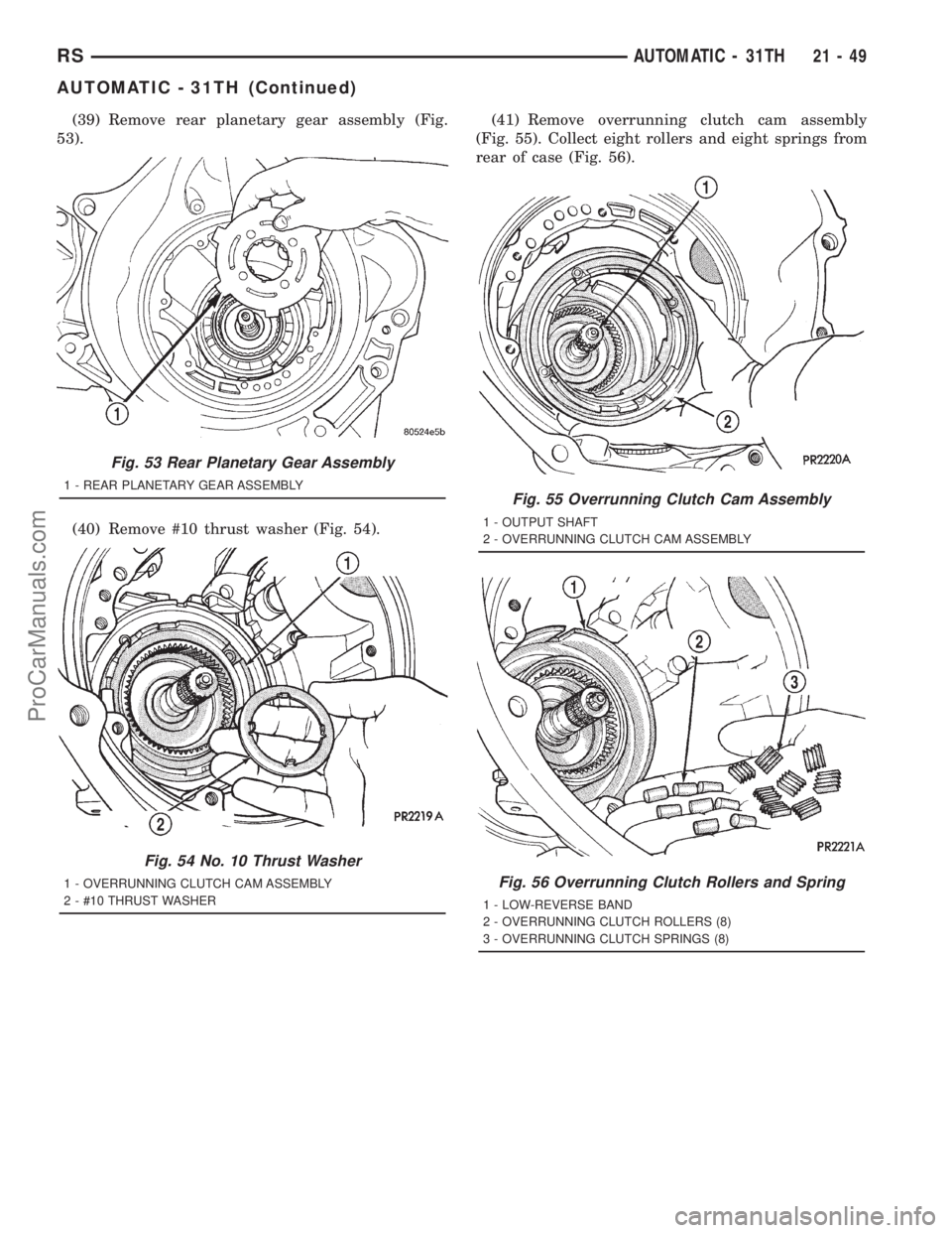
(39) Remove rear planetary gear assembly (Fig.
53).
(40) Remove #10 thrust washer (Fig. 54).(41) Remove overrunning clutch cam assembly
(Fig. 55). Collect eight rollers and eight springs from
rear of case (Fig. 56).
Fig. 53 Rear Planetary Gear Assembly
1 - REAR PLANETARY GEAR ASSEMBLY
Fig. 54 No. 10 Thrust Washer
1 - OVERRUNNING CLUTCH CAM ASSEMBLY
2 - #10 THRUST WASHER
Fig. 55 Overrunning Clutch Cam Assembly
1 - OUTPUT SHAFT
2 - OVERRUNNING CLUTCH CAM ASSEMBLY
Fig. 56 Overrunning Clutch Rollers and Spring
1 - LOW-REVERSE BAND
2 - OVERRUNNING CLUTCH ROLLERS (8)
3 - OVERRUNNING CLUTCH SPRINGS (8)
RSAUTOMATIC - 31TH21-49
AUTOMATIC - 31TH (Continued)
ProCarManuals.com
Page 1547 of 2321
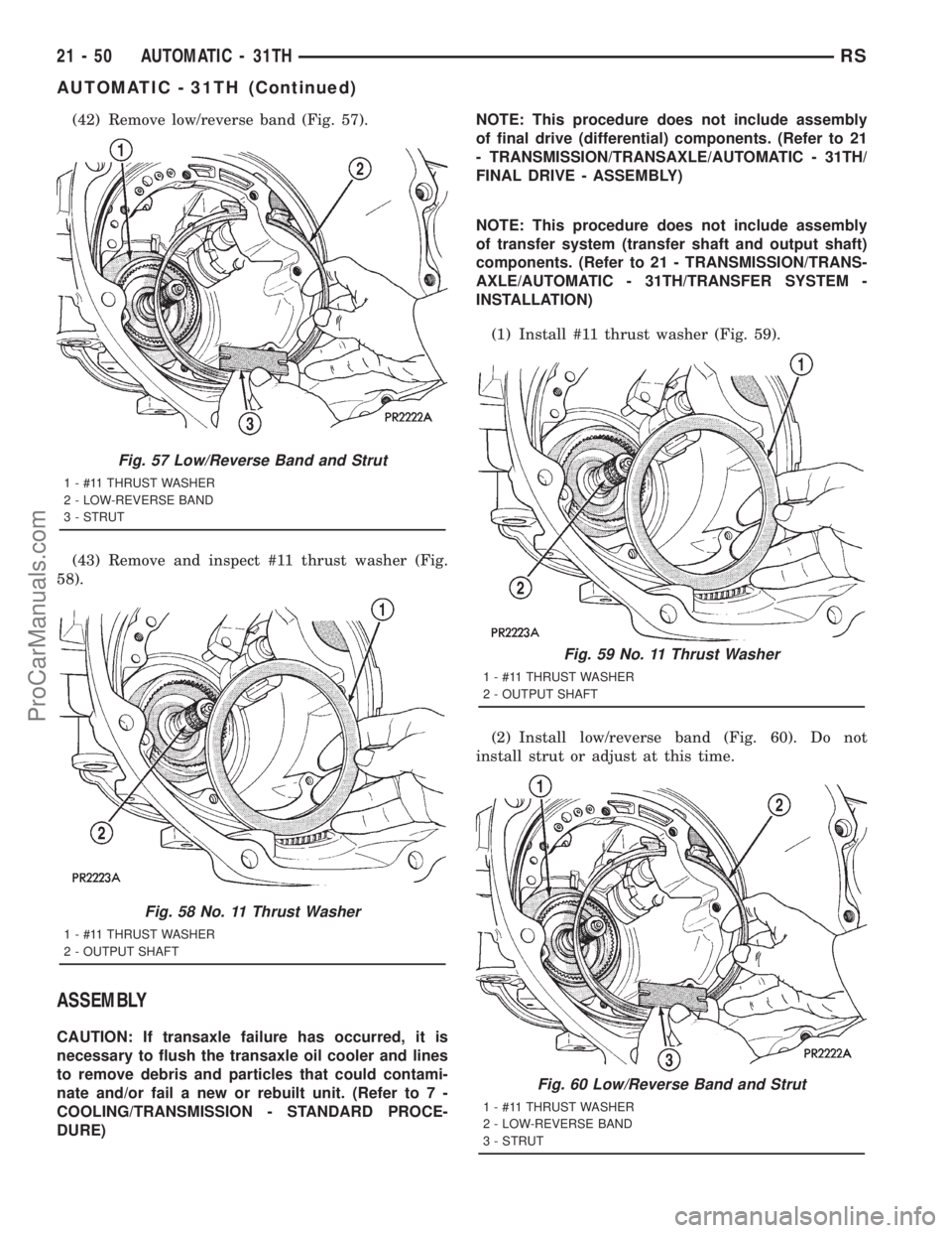
(42) Remove low/reverse band (Fig. 57).
(43) Remove and inspect #11 thrust washer (Fig.
58).
ASSEMBLY
CAUTION: If transaxle failure has occurred, it is
necessary to flush the transaxle oil cooler and lines
to remove debris and particles that could contami-
nate and/or fail a new or rebuilt unit. (Refer to 7 -
COOLING/TRANSMISSION - STANDARD PROCE-
DURE)NOTE: This procedure does not include assembly
of final drive (differential) components. (Refer to 21
- TRANSMISSION/TRANSAXLE/AUTOMATIC - 31TH/
FINAL DRIVE - ASSEMBLY)
NOTE: This procedure does not include assembly
of transfer system (transfer shaft and output shaft)
components. (Refer to 21 - TRANSMISSION/TRANS-
AXLE/AUTOMATIC - 31TH/TRANSFER SYSTEM -
INSTALLATION)
(1) Install #11 thrust washer (Fig. 59).
(2) Install low/reverse band (Fig. 60). Do not
install strut or adjust at this time.
Fig. 57 Low/Reverse Band and Strut
1 - #11 THRUST WASHER
2 - LOW-REVERSE BAND
3 - STRUT
Fig. 58 No. 11 Thrust Washer
1 - #11 THRUST WASHER
2 - OUTPUT SHAFT
Fig. 59 No. 11 Thrust Washer
1 - #11 THRUST WASHER
2 - OUTPUT SHAFT
Fig. 60 Low/Reverse Band and Strut
1 - #11 THRUST WASHER
2 - LOW-REVERSE BAND
3 - STRUT
21 - 50 AUTOMATIC - 31THRS
AUTOMATIC - 31TH (Continued)
ProCarManuals.com
Page 1548 of 2321
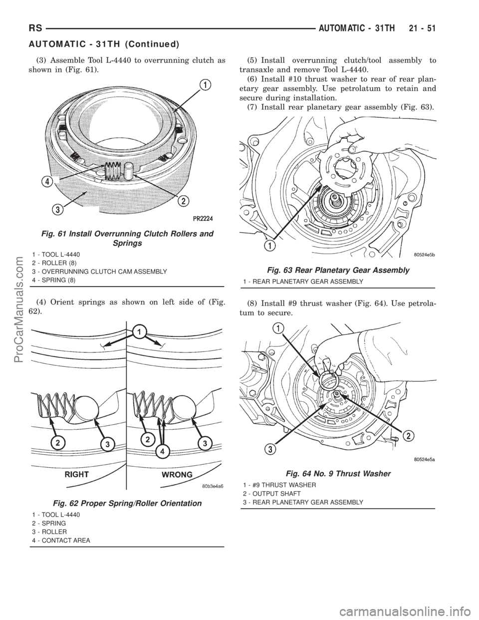
(3) Assemble Tool L-4440 to overrunning clutch as
shown in (Fig. 61).
(4) Orient springs as shown on left side of (Fig.
62).(5) Install overrunning clutch/tool assembly to
transaxle and remove Tool L-4440.
(6) Install #10 thrust washer to rear of rear plan-
etary gear assembly. Use petrolatum to retain and
secure during installation.
(7) Install rear planetary gear assembly (Fig. 63).
(8) Install #9 thrust washer (Fig. 64). Use petrola-
tum to secure.
Fig. 61 Install Overrunning Clutch Rollers and
Springs
1 - TOOL L-4440
2 - ROLLER (8)
3 - OVERRUNNING CLUTCH CAM ASSEMBLY
4 - SPRING (8)
Fig. 62 Proper Spring/Roller Orientation
1 - TOOL L-4440
2 - SPRING
3 - ROLLER
4 - CONTACT AREA
Fig. 63 Rear Planetary Gear Assembly
1 - REAR PLANETARY GEAR ASSEMBLY
Fig. 64 No. 9 Thrust Washer
1 - #9 THRUST WASHER
2 - OUTPUT SHAFT
3 - REAR PLANETARY GEAR ASSEMBLY
RSAUTOMATIC - 31TH21-51
AUTOMATIC - 31TH (Continued)
ProCarManuals.com
Page 1549 of 2321
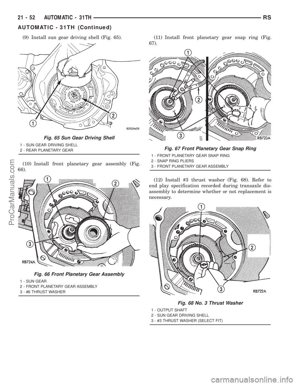
(9) Install sun gear driving shell (Fig. 65).
(10) Install front planetary gear assembly (Fig.
66).(11) Install front planetary gear snap ring (Fig.
67).
(12) Install #3 thrust washer (Fig. 68). Refer to
end play specification recorded during transaxle dis-
assembly to determine whether or not replacement is
necessary.
Fig. 65 Sun Gear Driving Shell
1 - SUN GEAR DRIVING SHELL
2 - REAR PLANETARY GEAR
Fig. 66 Front Planetary Gear Assembly
1 - SUN GEAR
2 - FRONT PLANETARY GEAR ASSEMBLY
3 - #6 THRUST WASHER
Fig. 67 Front Planetary Gear Snap Ring
1 - FRONT PLANETARY GEAR SNAP RING
2 - SNAP RING PLIERS
3 - FRONT PLANETARY GEAR ASSEMBLY
Fig. 68 No. 3 Thrust Washer
1 - OUTPUT SHAFT
2 - SUN GEAR DRIVING SHELL
3 - #3 THRUST WASHER (SELECT FIT)
21 - 52 AUTOMATIC - 31THRS
AUTOMATIC - 31TH (Continued)
ProCarManuals.com
Page 1550 of 2321
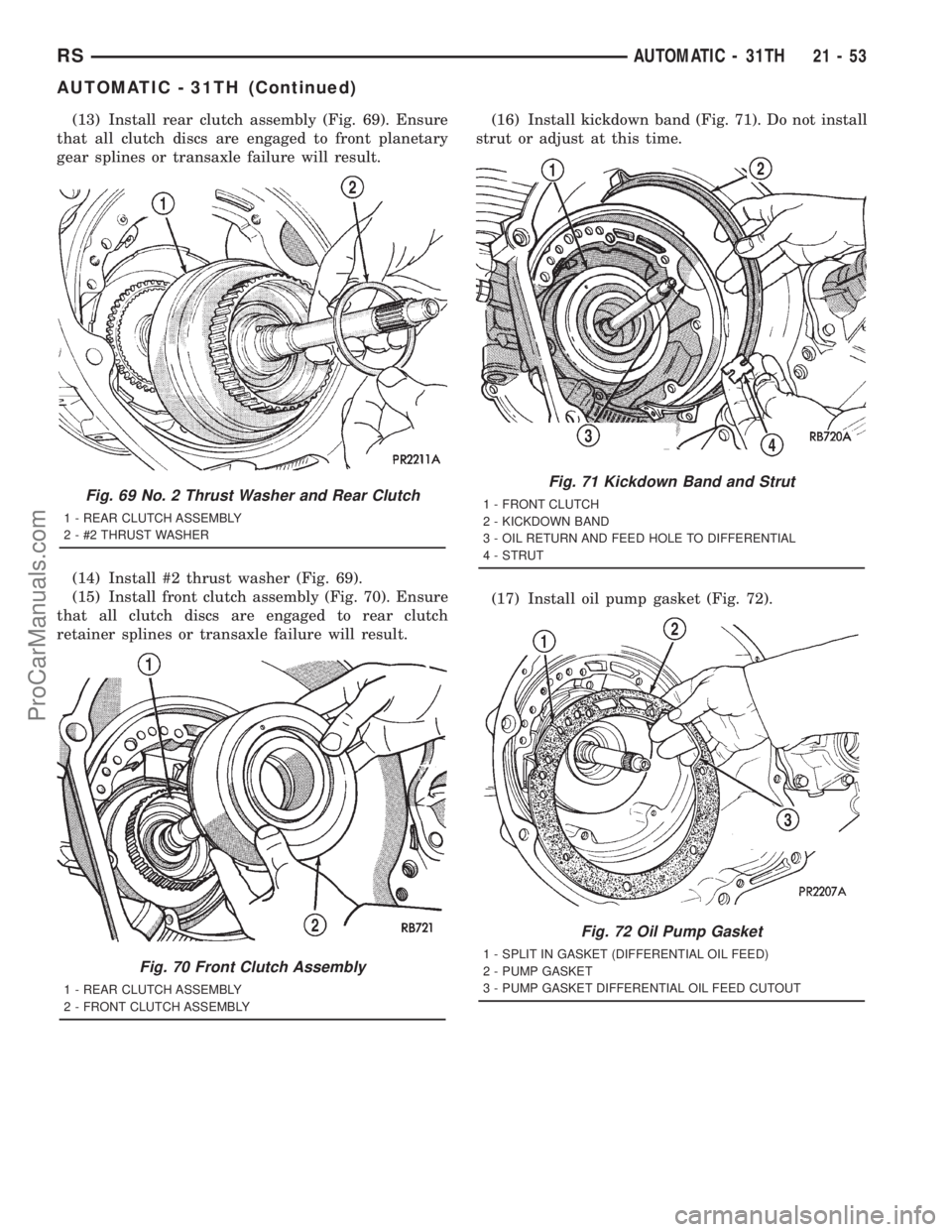
(13) Install rear clutch assembly (Fig. 69). Ensure
that all clutch discs are engaged to front planetary
gear splines or transaxle failure will result.
(14) Install #2 thrust washer (Fig. 69).
(15) Install front clutch assembly (Fig. 70). Ensure
that all clutch discs are engaged to rear clutch
retainer splines or transaxle failure will result.(16) Install kickdown band (Fig. 71). Do not install
strut or adjust at this time.
(17) Install oil pump gasket (Fig. 72).
Fig. 69 No. 2 Thrust Washer and Rear Clutch
1 - REAR CLUTCH ASSEMBLY
2 - #2 THRUST WASHER
Fig. 70 Front Clutch Assembly
1 - REAR CLUTCH ASSEMBLY
2 - FRONT CLUTCH ASSEMBLY
Fig. 71 Kickdown Band and Strut
1 - FRONT CLUTCH
2 - KICKDOWN BAND
3 - OIL RETURN AND FEED HOLE TO DIFFERENTIAL
4 - STRUT
Fig. 72 Oil Pump Gasket
1 - SPLIT IN GASKET (DIFFERENTIAL OIL FEED)
2 - PUMP GASKET
3 - PUMP GASKET DIFFERENTIAL OIL FEED CUTOUT
RSAUTOMATIC - 31TH21-53
AUTOMATIC - 31TH (Continued)
ProCarManuals.com