DODGE TOWN AND COUNTRY 2001 Service Manual
Manufacturer: DODGE, Model Year: 2001, Model line: TOWN AND COUNTRY, Model: DODGE TOWN AND COUNTRY 2001Pages: 2321, PDF Size: 68.09 MB
Page 1591 of 2321
ASSEMBLY
NOTE: The differential is serviced as an assembly.
Service is limited to bearing cups and cones. Any
other failure must be repaired by differential assem-
bly and transfer shaft replacement.
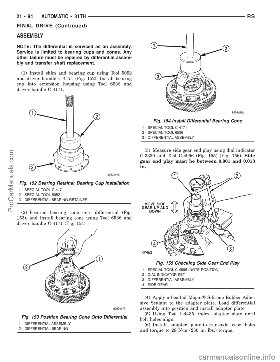
(1) Install shim and bearing cup using Tool 5052
and driver handle C-4171 (Fig. 152). Install bearing
cup into extension housing using Tool 6536 and
driver handle C-4171.
(2) Position bearing cone onto differential (Fig.
153), and install bearing cone using Tool 6536 and
driver handle C-4171 (Fig. 154).(3) Measure side gear end play using dial indicator
C-3339 and Tool C-4996 (Fig. 155) (Fig. 156).Side
gear end play must be between 0.001 and 0.013
in.
(4) Apply a bead of Moparž Silicone Rubber Adhe-
sive Sealant to the adapter plate. Load differential
assembly into position and install adapter plate .
(5) Using Tool L-4435, index adapter plate until
bolt holes align.
(6) Install adapter plate-to-transaxle case bolts
and torque to 28 N´m (250 in. lbs.) torque.
Fig. 152 Bearing Retainer Bearing Cup Installation
1 - SPECIAL TOOL C-4171
2 - SPECIAL TOOL 5052
3 - DIFFERENTIAL BEARING RETAINER
Fig. 153 Position Bearing Cone Onto Differential
1 - DIFFERENTIAL ASSEMBLY
2 - DIFFERENTIAL BEARING
Fig. 154 Install Differential Bearing Cone
1 - SPECIAL TOOL C-4171
2 - SPECIAL TOOL 6536
3 - DIFFERENTIAL ASSEMBLY
Fig. 155 Checking Side Gear End Play
1 - SPECIAL TOOL C-4996 (NOTE POSITION)
2 - DIAL INDICATOR SET
3 - DIFFERENTIAL ASSEMBLY
4 - SIDE GEAR
21 - 94 AUTOMATIC - 31THRS
FINAL DRIVE (Continued)
ProCarManuals.com
Page 1592 of 2321
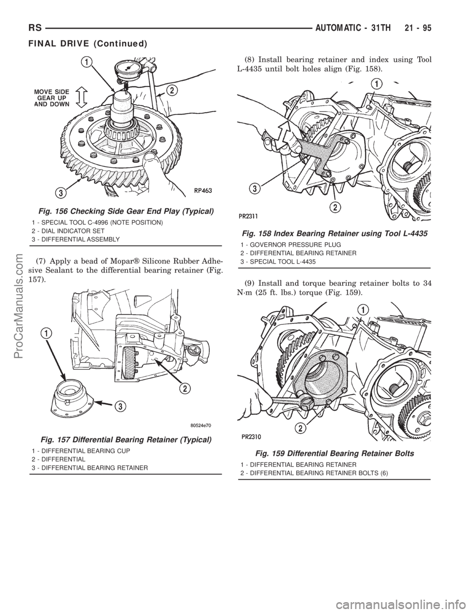
(7) Apply a bead of Moparž Silicone Rubber Adhe-
sive Sealant to the differential bearing retainer (Fig.
157).(8) Install bearing retainer and index using Tool
L-4435 until bolt holes align (Fig. 158).
(9) Install and torque bearing retainer bolts to 34
N´m (25 ft. lbs.) torque (Fig. 159).
Fig. 156 Checking Side Gear End Play (Typical)
1 - SPECIAL TOOL C-4996 (NOTE POSITION)
2 - DIAL INDICATOR SET
3 - DIFFERENTIAL ASSEMBLY
Fig. 157 Differential Bearing Retainer (Typical)
1 - DIFFERENTIAL BEARING CUP
2 - DIFFERENTIAL
3 - DIFFERENTIAL BEARING RETAINER
Fig. 158 Index Bearing Retainer using Tool L-4435
1 - GOVERNOR PRESSURE PLUG
2 - DIFFERENTIAL BEARING RETAINER
3 - SPECIAL TOOL L-4435
Fig. 159 Differential Bearing Retainer Bolts
1 - DIFFERENTIAL BEARING RETAINER
2 - DIFFERENTIAL BEARING RETAINER BOLTS (6)
RSAUTOMATIC - 31TH21-95
FINAL DRIVE (Continued)
ProCarManuals.com
Page 1593 of 2321
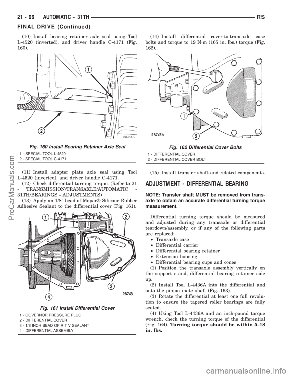
(10) Install bearing retainer axle seal using Tool
L-4520 (inverted), and driver handle C-4171 (Fig.
160).
(11) Install adapter plate axle seal using Tool
L-4520 (inverted), and driver handle C-4171.
(12) Check differential turning torque. (Refer to 21
- TRANSMISSION/TRANSAXLE/AUTOMATIC -
31TH/BEARINGS - ADJUSTMENTS)
(13) Apply an 1/8º bead of Moparž Silicone Rubber
Adhesive Sealant to the differential cover (Fig. 161).(14) Install differential cover-to-transaxle case
bolts and torque to 19 N´m (165 in. lbs.) torque (Fig.
162).
(15) Install transfer shaft and related components.
ADJUSTMENT - DIFFERENTIAL BEARING
NOTE: Transfer shaft MUST be removed from trans-
axle to obtain an accurate differential turning torque
measurement.
Differential turning torque should be measured
and adjusted during any transaxle or differential
teardown/assembly, or if any of the following parts
are replaced:
²Transaxle case
²Differential carrier
²Differential bearing retainer
²Extension housing
²Differential bearing cups and cones
(1) Position the transaxle assembly vertically on
the support stand, differential bearing retainer side
up.
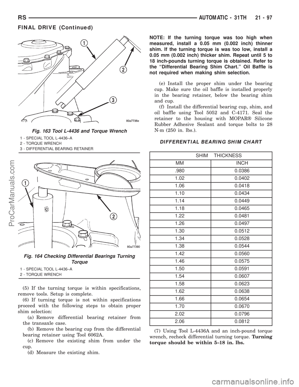
(2) Install Tool L-4436A into the differential and
onto the pinion mate shaft (Fig. 163).
(3) Rotate the differential at least one full revolu-
tion to ensure the tapered roller bearings are fully
seated.
(4) Using Tool L-4436A and an inch-pound torque
wrench, check the turning torque of the differential
(Fig. 164).Turning torque should be within 5±18
in. lbs.
Fig. 160 Install Bearing Retainer Axle Seal
1 - SPECIAL TOOL L-4520
2 - SPECIAL TOOL C-4171
Fig. 161 Install Differential Cover
1 - GOVERNOR PRESSURE PLUG
2 - DIFFERENTIAL COVER
3 - 1/8 INCH BEAD OF R T V SEALANT
4 - DIFFERENTIAL ASSEMBLY
Fig. 162 Differential Cover Bolts
1 - DIFFERENTIAL COVER
2 - DIFFERENTIAL COVER BOLT
21 - 96 AUTOMATIC - 31THRS
FINAL DRIVE (Continued)
ProCarManuals.com
Page 1594 of 2321
(5) If the turning torque is within specifications,
remove tools. Setup is complete.
(6) If turning torque is not within specifications
proceed with the following steps to obtain proper
shim selection:
(a) Remove differential bearing retainer from
the transaxle case.
(b) Remove the bearing cup from the differential
bearing retainer using Tool 6062A.
(c) Remove the existing shim from under the
cup.
(d) Measure the existing shim.NOTE: If the turning torque was too high when
measured, install a 0.05 mm (0.002 inch) thinner
shim. If the turning torque is was too low, install a
0.05 mm (0.002 inch) thicker shim. Repeat until 5 to
18 inch-pounds turning torque is obtained. Refer to
the ªDifferential Bearing Shim Chart.º Oil Baffle is
not required when making shim selection.
(e) Install the proper shim under the bearing
cup. Make sure the oil baffle is installed properly
in the bearing retainer, below the bearing shim
and cup.
(f) Install the differential bearing cup, shim, and
oil baffle using Tool 5052 and C-4171. Seal the
retainer to the housing with MOPARž Silicone
Rubber Adhesive Sealant and torque bolts to 28
N´m (250 in. lbs.).
DIFFERENTIAL BEARING SHIM CHART
SHIM THICKNESS
MM INCH
.980 0.0386
1.02 0.0402
1.06 0.0418
1.10 0.0434
1.14 0.0449
1.18 0.0465
1.22 0.0481
1.26 0.0497
1.30 0.0512
1.34 0.0528
1.38 0.0544
1.42 0.0560
1.46 0.0575
1.50 0.0591
1.54 0.0607
1.58 0.0623
1.62 0.0638
1.66 0.0654
1.70 0.0670
2.02 0.0796
2.06 0.0812
(7) Using Tool L-4436A and an inch-pound torque
wrench, recheck differential turning torque.Turning
torque should be within 5±18 in. lbs.
Fig. 163 Tool L-4436 and Torque Wrench
1 - SPECIAL TOOL L-4436±A
2 - TORQUE WRENCH
3 - DIFFERENTIAL BEARING RETAINER
Fig. 164 Checking Differential Bearings Turning
Torque
1 - SPECIAL TOOL L-4436±A
2 - TORQUE WRENCH
RSAUTOMATIC - 31TH21-97
FINAL DRIVE (Continued)
ProCarManuals.com
Page 1595 of 2321
FLUID
STANDARD PROCEDURE - FLUID LEVEL AND
CONDITION CHECK
NOTE: The transmission and differential sump have
a common oil sump with a communicating opening
between the two.
FLUID LEVEL CHECK
The torque converter fills in both the P Park and N
Neutral positions. Place the selector lever in P Park
to be sure that the fluid level check is accurate.The
engine should be running at idle speed for at
least one minute, with the vehicle on level
ground. This will assure complete oil level sta-
bilization between differential and transmis-
sion.The fluid should be at normal operating
temperature (approximately 82 C. or 180 F.). The
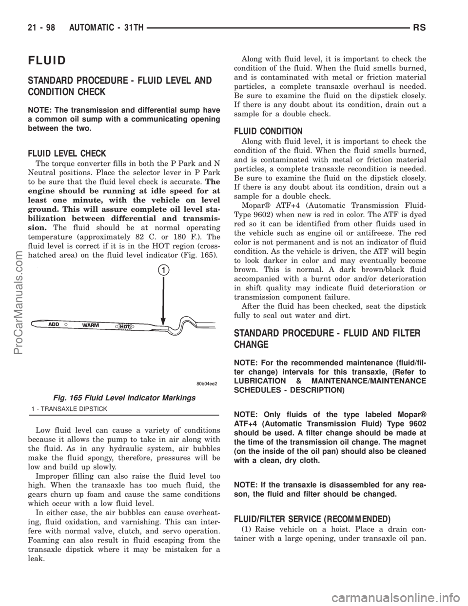
fluid level is correct if it is in the HOT region (cross-
hatched area) on the fluid level indicator (Fig. 165).
Low fluid level can cause a variety of conditions
because it allows the pump to take in air along with
the fluid. As in any hydraulic system, air bubbles
make the fluid spongy, therefore, pressures will be
low and build up slowly.
Improper filling can also raise the fluid level too
high. When the transaxle has too much fluid, the
gears churn up foam and cause the same conditions
which occur with a low fluid level.
In either case, the air bubbles can cause overheat-
ing, fluid oxidation, and varnishing. This can inter-
fere with normal valve, clutch, and servo operation.
Foaming can also result in fluid escaping from the
transaxle dipstick where it may be mistaken for a
leak.Along with fluid level, it is important to check the
condition of the fluid. When the fluid smells burned,
and is contaminated with metal or friction material
particles, a complete transaxle overhaul is needed.
Be sure to examine the fluid on the dipstick closely.
If there is any doubt about its condition, drain out a
sample for a double check.
FLUID CONDITION
Along with fluid level, it is important to check the
condition of the fluid. When the fluid smells burned,
and is contaminated with metal or friction material
particles, a complete transaxle recondition is needed.
Be sure to examine the fluid on the dipstick closely.
If there is any doubt about its condition, drain out a
sample for a double check.
Moparž ATF+4 (Automatic Transmission Fluid-
Type 9602) when new is red in color. The ATF is dyed
red so it can be identified from other fluids used in
the vehicle such as engine oil or antifreeze. The red
color is not permanent and is not an indicator of fluid
condition. As the vehicle is driven, the ATF will begin
to look darker in color and may eventually become
brown. This is normal. A dark brown/black fluid
accompanied with a burnt odor and/or deterioration
in shift quality may indicate fluid deterioration or
transmission component failure.
After the fluid has been checked, seat the dipstick
fully to seal out water and dirt.
STANDARD PROCEDURE - FLUID AND FILTER
CHANGE
NOTE: For the recommended maintenance (fluid/fil-
ter change) intervals for this transaxle, (Refer to
LUBRICATION & MAINTENANCE/MAINTENANCE
SCHEDULES - DESCRIPTION)
NOTE: Only fluids of the type labeled Moparž
ATF+4 (Automatic Transmission Fluid) Type 9602
should be used. A filter change should be made at
the time of the transmission oil change. The magnet
(on the inside of the oil pan) should also be cleaned
with a clean, dry cloth.
NOTE: If the transaxle is disassembled for any rea-
son, the fluid and filter should be changed.
FLUID/FILTER SERVICE (RECOMMENDED)
(1) Raise vehicle on a hoist. Place a drain con-
tainer with a large opening, under transaxle oil pan.
Fig. 165 Fluid Level Indicator Markings
1 - TRANSAXLE DIPSTICK
21 - 98 AUTOMATIC - 31THRS
ProCarManuals.com
Page 1596 of 2321
(2) Loosen pan bolts and tap the pan at one corner
to break it loose allowing fluid to drain, then remove
the oil pan.
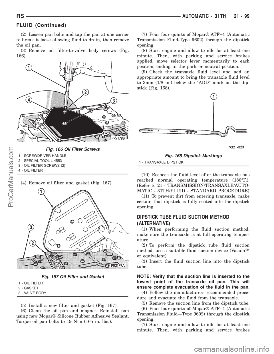
(3) Remove oil filter-to-valve body screws (Fig.
166).
(4) Remove oil filter and gasket (Fig. 167).
(5) Install a new filter and gasket (Fig. 167).
(6) Clean the oil pan and magnet. Reinstall pan
using new Moparž Silicone Rubber Adhesive Sealant.
Torque oil pan bolts to 19 N´m (165 in. lbs.).(7) Pour four quarts of Moparž ATF+4 (Automatic
Transmission Fluid-Type 9602) through the dipstick
opening.
(8) Start engine and allow to idle for at least one
minute. Then, with parking and service brakes
applied, move selector lever momentarily to each
position, ending in the park or neutral position.
(9) Check the transaxle fluid level and add an
appropriate amount to bring the transaxle fluid level
to 3mm (1/8 in.) below the ªADDº mark on the dip-
stick (Fig. 168).
(10) Recheck the fluid level after the transaxle has
reached normal operating temperature (180ÉF.).
(Refer to 21 - TRANSMISSION/TRANSAXLE/AUTO-
MATIC - 31TH/FLUID - STANDARD PROCEDURE)
(11) To prevent dirt from entering transaxle, make
certain that dipstick is fully seated into the dipstick
opening.
DIPSTICK TUBE FLUID SUCTION METHOD
(ALTERNATIVE)
(1) When performing the fluid suction method,
make sure the transaxle is at full operating temper-
ature.
(2) To perform the dipstick tube fluid suction
method, use a suitable fluid suction device (VaculaŸ
or equivalent).
(3) Insert the fluid suction line into the dipstick
tube.
NOTE: Verify that the suction line is inserted to the
lowest point of the transaxle oil pan. This will
ensure complete evacuation of the fluid in the pan.
(4) Follow the manufacturers recommended proce-
dure and evacuate the fluid from the transaxle.
(5) Remove the suction line from the dipstick tube.
(6) Pour four quarts of Moparž ATF+4 (Automatic
Transmission FluidÐType 9602) through the dipstick
opening.
(7) Start engine and allow to idle for at least one
minute. Then, with parking and service brakes
Fig. 166 Oil Filter Screws
1 - SCREWDRIVER HANDLE
2 - SPECIAL TOOL L-4553
3 - OIL FILTER SCREWS (2)
4 - OIL FILTER
Fig. 167 Oil Filter and Gasket
1 - OIL FILTER
2 - GASKET
3 - VALVE BODY
Fig. 168 Dipstick Markings
1 - TRANSAXLE DIPSTICK
RSAUTOMATIC - 31TH21-99
FLUID (Continued)
ProCarManuals.com
Page 1597 of 2321
applied, move selector lever momentarily to each
position, ending in the park or neutral position.
(8) Check the transaxle fluid level and add an
appropriate amount to bring the transaxle fluid level
to 3mm (1/8 in.) below the ªADDº mark on the dip-
stick (Fig. 168).
(9) Recheck the fluid level after the transaxle has
reached normal operating temperature (180ÉF.).
(Refer to 21 - TRANSMISSION/TRANSAXLE/AUTO-
MATIC - 31TH/FLUID - STANDARD PROCEDURE)
(10) To prevent dirt from entering transaxle, make
certain that dipstick is fully seated into the dipstick
opening.
GEAR SHIFT CABLE
REMOVAL
(1) Disconnect battery negative cable.
(2) Disconnect gear shift cable at manual valve
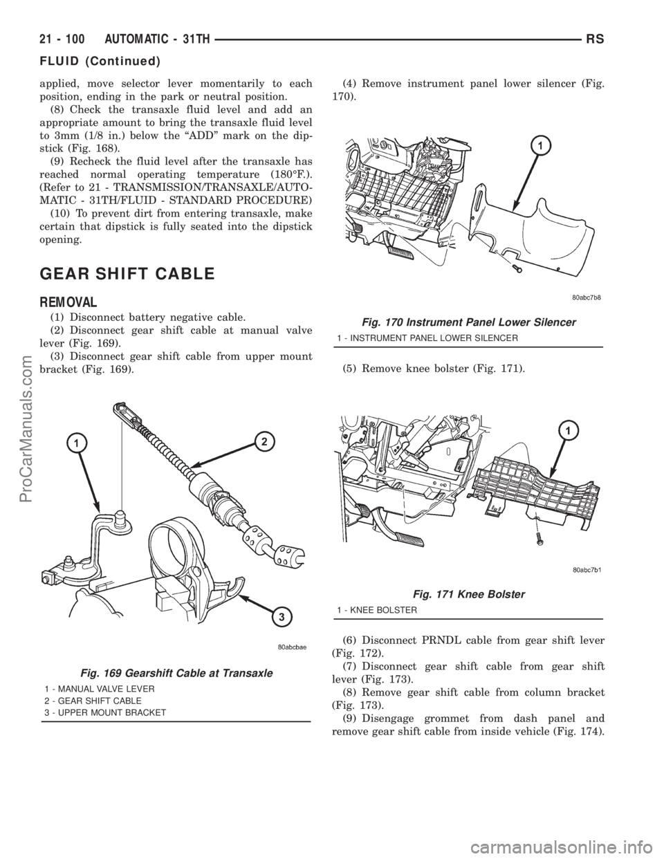
lever (Fig. 169).
(3) Disconnect gear shift cable from upper mount
bracket (Fig. 169).(4) Remove instrument panel lower silencer (Fig.
170).
(5) Remove knee bolster (Fig. 171).
(6) Disconnect PRNDL cable from gear shift lever
(Fig. 172).
(7) Disconnect gear shift cable from gear shift
lever (Fig. 173).
(8) Remove gear shift cable from column bracket
(Fig. 173).
(9) Disengage grommet from dash panel and
remove gear shift cable from inside vehicle (Fig. 174).
Fig. 169 Gearshift Cable at Transaxle
1 - MANUAL VALVE LEVER
2 - GEAR SHIFT CABLE
3 - UPPER MOUNT BRACKET
Fig. 170 Instrument Panel Lower Silencer
1 - INSTRUMENT PANEL LOWER SILENCER
Fig. 171 Knee Bolster
1 - KNEE BOLSTER
21 - 100 AUTOMATIC - 31THRS
FLUID (Continued)
ProCarManuals.com
Page 1598 of 2321
INSTALLATION
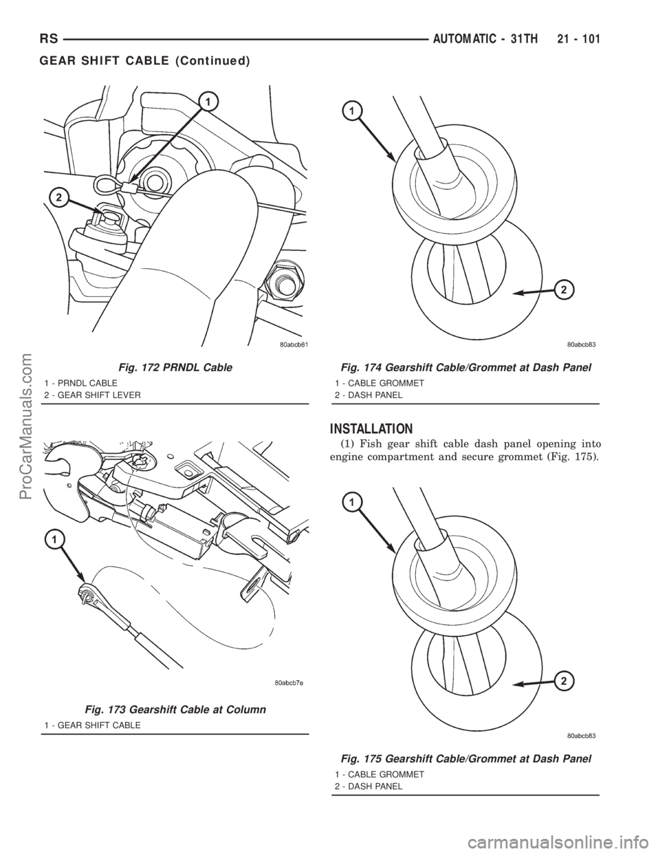
(1) Fish gear shift cable dash panel opening into
engine compartment and secure grommet (Fig. 175).
Fig. 172 PRNDL Cable
1 - PRNDL CABLE
2 - GEAR SHIFT LEVER
Fig. 173 Gearshift Cable at Column
1 - GEAR SHIFT CABLE
Fig. 174 Gearshift Cable/Grommet at Dash Panel
1 - CABLE GROMMET
2 - DASH PANEL
Fig. 175 Gearshift Cable/Grommet at Dash Panel
1 - CABLE GROMMET
2 - DASH PANEL
RSAUTOMATIC - 31TH21 - 101
GEAR SHIFT CABLE (Continued)
ProCarManuals.com
Page 1599 of 2321
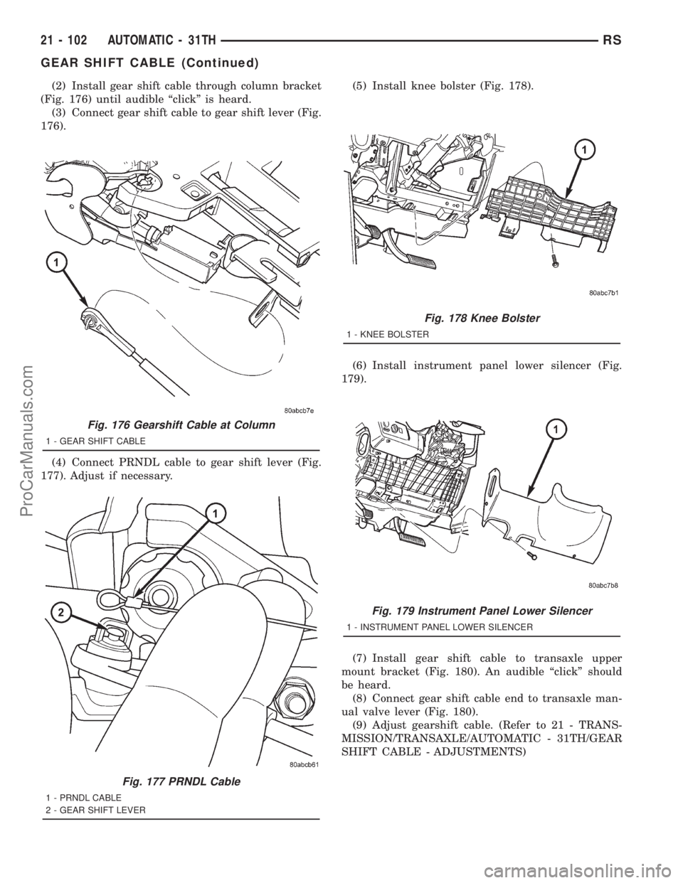
(2) Install gear shift cable through column bracket
(Fig. 176) until audible ªclickº is heard.
(3) Connect gear shift cable to gear shift lever (Fig.
176).
(4) Connect PRNDL cable to gear shift lever (Fig.
177). Adjust if necessary.(5) Install knee bolster (Fig. 178).
(6) Install instrument panel lower silencer (Fig.
179).
(7) Install gear shift cable to transaxle upper
mount bracket (Fig. 180). An audible ªclickº should
be heard.
(8) Connect gear shift cable end to transaxle man-
ual valve lever (Fig. 180).
(9) Adjust gearshift cable. (Refer to 21 - TRANS-
MISSION/TRANSAXLE/AUTOMATIC - 31TH/GEAR
SHIFT CABLE - ADJUSTMENTS)
Fig. 176 Gearshift Cable at Column
1 - GEAR SHIFT CABLE
Fig. 177 PRNDL Cable
1 - PRNDL CABLE
2 - GEAR SHIFT LEVER
Fig. 178 Knee Bolster
1 - KNEE BOLSTER
Fig. 179 Instrument Panel Lower Silencer
1 - INSTRUMENT PANEL LOWER SILENCER
21 - 102 AUTOMATIC - 31THRS
GEAR SHIFT CABLE (Continued)
ProCarManuals.com
Page 1600 of 2321
GEARSHIFT CABLE ADJUSTMENT
Lift and rotate the gearshift hand lever into the
park (P) gate position and remove the ignition key.
This confirms the shift lever is in the gated park (P)
position.
After confirming the park gate position, turn the
ignition switch . If the starter will operate, the park
gate position is correct. Move the shift lever into the
neutral (N) position. If the starter will operate in this
position, the linkage is properly adjusted. If the
starter fails to operate in either position, linkage
adjustment is required.
(1) Park the vehicle on level ground and set the
parking brake.
(2) Place the gearshift lever in park (P) gate posi-
tion and remove key.
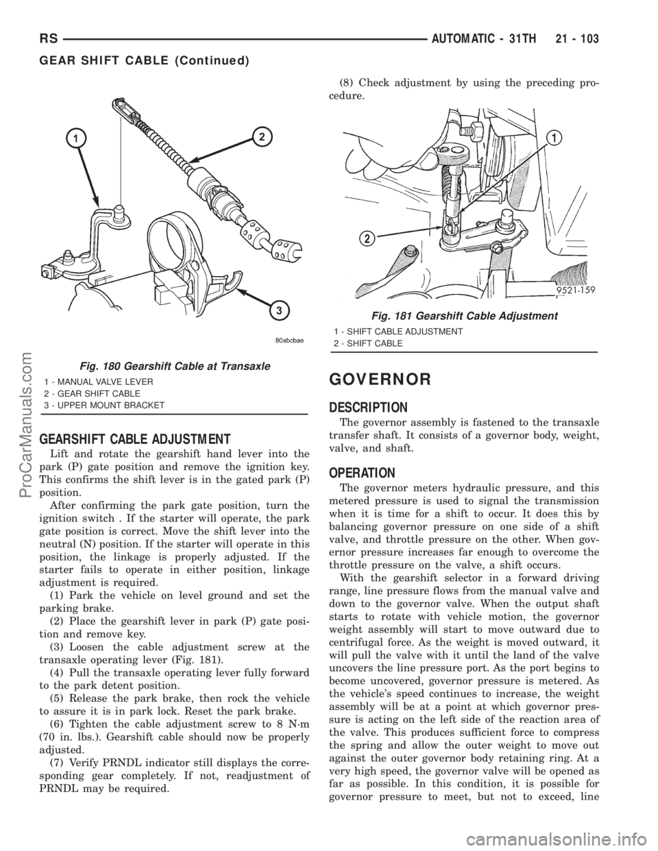
(3) Loosen the cable adjustment screw at the
transaxle operating lever (Fig. 181).
(4) Pull the transaxle operating lever fully forward
to the park detent position.
(5) Release the park brake, then rock the vehicle
to assure it is in park lock. Reset the park brake.
(6) Tighten the cable adjustment screw to 8 N´m
(70 in. lbs.). Gearshift cable should now be properly
adjusted.
(7) Verify PRNDL indicator still displays the corre-
sponding gear completely. If not, readjustment of
PRNDL may be required.(8) Check adjustment by using the preceding pro-
cedure.
GOVERNOR
DESCRIPTION
The governor assembly is fastened to the transaxle
transfer shaft. It consists of a governor body, weight,
valve, and shaft.
OPERATION
The governor meters hydraulic pressure, and this
metered pressure is used to signal the transmission
when it is time for a shift to occur. It does this by
balancing governor pressure on one side of a shift
valve, and throttle pressure on the other. When gov-
ernor pressure increases far enough to overcome the
throttle pressure on the valve, a shift occurs.
With the gearshift selector in a forward driving
range, line pressure flows from the manual valve and
down to the governor valve. When the output shaft
starts to rotate with vehicle motion, the governor
weight assembly will start to move outward due to
centrifugal force. As the weight is moved outward, it
will pull the valve with it until the land of the valve
uncovers the line pressure port. As the port begins to
become uncovered, governor pressure is metered. As
the vehicle's speed continues to increase, the weight
assembly will be at a point at which governor pres-
sure is acting on the left side of the reaction area of
the valve. This produces sufficient force to compress
the spring and allow the outer weight to move out
against the outer governor body retaining ring. At a
very high speed, the governor valve will be opened as
far as possible. In this condition, it is possible for
governor pressure to meet, but not to exceed, line
Fig. 180 Gearshift Cable at Transaxle
1 - MANUAL VALVE LEVER
2 - GEAR SHIFT CABLE
3 - UPPER MOUNT BRACKET
Fig. 181 Gearshift Cable Adjustment
1 - SHIFT CABLE ADJUSTMENT
2 - SHIFT CABLE
RSAUTOMATIC - 31TH21 - 103
GEAR SHIFT CABLE (Continued)
ProCarManuals.com