DODGE TOWN AND COUNTRY 2001 Service Manual
Manufacturer: DODGE, Model Year: 2001, Model line: TOWN AND COUNTRY, Model: DODGE TOWN AND COUNTRY 2001Pages: 2321, PDF Size: 68.09 MB
Page 161 of 2321
JUNCTION BLOCK
DESCRIPTION...........................32
OPERATION.............................32
REMOVAL..............................32
INSTALLATION...........................33
MASTER CYLINDER
DESCRIPTION...........................33
OPERATION.............................34
STANDARD PROCEDURE..................34
MASTER CYLINDER BLEEDING...........34
REMOVAL..............................34
DISASSEMBLY...........................35
ASSEMBLY.............................36
INSTALLATION...........................36
POWER BRAKE BOOSTER
DESCRIPTION...........................37
OPERATION.............................37
DIAGNOSIS AND TESTING.................38
POWER BRAKE BOOSTER...............38
REMOVAL..............................38
INSTALLATION...........................40
PROPORTIONING VALVE
DESCRIPTION...........................41
OPERATION.............................42
DIAGNOSIS AND TESTING.................42
PROPORTIONING VALVE (HEIGHT
SENSING).............................42
REMOVAL..............................43
INSTALLATION...........................43
ROTORS
DIAGNOSIS AND TESTING.................44BRAKE ROTOR........................44
STANDARD PROCEDURE..................47
BRAKE ROTOR MACHINING..............47
REMOVAL..............................48
INSTALLATION...........................48
SUPPORT PLATE - DRUM BRAKE
REMOVAL..............................48
INSTALLATION...........................49
WHEEL CYLINDERS
REMOVAL..............................50
INSPECTION............................50
INSTALLATION...........................50
PARKING BRAKE
DESCRIPTION...........................50
OPERATION.............................51
STANDARD PROCEDURE..................51
PARKING BRAKE AUTOMATIC ADJUSTER
MECHANISM RELEASE..................51
PARKING BRAKE AUTOMATIC ADJUSTER
RESET...............................51
LEVER - PARKING BRAKE
REMOVAL..............................52
INSTALLATION...........................53
SHOES - PARKING BRAKE
REMOVAL..............................53
INSTALLATION...........................58
ADJUSTMENTS..........................59
CABLES - PARKING BRAKE
REMOVAL..............................61
INSTALLATION...........................65
ADJUSTMENTS..........................66
BRAKES - BASE
DESCRIPTION - BASE BRAKES
The base brake system consists of the following
components:
²Brake pedal
²Power brake booster
²Master cylinder
²Brake tubes and hoses
²Proportioning valve (non-ABS vehicles only)
²Disc brakes
²Drum brakes
²Brake lamp switch
²Brake fluid level switch
²Parking brakes
Front disc brakes control the braking of the front
wheels; rear braking is controlled by rear drum
brakes or rear disc brakes depending on options.
The hydraulic brake system is diagonally split on
both the non-antilock braking systems and antilock
braking systems. That means the left front and right
rear brakes are on one hydraulic circuit and the right
front and left rear are on the other.For information on the brake lamp switch, (Refer
to 8 - ELECTRICAL/LAMPS/LIGHTING - EXTERI-
OR/BRAKE LAMP SWITCH - DESCRIPTION)
Vehicles equipped with the optional antilock brake
system (ABS) use a system designated Mark 20e. It
is available with or without traction control. This
system shares most base brake hardware used on
vehicles without ABS. ABS components are described
in detail in ANTILOCK BRAKE SYSTEM.
OPERATION - BASE BRAKES
When a vehicle needs to be stopped, the driver
applies the brake pedal. The brake pedal pushes the
input rod of the power brake booster into the booster.
The booster uses vacuum to ease pedal effort as force
is transferred through the booster to the master cyl-
inder. The booster's output rod pushes in the master
cylinder's primary and secondary pistons applying
hydraulic pressure through the chassis brake tubes
to the brakes at each tire and wheel assembly.
The parking brakes are foot-operated. When
applied, the parking brake lever pulls on cables that
actuate brake shoes at each rear wheel. These shoes
come in contact with a hub mounted drum (drum for
5 - 2 BRAKES - BASERS
ProCarManuals.com
Page 162 of 2321
disc/drum brakes or drum-in-hat for disc/disc brakes)
and hold it in place.
WARNING: DUST AND DIRT ACCUMULATING ON
BRAKE PARTS DURING NORMAL USE MAY CON-
TAIN ASBESTOS FIBERS FROM PRODUCTION OR
AFTERMARKET BRAKE LININGS. BREATHING
EXCESSIVE CONCENTRATIONS OF ASBESTOS
FIBERS CAN CAUSE SERIOUS BODILY HARM.
EXERCISE CARE WHEN SERVICING BRAKE
PARTS. DO NOT SAND OR GRIND BRAKE LINING
UNLESS EQUIPMENT USED IS DESIGNED TO CON-
TAIN THE DUST RESIDUE. DO NOT CLEAN BRAKE
PARTS WITH COMPRESSED AIR OR BY DRY
BRUSHING. CLEANING SHOULD BE DONE BY
DAMPENING THE BRAKE COMPONENTS WITH A
FINE MIST OF WATER, THEN WIPING THE BRAKE
COMPONENTS CLEAN WITH A DAMPENED CLOTH.
DISPOSE OF CLOTH AND ALL RESIDUE CONTAIN-
ING ASBESTOS FIBERS IN AN IMPERMEABLE
CONTAINER WITH THE APPROPRIATE LABEL. FOL-
LOW PRACTICES PRESCRIBED BY THE OCCUPA-
TIONAL SAFETY AND HEALTH ADMINISTRATION
(OSHA) AND THE ENVIRONMENTAL PROTECTION
AGENCY (EPA) FOR THE HANDLING, PROCESSING,
AND DISPOSING OF DUST OR DEBRIS THAT MAY
CONTAIN ASBESTOS FIBERS.
CAUTION: During service procedures, grease or
any other foreign material must be kept off brake
shoe assemblies, and braking surfaces of brake
rotor or drum, and external surfaces of hub and
bearing assembly.
CAUTION: Handling of brake rotors and calipers
must be done in such a way as to avoid damage to
the rotor and scratching or nicking of brake lining
on the brake shoes.
CAUTION: At no time when servicing a vehicle, can
a sheet metal screw, bolt or other metal fastener be
installed in the shock tower to take the place of an
original plastic clip. Also, NO holes can be drilled
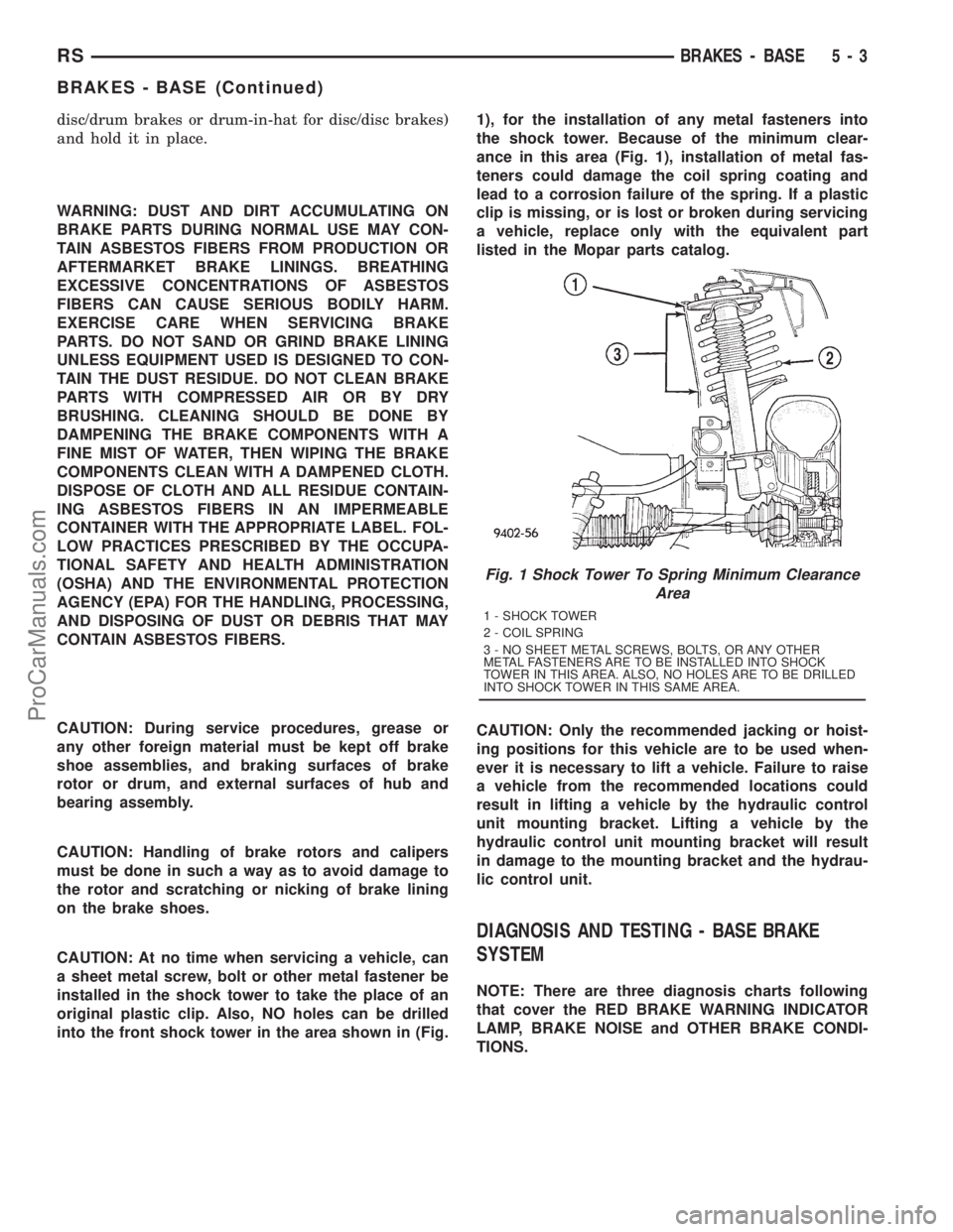
into the front shock tower in the area shown in (Fig.1), for the installation of any metal fasteners into
the shock tower. Because of the minimum clear-
ance in this area (Fig. 1), installation of metal fas-
teners could damage the coil spring coating and
lead to a corrosion failure of the spring. If a plastic
clip is missing, or is lost or broken during servicing
a vehicle, replace only with the equivalent part
listed in the Mopar parts catalog.
CAUTION: Only the recommended jacking or hoist-
ing positions for this vehicle are to be used when-
ever it is necessary to lift a vehicle. Failure to raise
a vehicle from the recommended locations could
result in lifting a vehicle by the hydraulic control
unit mounting bracket. Lifting a vehicle by the
hydraulic control unit mounting bracket will result
in damage to the mounting bracket and the hydrau-
lic control unit.
DIAGNOSIS AND TESTING - BASE BRAKE
SYSTEM
NOTE: There are three diagnosis charts following
that cover the RED BRAKE WARNING INDICATOR
LAMP, BRAKE NOISE and OTHER BRAKE CONDI-
TIONS.
Fig. 1 Shock Tower To Spring Minimum Clearance
Area
1 - SHOCK TOWER
2 - COIL SPRING
3 - NO SHEET METAL SCREWS, BOLTS, OR ANY OTHER
METAL FASTENERS ARE TO BE INSTALLED INTO SHOCK
TOWER IN THIS AREA. ALSO, NO HOLES ARE TO BE DRILLED
INTO SHOCK TOWER IN THIS SAME AREA.
RSBRAKES - BASE5-3
BRAKES - BASE (Continued)
ProCarManuals.com
Page 163 of 2321
RED BRAKE WARNING INDICATOR LAMP
CONDITION POSSIBLE CAUSES CORRECTION
RED BRAKE WARNING
LAMP ON1. Parking brake lever not fully
released.1. Release parking brake lever.
2. Parking brake warning lamp
switch on parking brake lever.2. Inspect and replace switch as necessary.
3. Brake fluid level low in reservoir. 3. Fill reservoir. Check entire system for
leaks. Repair or replace as required.
4. Brake fluid level switch. 4. Disconnect switch wiring connector. If
lamp goes out, replace switch.
5. Mechanical instrument cluster
(MIC) problem.5. Refer to appropriate Diagnostic
information.
6. Amber ABS Warning Indicator
Lamp also illuminated.6. Refer to appropriate Diagnostic
information.
BRAKE NOISE
CONDITION POSSIBLE CAUSES CORRECTION
CLICK OR SQUAWK ON
PEDAL APPLICATION1. Brake lamp switch. 1. Replace switch.
2. Brake Transmission Shift Interlock
Linkage.2. Lubricate BTSI linkage.
3. Pedal pivot bushings 3. Lubricate pivot bushings. Replace if
necessary.
DISC BRAKE CHIRP 1. Excessive brake rotor runout. 1. Follow brake rotor diagnosis and testing.
Correct as necessary.
2. Lack of lubricant on brake caliper
slides.2. Lubricate brake caliper slides.
3. Caliper/shoes not fully seated. 3. Reseat caliper/shoes.
DISC BRAKE RATTLE OR
CLUNK1. Broken or missing anti-rattle
spring clips on shoes.1. Replace brake shoes.
2. Caliper guide pins/bolts loose. 2. Tighten guide pins/bolts.
DISC BRAKE SQUEAK AT
LOW SPEED (WHILE
APPLYING LIGHT BRAKE
PEDAL EFFORT)1. Brake shoe linings. 1. Replace brake shoes.
DRUM BRAKE CHIRP 1. Lack of lubricant on brake shoe
support plate where shoes ride.1. Lubricate shoe contact areas on brake
shoe support plates.
DRUM BRAKE CLUNK 1. Drum(s) have threaded machined
braking surface.1. Reface or replace drake drums as
necessary.
DRUM BRAKE HOWL OR
MOAN1. Lack of lubricant on brake shoe
support plate where shoes ride and
at the anchor.1. Lubricate shoe contact areas on brake
shoe support plates and at the anchor.
2. Rear brake shoes. 2. Replace rear brake shoes.
DRUM BRAKE SCRAPING
OR WHIRRING1. ABS wheel speed sensor or tone
wheel.1. Inspect, correct or replace faulty
component(s).
5 - 4 BRAKES - BASERS
BRAKES - BASE (Continued)
ProCarManuals.com
Page 164 of 2321
CONDITION POSSIBLE CAUSES CORRECTION
SCRAPING (METAL-TO-
METAL).1. Foreign object interference with
brakes.1. Inspect brakes and remove foreign
object.
2. Brake shoes worn out. 2. Replace brake shoes. Inspect rotors and
drums. Reface or replace as necessary.
OTHER BRAKE CONDITIONS
CONDITION POSSIBLE CAUSES CORRECTION
BRAKES CHATTER 1. Rear brake drum out of round or
disc brake rotor has excessive
thickness variation.1. Isolate condition as rear or front.
Reface or replace brake drums or
rotors as necessary.
BRAKES DRAG (FRONT
OR ALL)1. Contaminated brake fluid. 1. Check for swollen seals. Replace all
system components containing rubber.
2. Binding caliper pins or bushings. 2. Replace pins and bushings.
3. Binding master cylinder. 3. Replace master cylinder.
4. Binding brake pedal. 4. Replace brake pedal.
5. Brake lamp switch not adjusted
properly and mounting bracket is bent.5. Straighten mounting bracket and
replace brake lamp switch.
BRAKES DRAG (REAR
ONLY)1. Parking brake cables binding or
froze up.1. Check cable routing. Replace cables
as necessary.
2. Parking brake cable return spring
not returning shoes.2. Replace cables as necessary.
3. Service brakes not adjusted
properly (rear drum brakes only).3. Follow the procedure listed in the
adjustment section.
4. Rear disc brake parking brake not
properly adjusted.Adjust parking brake shoes.
BRAKES GRAB 1. Contaminated brake shoe linings. 1. Inspect and clean, or replace shoes.
Repair source of contamination.
2. Improper power brake booster
assist.2. Refer to power brake booster
diagnosis and testing.
EXCESSIVE PEDAL
EFFORT1. Obstruction of brake pedal. 1. Inspect, remove or move obstruction.
2. Low power brake booster assist
(vacuum leak).2. Refer to power brake booster
diagnosis and testing.
3. Glazed brake linings. 3. Reface or replace brake rotors as
necessary. Replace brake shoes.
4. Brake shoe lining transfer to brake
rotor.4. Reface or replace brake rotors as
necessary. Replace brake shoes.
EXCESSIVE PEDAL
TRAVEL (VEHICLE
STOPS OK)1. Air in brake lines. 1. Bleed brakes.
2. Rear drum brake auto-adjuster
malfunctioning.2. Inspect and replace drum brake
components as necessary. Adjust rear
brakes.
RSBRAKES - BASE5-5
BRAKES - BASE (Continued)
ProCarManuals.com
Page 165 of 2321
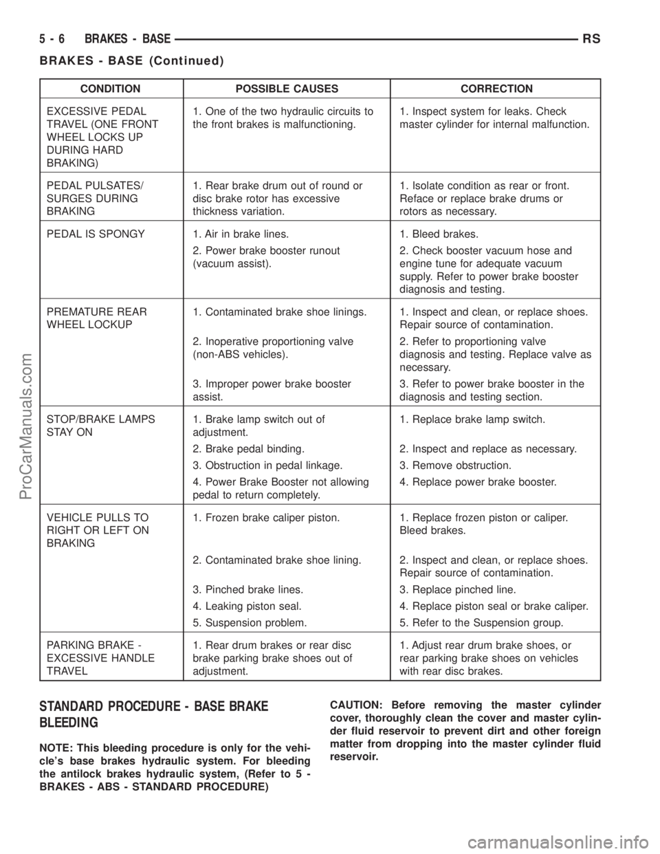
CONDITION POSSIBLE CAUSES CORRECTION
EXCESSIVE PEDAL
TRAVEL (ONE FRONT
WHEEL LOCKS UP
DURING HARD
BRAKING)1. One of the two hydraulic circuits to
the front brakes is malfunctioning.1. Inspect system for leaks. Check
master cylinder for internal malfunction.
PEDAL PULSATES/
SURGES DURING
BRAKING1. Rear brake drum out of round or
disc brake rotor has excessive
thickness variation.1. Isolate condition as rear or front.
Reface or replace brake drums or
rotors as necessary.
PEDAL IS SPONGY 1. Air in brake lines. 1. Bleed brakes.
2. Power brake booster runout
(vacuum assist).2. Check booster vacuum hose and
engine tune for adequate vacuum
supply. Refer to power brake booster
diagnosis and testing.
PREMATURE REAR
WHEEL LOCKUP1. Contaminated brake shoe linings. 1. Inspect and clean, or replace shoes.
Repair source of contamination.
2. Inoperative proportioning valve
(non-ABS vehicles).2. Refer to proportioning valve
diagnosis and testing. Replace valve as
necessary.
3. Improper power brake booster
assist.3. Refer to power brake booster in the
diagnosis and testing section.
STOP/BRAKE LAMPS
S TAY O N1. Brake lamp switch out of
adjustment.1. Replace brake lamp switch.
2. Brake pedal binding. 2. Inspect and replace as necessary.
3. Obstruction in pedal linkage. 3. Remove obstruction.
4. Power Brake Booster not allowing
pedal to return completely.4. Replace power brake booster.
VEHICLE PULLS TO
RIGHT OR LEFT ON
BRAKING1. Frozen brake caliper piston. 1. Replace frozen piston or caliper.
Bleed brakes.
2. Contaminated brake shoe lining. 2. Inspect and clean, or replace shoes.
Repair source of contamination.
3. Pinched brake lines. 3. Replace pinched line.
4. Leaking piston seal. 4. Replace piston seal or brake caliper.
5. Suspension problem. 5. Refer to the Suspension group.
PARKING BRAKE -
EXCESSIVE HANDLE
TRAVEL1. Rear drum brakes or rear disc
brake parking brake shoes out of
adjustment.1. Adjust rear drum brake shoes, or
rear parking brake shoes on vehicles
with rear disc brakes.
STANDARD PROCEDURE - BASE BRAKE
BLEEDING
NOTE: This bleeding procedure is only for the vehi-
cle's base brakes hydraulic system. For bleeding
the antilock brakes hydraulic system, (Refer to 5 -
BRAKES - ABS - STANDARD PROCEDURE)CAUTION: Before removing the master cylinder
cover, thoroughly clean the cover and master cylin-
der fluid reservoir to prevent dirt and other foreign
matter from dropping into the master cylinder fluid
reservoir.
5 - 6 BRAKES - BASERS
BRAKES - BASE (Continued)
ProCarManuals.com
Page 166 of 2321
NOTE: The following wheel sequence should be
used when bleeding the brake hydraulic system.
The use of this wheel sequence will ensure ade-
quate removal of all trapped air from the brake
hydraulic system.
²Left Rear Wheel
²Right Front Wheel
²Right Rear Wheel
²Left Front Wheel
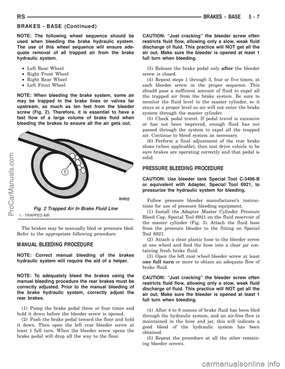
NOTE: When bleeding the brake system, some air
may be trapped in the brake lines or valves far
upstream, as much as ten feet from the bleeder
screw (Fig. 2). Therefore, it is essential to have a
fast flow of a large volume of brake fluid when
bleeding the brakes to ensure all the air gets out.
The brakes may be manually bled or pressure bled.
Refer to the appropriate following procedure.
MANUAL BLEEDING PROCEDURE
NOTE: Correct manual bleeding of the brakes
hydraulic system will require the aid of a helper.
NOTE: To adequately bleed the brakes using the
manual bleeding procedure the rear brakes must be
correctly adjusted. Prior to the manual bleeding of
the brake hydraulic system, correctly adjust the
rear brakes.
(1) Pump the brake pedal three or four times and
hold it down before the bleeder screw is opened.
(2) Push the brake pedal toward the floor and hold
it down. Then open the left rear bleeder screw at
least 1 full turn. When the bleeder screw opens the
brake pedal will drop all the way to the floor.CAUTION: ªJust crackingº the bleeder screw often
restricts fluid flow, allowing only a slow, weak fluid
discharge of fluid. This practice will NOT get all the
air out. Make sure the bleeder is opened at least 1
full turn when bleeding.
(3) Release the brake pedal onlyafterthe bleeder
screw is closed.
(4) Repeat steps 1 through 3, four or five times, at
each bleeder screw in the proper sequence. This
should pass a sufficient amount of fluid to expel all
the trapped air from the brake system. Be sure to
monitor the fluid level in the master cylinder, so it
stays at a proper level so air will not enter the brake
system through the master cylinder.
(5) Check pedal travel. If pedal travel is excessive
or has not been improved, enough fluid has not
passed through the system to expel all the trapped
air. Continue to bleed system as necessary.
(6) Perform a final adjustment of the rear brake
shoes (when applicable), then test drive vehicle to be
sure brakes are operating correctly and that pedal is
solid.
PRESSURE BLEEDING PROCEDURE
CAUTION: Use bleeder tank Special Tool C-3496-B
or equivalent with Adapter, Special Tool 6921, to
pressurize the hydraulic system for bleeding.
Follow pressure bleeder manufacturer's instruc-
tions for use of pressure bleeding equipment.
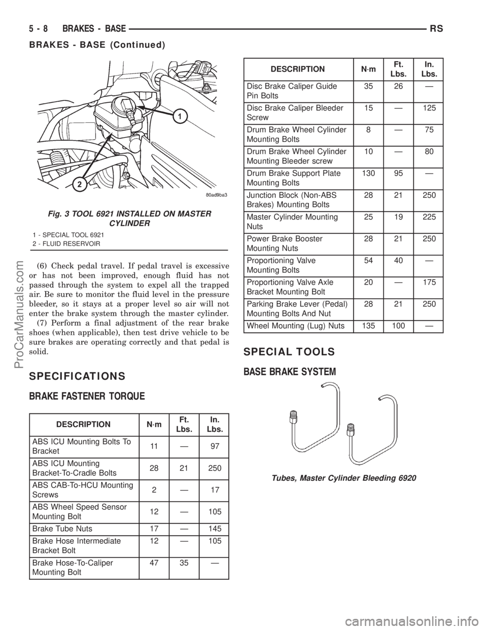
(1) Install the Adapter Master Cylinder Pressure
Bleed Cap, Special Tool 6921 on the fluid reservoir of
the master cylinder (Fig. 3). Attach the fluid hose
from the pressure bleeder to the fitting on Special
Tool 6921.
(2) Attach a clear plastic hose to the bleeder screw
at one wheel and feed the hose into a clear jar con-
taining fresh brake fluid.
(3) Open the left rear wheel bleeder screw at least
one full turnor more to obtain an adequate flow of
brake fluid.
CAUTION: ªJust crackingº the bleeder screw often
restricts fluid flow, allowing only a slow, weak fluid
discharge of fluid. This practice will NOT get all the
air out. Make sure the bleeder is opened at least 1
full turn when bleeding.
(4) After 4 to 8 ounces of brake fluid has been bled
through the hydraulic system, and an air-free flow is
maintained in the hose and jar, this will indicate a
good bleed of the hydraulic system has been
obtained.
(5) Repeat the procedure at all the other remain-
ing bleeder screws.
Fig. 2 Trapped Air In Brake Fluid Line
1 - TRAPPED AIR
RSBRAKES - BASE5-7
BRAKES - BASE (Continued)
ProCarManuals.com
Page 167 of 2321
(6) Check pedal travel. If pedal travel is excessive
or has not been improved, enough fluid has not
passed through the system to expel all the trapped
air. Be sure to monitor the fluid level in the pressure
bleeder, so it stays at a proper level so air will not
enter the brake system through the master cylinder.
(7) Perform a final adjustment of the rear brake
shoes (when applicable), then test drive vehicle to be
sure brakes are operating correctly and that pedal is
solid.
SPECIFICATIONS
BRAKE FASTENER TORQUE
DESCRIPTION N´mFt.
Lbs.In.
Lbs.
ABS ICU Mounting Bolts To
Bracket11 Ð 9 7
ABS ICU Mounting
Bracket-To-Cradle Bolts28 21 250
ABS CAB-To-HCU Mounting
Screws2Ð17
ABS Wheel Speed Sensor
Mounting Bolt12 Ð 105
Brake Tube Nuts 17 Ð 145
Brake Hose Intermediate
Bracket Bolt12 Ð 105
Brake Hose-To-Caliper
Mounting Bolt47 35 Ð
DESCRIPTION N´mFt.
Lbs.In.
Lbs.
Disc Brake Caliper Guide
Pin Bolts35 26 Ð
Disc Brake Caliper Bleeder
Screw15 Ð 125
Drum Brake Wheel Cylinder
Mounting Bolts8Ð75
Drum Brake Wheel Cylinder
Mounting Bleeder screw10 Ð 80
Drum Brake Support Plate
Mounting Bolts130 95 Ð
Junction Block (Non-ABS
Brakes) Mounting Bolts28 21 250
Master Cylinder Mounting
Nuts25 19 225
Power Brake Booster
Mounting Nuts28 21 250
Proportioning Valve
Mounting Bolts54 40 Ð
Proportioning Valve Axle
Bracket Mounting Bolt20 Ð 175
Parking Brake Lever (Pedal)
Mounting Bolts And Nut28 21 250
Wheel Mounting (Lug) Nuts 135 100 Ð
SPECIAL TOOLS
BASE BRAKE SYSTEM
Fig. 3 TOOL 6921 INSTALLED ON MASTER
CYLINDER
1 - SPECIAL TOOL 6921
2 - FLUID RESERVOIR
Tubes, Master Cylinder Bleeding 6920
5 - 8 BRAKES - BASERS
BRAKES - BASE (Continued)
ProCarManuals.com
Page 168 of 2321
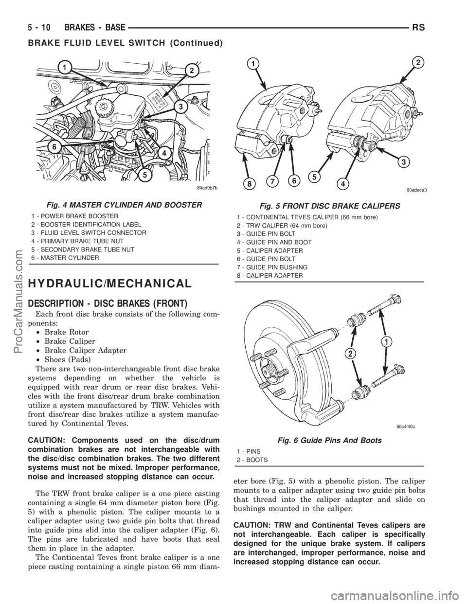
BRAKE FLUID LEVEL SWITCH
DESCRIPTION
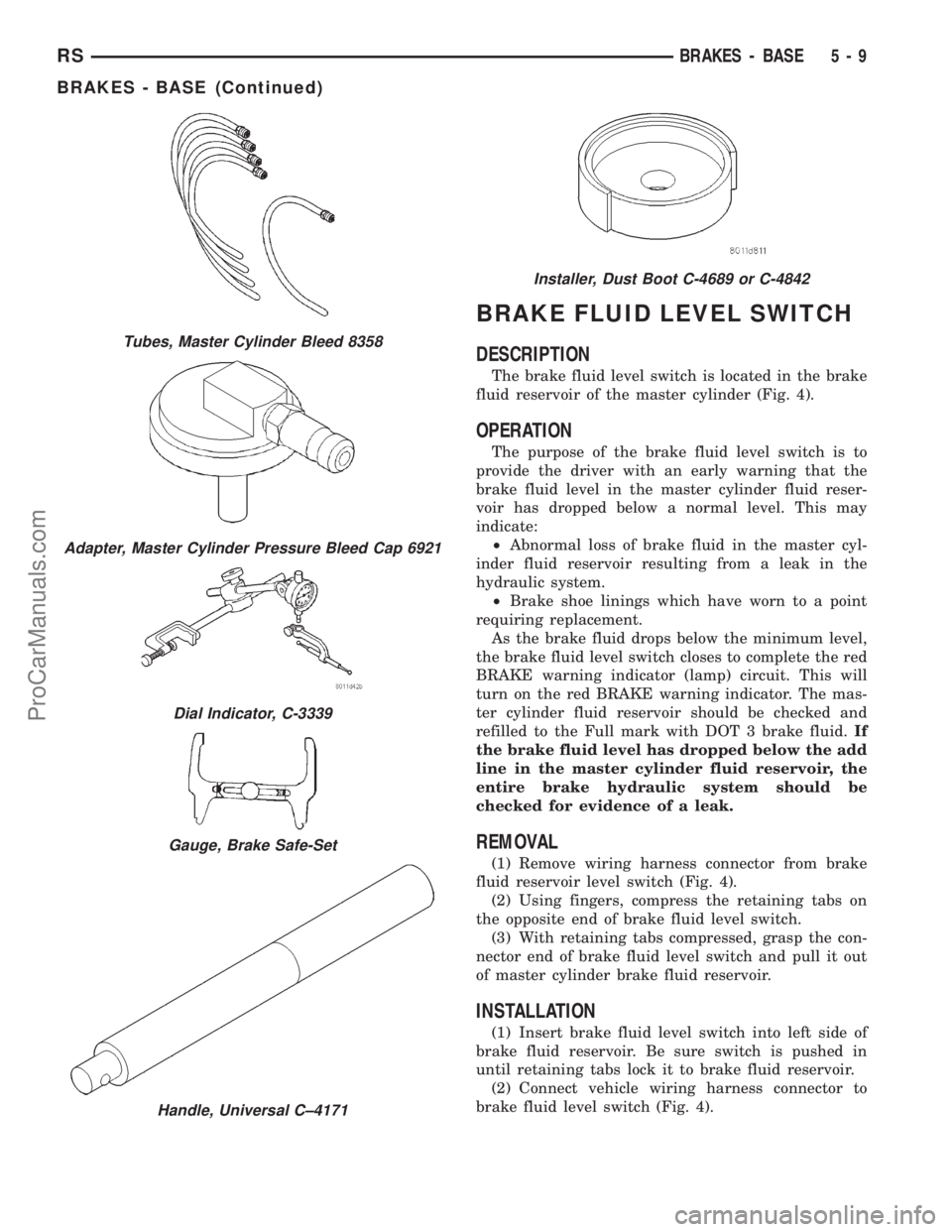
The brake fluid level switch is located in the brake
fluid reservoir of the master cylinder (Fig. 4).
OPERATION
The purpose of the brake fluid level switch is to
provide the driver with an early warning that the
brake fluid level in the master cylinder fluid reser-
voir has dropped below a normal level. This may
indicate:
²Abnormal loss of brake fluid in the master cyl-
inder fluid reservoir resulting from a leak in the
hydraulic system.
²Brake shoe linings which have worn to a point
requiring replacement.
As the brake fluid drops below the minimum level,
the brake fluid level switch closes to complete the red
BRAKE warning indicator (lamp) circuit. This will
turn on the red BRAKE warning indicator. The mas-
ter cylinder fluid reservoir should be checked and
refilled to the Full mark with DOT 3 brake fluid.If
the brake fluid level has dropped below the add
line in the master cylinder fluid reservoir, the
entire brake hydraulic system should be
checked for evidence of a leak.
REMOVAL
(1) Remove wiring harness connector from brake
fluid reservoir level switch (Fig. 4).
(2) Using fingers, compress the retaining tabs on
the opposite end of brake fluid level switch.
(3) With retaining tabs compressed, grasp the con-
nector end of brake fluid level switch and pull it out
of master cylinder brake fluid reservoir.
INSTALLATION
(1) Insert brake fluid level switch into left side of
brake fluid reservoir. Be sure switch is pushed in
until retaining tabs lock it to brake fluid reservoir.
(2) Connect vehicle wiring harness connector to
brake fluid level switch (Fig. 4).
Tubes, Master Cylinder Bleed 8358
Adapter, Master Cylinder Pressure Bleed Cap 6921
Dial Indicator, C-3339
Gauge, Brake Safe-Set
Handle, Universal C±4171
Installer, Dust Boot C-4689 or C-4842
RSBRAKES - BASE5-9
BRAKES - BASE (Continued)
ProCarManuals.com
Page 169 of 2321
HYDRAULIC/MECHANICAL
DESCRIPTION - DISC BRAKES (FRONT)
Each front disc brake consists of the following com-
ponents:
²Brake Rotor
²Brake Caliper
²Brake Caliper Adapter
²Shoes (Pads)
There are two non-interchangeable front disc brake
systems depending on whether the vehicle is
equipped with rear drum or rear disc brakes. Vehi-
cles with the front disc/rear drum brake combination
utilize a system manufactured by TRW. Vehicles with
front disc/rear disc brakes utilize a system manufac-
tured by Continental Teves.
CAUTION: Components used on the disc/drum
combination brakes are not interchangeable with
the disc/disc combination brakes. The two different
systems must not be mixed. Improper performance,
noise and increased stopping distance can occur.
The TRW front brake caliper is a one piece casting
containing a single 64 mm diameter piston bore (Fig.
5) with a phenolic piston. The caliper mounts to a
caliper adapter using two guide pin bolts that thread
into guide pins slid into the caliper adapter (Fig. 6).
The pins are lubricated and have boots that seal
them in place in the adapter.
The Continental Teves front brake caliper is a one
piece casting containing a single piston 66 mm diam-eter bore (Fig. 5) with a phenolic piston. The caliper
mounts to a caliper adapter using two guide pin bolts
that thread into the caliper adapter and slide on
bushings mounted in the caliper.
CAUTION: TRW and Continental Teves calipers are
not interchangeable. Each caliper is specifically
designed for the unique brake system. If calipers
are interchanged, improper performance, noise and
increased stopping distance can occur.
Fig. 4 MASTER CYLINDER AND BOOSTER
1 - POWER BRAKE BOOSTER
2 - BOOSTER IDENTIFICATION LABEL
3 - FLUID LEVEL SWITCH CONNECTOR
4 - PRIMARY BRAKE TUBE NUT
5 - SECONDARY BRAKE TUBE NUT
6 - MASTER CYLINDER
Fig. 5 FRONT DISC BRAKE CALIPERS
1 - CONTINENTAL TEVES CALIPER (66 mm bore)
2 - TRW CALIPER (64 mm bore)
3 - GUIDE PIN BOLT
4 - GUIDE PIN AND BOOT
5 - CALIPER ADAPTER
6 - GUIDE PIN BOLT
7 - GUIDE PIN BUSHING
8 - CALIPER ADAPTER
Fig. 6 Guide Pins And Boots
1 - PINS
2 - BOOTS
5 - 10 BRAKES - BASERS
BRAKE FLUID LEVEL SWITCH (Continued)
ProCarManuals.com
Page 170 of 2321
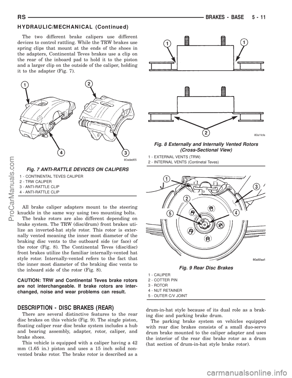
The two different brake calipers use different
devices to control rattling. While the TRW brakes use
spring clips that mount at the ends of the shoes in
the adapters, Continental Teves brakes use a clip on
the rear of the inboard pad to hold it to the piston
and a larger clip on the outside of the caliper, holding
it to the adapter (Fig. 7).
All brake caliper adapters mount to the steering
knuckle in the same way using two mounting bolts.
The brake rotors are also different depending on
brake system. The TRW (disc/drum) front brakes uti-
lize an inverted-hat style rotor. This rotor is exter-
nally vented meaning the inner most diameter of the
braking disc vents to the outboard side (or face) of
the rotor (Fig. 8). The Continental Teves (disc/disc)
front brakes utilize the familiar internally-vented hat
style rotor. Internally-vented refers to the fact that
the inner most diameter of the braking disc vents to
the inboard side of the rotor (Fig. 8).
CAUTION: TRW and Continental Teves brake rotors
are not interchangeable. If brake rotors are inter-
changed, noise and wear problems can result.
DESCRIPTION - DISC BRAKES (REAR)
There are several distinctive features to the rear
disc brakes on this vehicle (Fig. 9). The single piston,
floating caliper rear disc brake system includes a hub
and bearing assembly, adapter, rotor, caliper, and
brake shoes.
This vehicle is equipped with a caliper having a 42
mm (1.65 in.) piston and uses a 15 inch solid non-
vented brake rotor. The brake rotor is described as adrum-in-hat style because of its dual role as a brak-
ing disc and parking brake drum.
The parking brake system on vehicles equipped
with rear disc brakes consists of a small duo-servo
drum brake mounted to the caliper adapter and uses
the interior of the rear disc brake rotor as a drum
(hat section of drum-in-hat style brake rotor).
Fig. 7 ANTI-RATTLE DEVICES ON CALIPERS
1 - CONTINENTAL TEVES CALIPER
2 - TRW CALIPER
3 - ANTI-RATTLE CLIP
4 - ANTI-RATTLE CLIP
Fig. 8 Externally and Internally Vented Rotors
(Cross-Sectional View)
1 - EXTERNAL VENTS (TRW)
2 - INTERNAL VENTS (Continetal Teves)
Fig. 9 Rear Disc Brakes
1 - CALIPER
2 - COTTER PIN
3 - ROTOR
4 - NUT RETAINER
5 - OUTER C/V JOINT
RSBRAKES - BASE5-11
HYDRAULIC/MECHANICAL (Continued)
ProCarManuals.com