DODGE TOWN AND COUNTRY 2001 Service Manual
Manufacturer: DODGE, Model Year: 2001, Model line: TOWN AND COUNTRY, Model: DODGE TOWN AND COUNTRY 2001Pages: 2321, PDF Size: 68.09 MB
Page 141 of 2321
ASSEMBLY
(1) Install output flange seals using tools C4171
and 8493 (Fig. 15).
(2) Install large overrunning clutch housing o-ring
to differential assembly (Fig. 14).
(3) Install shim to differential pinion shaft (Fig.
16).
(4) Install viscous coupler to differential pinion
shaft (Fig. 17).
(5) Install overrunning clutch assembly to viscous
coupler (Fig. 18).
(6) Install washer to overrunning clutch (Fig. 14).
(7) Install o-ring to overrunning clutch (Fig. 14).
(8) Align overrunning clutch ground tab to 12
o'clock position (Fig. 19).
(9) Install overrunning clutch housing into posi-
tion, making sure ground tab engages with notch in
housing (Fig. 20).
(10) Install and torque overrunning clutch hous-
ing-to-differential assembly bolts (Fig. 21) to 60 N´m
(44 ft. lbs.).
(11) Install input flange seal using tool 8802 (Fig.
22).
(12) Install flange/shield assembly (Fig. 23).
(13) Install input flange washer and nut. Using
tool 6958 (Fig. 24), torque nut to 135 N´m (100 ft.
lbs.).
(14) Install torque arm assembly into position.
Install and torque torque arm-to-differential assem-
bly bolts (Fig. 25) to 60 N´m (44 ft. lbs.).
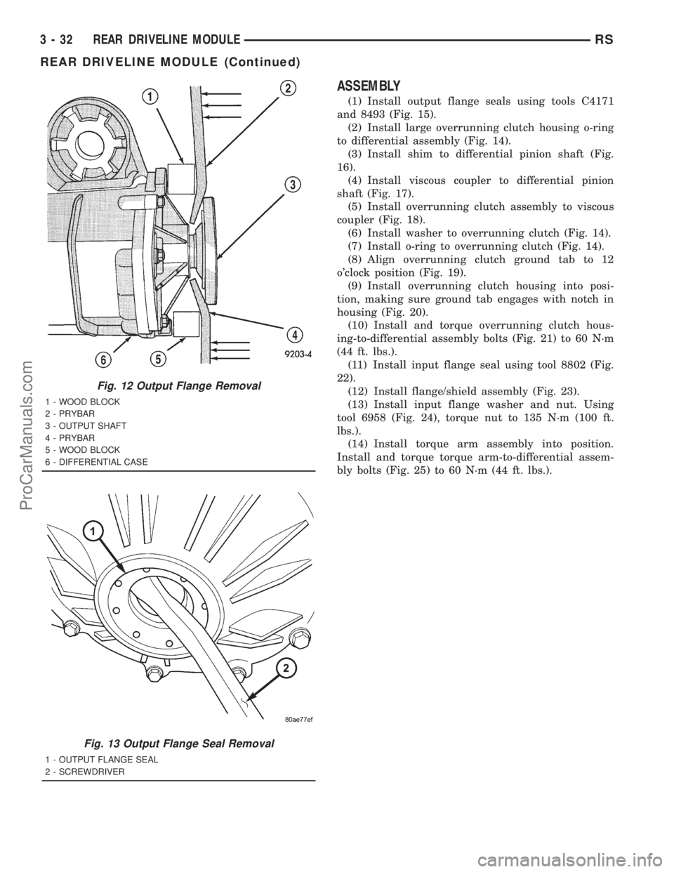
Fig. 12 Output Flange Removal
1 - WOOD BLOCK
2 - PRYBAR
3 - OUTPUT SHAFT
4 - PRYBAR
5 - WOOD BLOCK
6 - DIFFERENTIAL CASE
Fig. 13 Output Flange Seal Removal
1 - OUTPUT FLANGE SEAL
2 - SCREWDRIVER
3 - 32 REAR DRIVELINE MODULERS
REAR DRIVELINE MODULE (Continued)
ProCarManuals.com
Page 142 of 2321
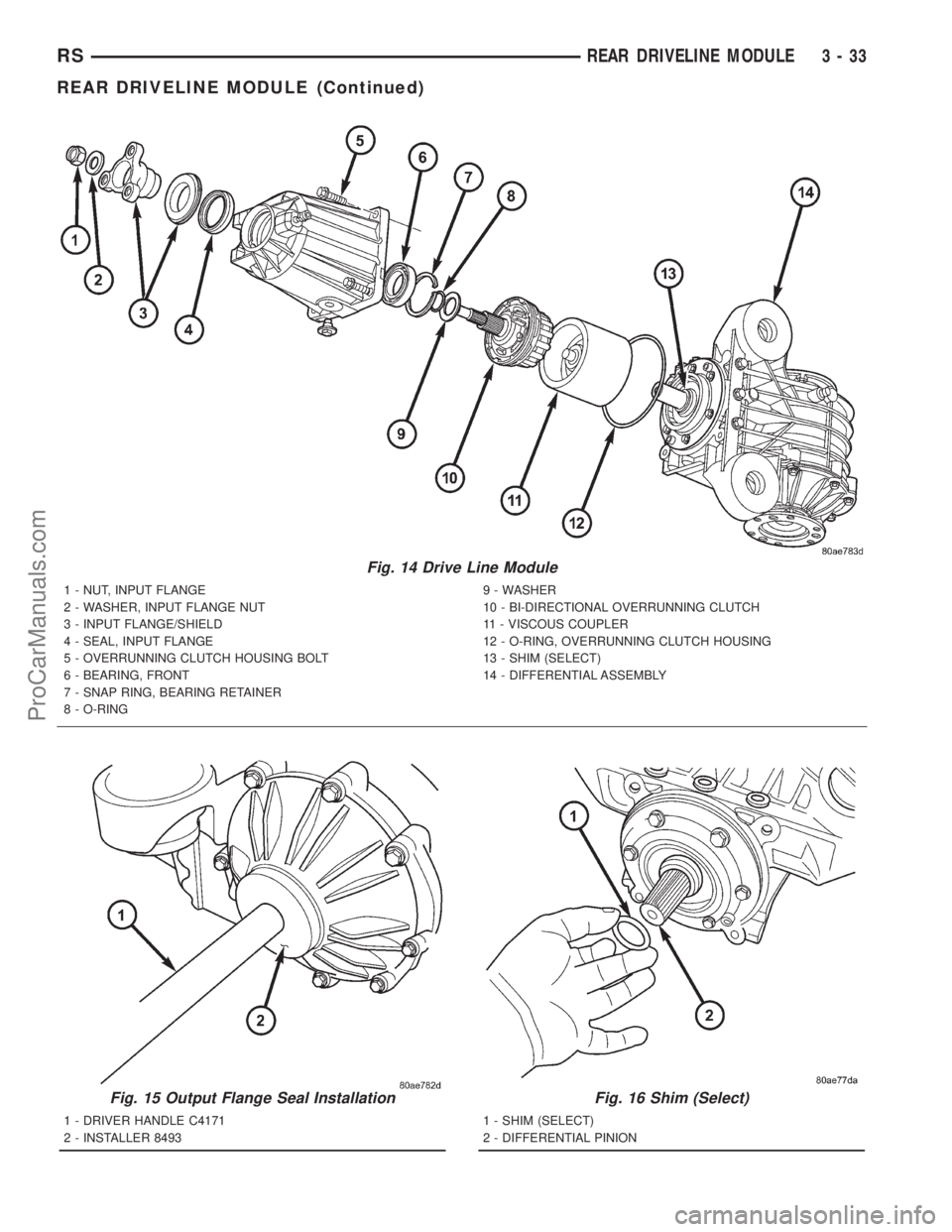
Fig. 14 Drive Line Module
1 - NUT, INPUT FLANGE
2 - WASHER, INPUT FLANGE NUT
3 - INPUT FLANGE/SHIELD
4 - SEAL, INPUT FLANGE
5 - OVERRUNNING CLUTCH HOUSING BOLT
6 - BEARING, FRONT
7 - SNAP RING, BEARING RETAINER
8 - O-RING9 - WASHER
10 - BI-DIRECTIONAL OVERRUNNING CLUTCH
11 - VISCOUS COUPLER
12 - O-RING, OVERRUNNING CLUTCH HOUSING
13 - SHIM (SELECT)
14 - DIFFERENTIAL ASSEMBLY
Fig. 15 Output Flange Seal Installation
1 - DRIVER HANDLE C4171
2 - INSTALLER 8493
Fig. 16 Shim (Select)
1 - SHIM (SELECT)
2 - DIFFERENTIAL PINION
RSREAR DRIVELINE MODULE3-33
REAR DRIVELINE MODULE (Continued)
ProCarManuals.com
Page 143 of 2321
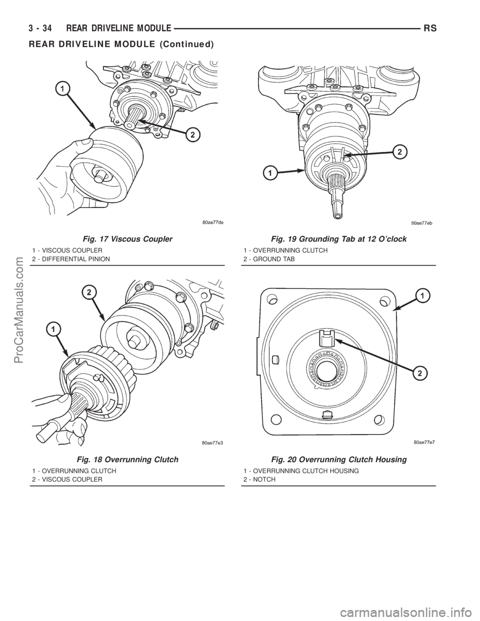
Fig. 17 Viscous Coupler
1 - VISCOUS COUPLER
2 - DIFFERENTIAL PINION
Fig. 18 Overrunning Clutch
1 - OVERRUNNING CLUTCH
2 - VISCOUS COUPLER
Fig. 19 Grounding Tab at 12 O'clock
1 - OVERRUNNING CLUTCH
2 - GROUND TAB
Fig. 20 Overrunning Clutch Housing
1 - OVERRUNNING CLUTCH HOUSING
2 - NOTCH
3 - 34 REAR DRIVELINE MODULERS
REAR DRIVELINE MODULE (Continued)
ProCarManuals.com
Page 144 of 2321
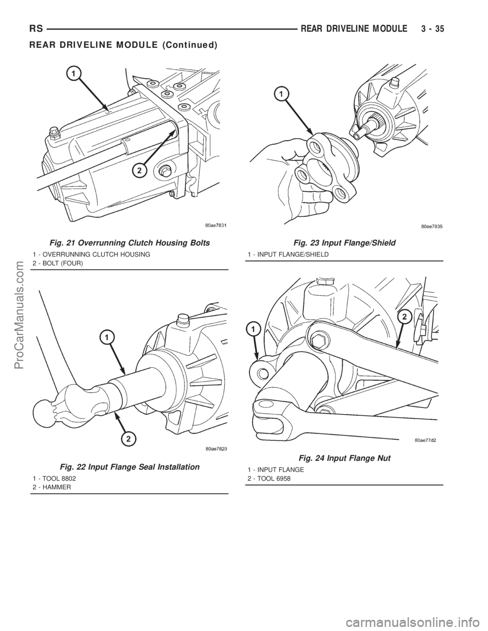
Fig. 21 Overrunning Clutch Housing Bolts
1 - OVERRUNNING CLUTCH HOUSING
2 - BOLT (FOUR)
Fig. 22 Input Flange Seal Installation
1 - TOOL 8802
2 - HAMMER
Fig. 23 Input Flange/Shield
1 - INPUT FLANGE/SHIELD
Fig. 24 Input Flange Nut
1 - INPUT FLANGE
2 - TOOL 6958
RSREAR DRIVELINE MODULE3-35
REAR DRIVELINE MODULE (Continued)
ProCarManuals.com
Page 145 of 2321
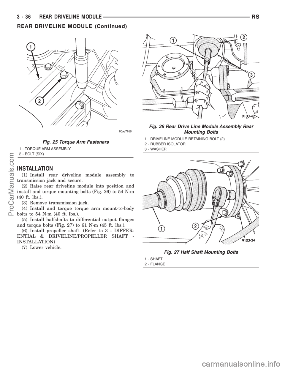
INSTALLATION
(1) Install rear driveline module assembly to
transmission jack and secure.
(2) Raise rear driveline module into position and
install and torque mounting bolts (Fig. 26) to 54 N´m
(40 ft. lbs.).
(3) Remove transmission jack.
(4) Install and torque torque arm mount-to-body
bolts to 54 N´m (40 ft. lbs.).
(5) Install halfshafts to differential output flanges
and torque bolts (Fig. 27) to 61 N´m (45 ft. lbs.).
(6) Install propeller shaft. (Refer to 3 - DIFFER-
ENTIAL & DRIVELINE/PROPELLER SHAFT -
INSTALLATION)
(7) Lower vehicle.
Fig. 25 Torque Arm Fasteners
1 - TORQUE ARM ASSEMBLY
2 - BOLT (SIX)
Fig. 26 Rear Drive Line Module Assembly Rear
Mounting Bolts
1 - DRIVELINE MODULE RETAINING BOLT (2)
2 - RUBBER ISOLATOR
3 - WASHER
Fig. 27 Half Shaft Mounting Bolts
1 - SHAFT
2 - FLANGE
3 - 36 REAR DRIVELINE MODULERS
REAR DRIVELINE MODULE (Continued)
ProCarManuals.com
Page 146 of 2321
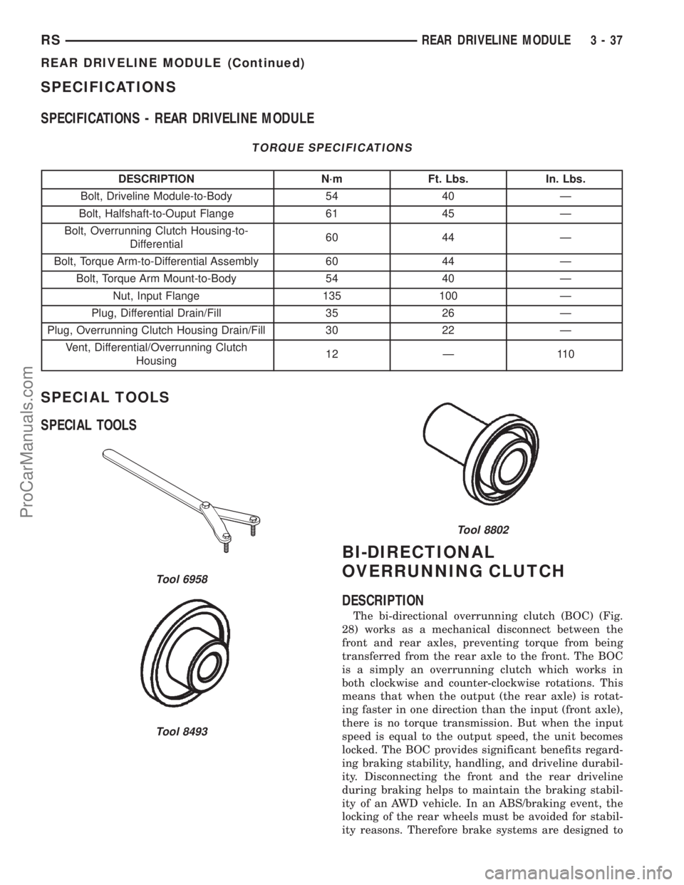
SPECIFICATIONS
SPECIFICATIONS - REAR DRIVELINE MODULE
TORQUE SPECIFICATIONS
DESCRIPTION N´m Ft. Lbs. In. Lbs.
Bolt, Driveline Module-to-Body 54 40 Ð
Bolt, Halfshaft-to-Ouput Flange 61 45 Ð
Bolt, Overrunning Clutch Housing-to-
Differential60 44 Ð
Bolt, Torque Arm-to-Differential Assembly 60 44 Ð
Bolt, Torque Arm Mount-to-Body 54 40 Ð
Nut, Input Flange 135 100 Ð
Plug, Differential Drain/Fill 35 26 Ð
Plug, Overrunning Clutch Housing Drain/Fill 30 22 Ð
Vent, Differential/Overrunning Clutch
Housing12 Ð 110
SPECIAL TOOLS
SPECIAL TOOLS
BI-DIRECTIONAL
OVERRUNNING CLUTCH
DESCRIPTION
The bi-directional overrunning clutch (BOC) (Fig.
28) works as a mechanical disconnect between the
front and rear axles, preventing torque from being
transferred from the rear axle to the front. The BOC
is a simply an overrunning clutch which works in
both clockwise and counter-clockwise rotations. This
means that when the output (the rear axle) is rotat-
ing faster in one direction than the input (front axle),
there is no torque transmission. But when the input
speed is equal to the output speed, the unit becomes
locked. The BOC provides significant benefits regard-
ing braking stability, handling, and driveline durabil-
ity. Disconnecting the front and the rear driveline
during braking helps to maintain the braking stabil-
ity of an AWD vehicle. In an ABS/braking event, the
locking of the rear wheels must be avoided for stabil-
ity reasons. Therefore brake systems are designed to
Tool 6958
Tool 8493
Tool 8802
RSREAR DRIVELINE MODULE3-37
REAR DRIVELINE MODULE (Continued)
ProCarManuals.com
Page 147 of 2321
lock the front wheels first. Any torque transfer from
the rear axle to the front axle disturbs the ABS/brak-
ing system and causes potential instabilities on a
slippery surface. The BOC de-couples the rear driv-
eline as soon the rear wheels begin to spin faster
than the front wheels (front wheels locked) in order
to provide increased braking stability. Furthermore
the BOC also reduces the likelihood of throttle off
over-steer during cornering. In a throttle off maneu-
ver, the BOC once again de-couples the rear driveline
forcing all the engine brake torque to the front
wheels. This eliminates the chance of lateral slip on
the rear axle and increases it on the front. The vehi-
cle will therefore tend to understeer, a situation
which is considered easier to manage in most circum-
stances. During this maneuver, and during the ABS
braking event, the BOC does not transmit torque
through to the rear wheels. The rear driveline mod-
ule, with the BOC, will perform the same as a front
wheel drive vehicle during these events. The gear
ratio offset between the front and rear differentials
force the BOC into the overrunning mode most of the
time. This allows BOC to significantly reduce the
rolling resistance of the vehicle, which improves fuel
consumption, allows the downsizing of the driveline
components, and prevents the PTU and propshaft
joints from overheating.
OPERATION
In order to achieve all-wheel drive operation in
reverse, the overrunning clutch locking functional
direction must be reversible. The bi-directional over-
running clutch (BOC) changes the operational mode
direction depending on the propeller shaft direction.
The propeller shaft rotates in the clockwise (when
viewed from the front) direction when the vehicle is
moving forward, which indexes the BOC to the for-
ward overrunning position. When the vehicle is in
reverse, the propeller shaft will rotate counter-clock-
wise and index the BOC to the reverse overrunning
position.
The BOC acts as a mechanical stator. It is active
(transmitting torque), or it is not active and in over-
running mode (not transmitting torque). This ªall or
nothingº approach to torque transfer would cause a
sudden application of all available power to the rear
wheels, which is not desirable. Therefore it is run in
series with a viscous coupler to smooth, dampen, and
limit the transmission of torque to the rear axle and
to prevent a step style torque input to the rear axle.
STEADY STATE, LOW TO MODERATE SPEED, NO
FRONT WHEEL SLIP, FORWARD DIRECTION
During normal driving conditions, (no wheel slip),
the inner shaft (front axle) and outer race (viscous
coupler) are running at different speeds due to the
different gear ratios between the front and rear dif-
ferentials. In this condition, the outer race is always
spinning faster (overdriving between 5-32 rpm) than
the inner shaft. When the BOC (Fig. 29) is running
under these conditions, at low vehicle speeds the
drag shoes and the cage keep the rollers up on the
left side (forward side) of the inner shaft flats. This is
what is known as ªoverrunning mode.º Notice that
when the clutch is in overrunning mode, the rollers
are spinning clockwise and with the outer race, thus
no torque is being transferred.
NOTE: Low speed, forward and reverse operation is
identical, just in opposite directions. (Fig. 29)
shows forward direction in reverse the rollers are
on the other side of the flats due to a reversal of
the cage force.
TRANSIENT CONDITION (BOC LOCKED), FRONT
WHEEL SLIP, FORWARD DIRECTION
When the front wheels lose traction and begin to
slip, the propeller shaft and rear axle pinion speed
difference decreases to zero. At this point the input
shaft (cam) becomes the driving member of the BOC
(Fig. 30), compressing the rollers against the outer
race. This locks the input shaft with the outer race
and transmits torque to the housing of the viscous
coupler, that in turn transmits torque to the rear
axle pinion. It should also be noted that when the
device is locked, the inner shaft and the outer race
are rotating at the same speed. The rollers are
pinched at this point and will stay locked until a
torque reversal (no front wheel slip) occurs. When
locked, the viscous coupler slips during the torque
transfer and the amount of torque transferred is
dependent on the coupling characteristic and the
amount of front wheel slip.
3 - 38 REAR DRIVELINE MODULERS
BI-DIRECTIONAL OVERRUNNING CLUTCH (Continued)
ProCarManuals.com
Page 148 of 2321
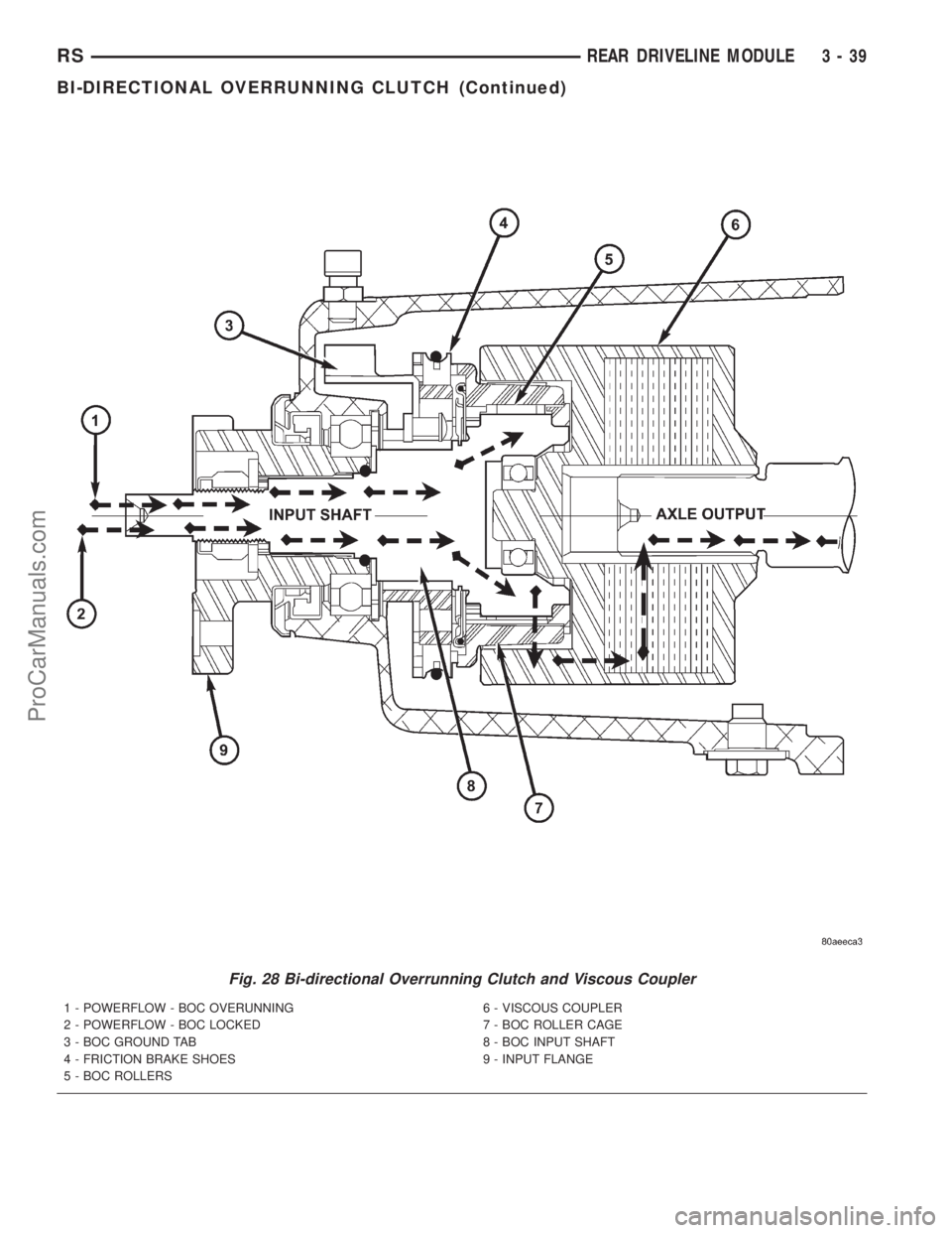
Fig. 28 Bi-directional Overrunning Clutch and Viscous Coupler
1 - POWERFLOW - BOC OVERUNNING
2 - POWERFLOW - BOC LOCKED
3 - BOC GROUND TAB
4 - FRICTION BRAKE SHOES
5 - BOC ROLLERS6 - VISCOUS COUPLER
7 - BOC ROLLER CAGE
8 - BOC INPUT SHAFT
9 - INPUT FLANGE
RSREAR DRIVELINE MODULE3-39
BI-DIRECTIONAL OVERRUNNING CLUTCH (Continued)
ProCarManuals.com
Page 149 of 2321
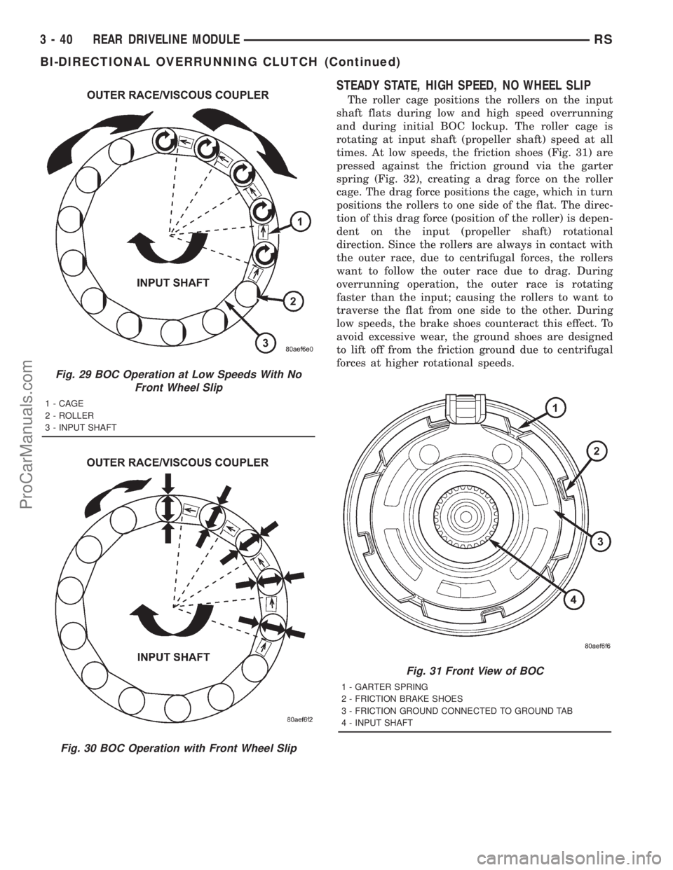
STEADY STATE, HIGH SPEED, NO WHEEL SLIP
The roller cage positions the rollers on the input
shaft flats during low and high speed overrunning
and during initial BOC lockup. The roller cage is
rotating at input shaft (propeller shaft) speed at all
times. At low speeds, the friction shoes (Fig. 31) are
pressed against the friction ground via the garter
spring (Fig. 32), creating a drag force on the roller
cage. The drag force positions the cage, which in turn
positions the rollers to one side of the flat. The direc-
tion of this drag force (position of the roller) is depen-
dent on the input (propeller shaft) rotational
direction. Since the rollers are always in contact with
the outer race, due to centrifugal forces, the rollers
want to follow the outer race due to drag. During
overrunning operation, the outer race is rotating
faster than the input; causing the rollers to want to
traverse the flat from one side to the other. During
low speeds, the brake shoes counteract this effect. To
avoid excessive wear, the ground shoes are designed
to lift off from the friction ground due to centrifugal
forces at higher rotational speeds.
Fig. 29 BOC Operation at Low Speeds With No
Front Wheel Slip
1 - CAGE
2 - ROLLER
3 - INPUT SHAFT
Fig. 30 BOC Operation with Front Wheel Slip
Fig. 31 Front View of BOC
1 - GARTER SPRING
2 - FRICTION BRAKE SHOES
3 - FRICTION GROUND CONNECTED TO GROUND TAB
4 - INPUT SHAFT
3 - 40 REAR DRIVELINE MODULERS
BI-DIRECTIONAL OVERRUNNING CLUTCH (Continued)
ProCarManuals.com
Page 150 of 2321
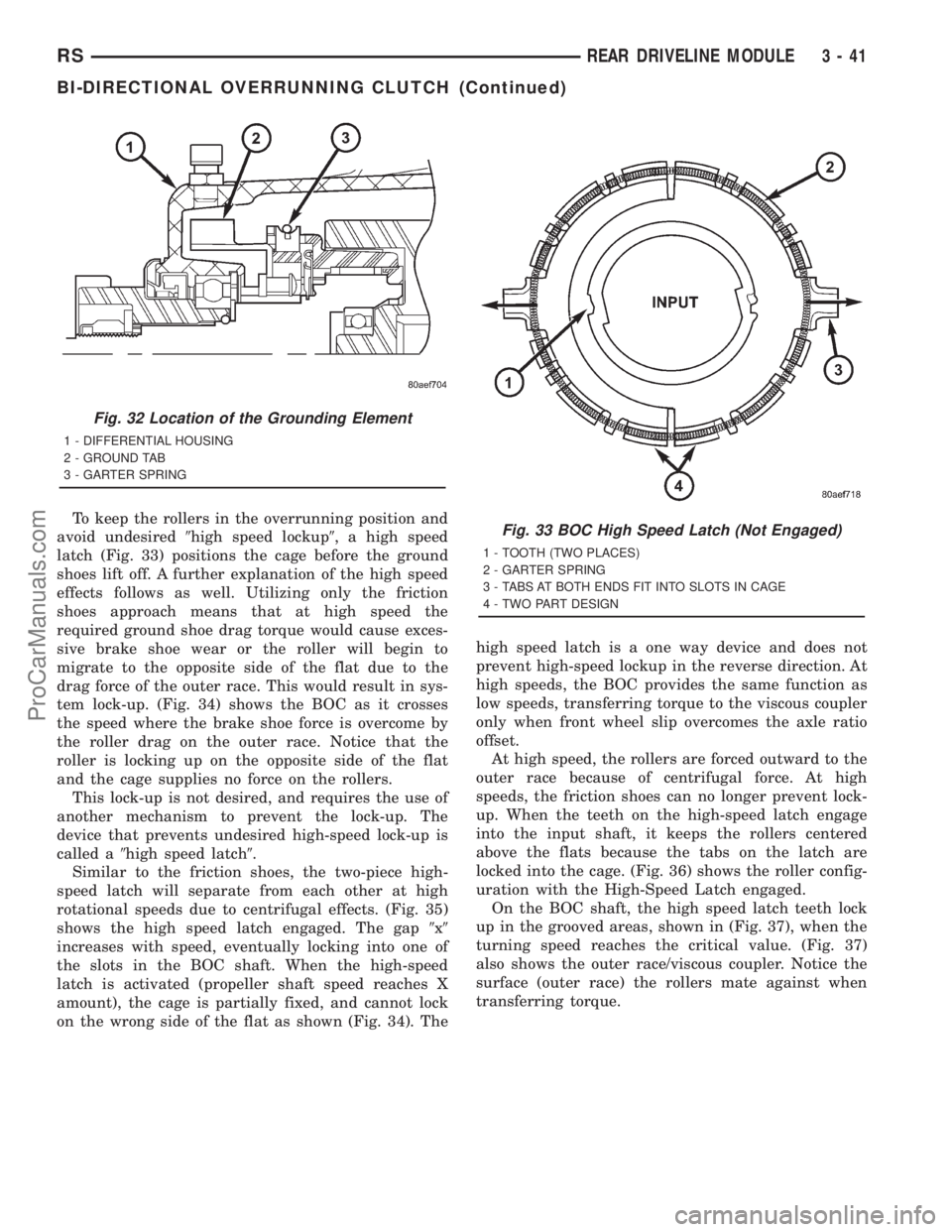
To keep the rollers in the overrunning position and
avoid undesired9high speed lockup9, a high speed
latch (Fig. 33) positions the cage before the ground
shoes lift off. A further explanation of the high speed
effects follows as well. Utilizing only the friction
shoes approach means that at high speed the
required ground shoe drag torque would cause exces-
sive brake shoe wear or the roller will begin to
migrate to the opposite side of the flat due to the
drag force of the outer race. This would result in sys-
tem lock-up. (Fig. 34) shows the BOC as it crosses
the speed where the brake shoe force is overcome by
the roller drag on the outer race. Notice that the
roller is locking up on the opposite side of the flat
and the cage supplies no force on the rollers.
This lock-up is not desired, and requires the use of
another mechanism to prevent the lock-up. The
device that prevents undesired high-speed lock-up is
called a9high speed latch9.
Similar to the friction shoes, the two-piece high-
speed latch will separate from each other at high
rotational speeds due to centrifugal effects. (Fig. 35)
shows the high speed latch engaged. The gap9x9
increases with speed, eventually locking into one of
the slots in the BOC shaft. When the high-speed
latch is activated (propeller shaft speed reaches X
amount), the cage is partially fixed, and cannot lock
on the wrong side of the flat as shown (Fig. 34). Thehigh speed latch is a one way device and does not
prevent high-speed lockup in the reverse direction. At
high speeds, the BOC provides the same function as
low speeds, transferring torque to the viscous coupler
only when front wheel slip overcomes the axle ratio
offset.
At high speed, the rollers are forced outward to the
outer race because of centrifugal force. At high
speeds, the friction shoes can no longer prevent lock-
up. When the teeth on the high-speed latch engage
into the input shaft, it keeps the rollers centered
above the flats because the tabs on the latch are
locked into the cage. (Fig. 36) shows the roller config-
uration with the High-Speed Latch engaged.
On the BOC shaft, the high speed latch teeth lock
up in the grooved areas, shown in (Fig. 37), when the
turning speed reaches the critical value. (Fig. 37)
also shows the outer race/viscous coupler. Notice the
surface (outer race) the rollers mate against when
transferring torque.
Fig. 32 Location of the Grounding Element
1 - DIFFERENTIAL HOUSING
2 - GROUND TAB
3 - GARTER SPRING
Fig. 33 BOC High Speed Latch (Not Engaged)
1 - TOOTH (TWO PLACES)
2 - GARTER SPRING
3 - TABS AT BOTH ENDS FIT INTO SLOTS IN CAGE
4 - TWO PART DESIGN
RSREAR DRIVELINE MODULE3-41
BI-DIRECTIONAL OVERRUNNING CLUTCH (Continued)
ProCarManuals.com