DODGE TOWN AND COUNTRY 2001 Service Manual
Manufacturer: DODGE, Model Year: 2001, Model line: TOWN AND COUNTRY, Model: DODGE TOWN AND COUNTRY 2001Pages: 2321, PDF Size: 68.09 MB
Page 251 of 2321

ProCarManuals.com
Page 252 of 2321
CLUTCH
TABLE OF CONTENTS
page page
CLUTCH
DESCRIPTION...........................1
DIAGNOSIS AND TESTING
DIAGNOSIS AND TESTING - CLUTCH
SYSTEM..............................4
DIAGNOSIS AND TESTING - DRIVE PLATE
MISALIGNMENT.........................7
DIAGNOSIS AND TESTING - CLUTCH
COVER AND DISC RUNOUT...............7
DIAGNOSIS AND TESTING - CLUTCH
CHATTER COMPLAINTS..................7
SPECIAL TOOLS..........................7
CLUTCH RELEASE CABLE - LHD
REMOVAL...............................7
INSTALLATION...........................9
CLUTCH RELEASE LEVER AND BEARING
REMOVAL..............................11INSTALLATION..........................12
MASTER CYLINDER - RHD
REMOVAL..............................13
INSTALLATION..........................14
MODULAR CLUTCH ASSY - 2.4L GAS
REMOVAL..............................14
INSTALLATION..........................15
SLAVE CYLINDER - RHD
REMOVAL..............................15
INSTALLATION..........................15
CLUTCH DISC AND PRESSURE PLATE - 2.5L
TD
REMOVAL..............................15
INSTALLATION..........................15
FLYWHEEL
REMOVAL..............................16
INSTALLATION..........................16
CLUTCH
DESCRIPTION
CLUTCH COMPONENTS
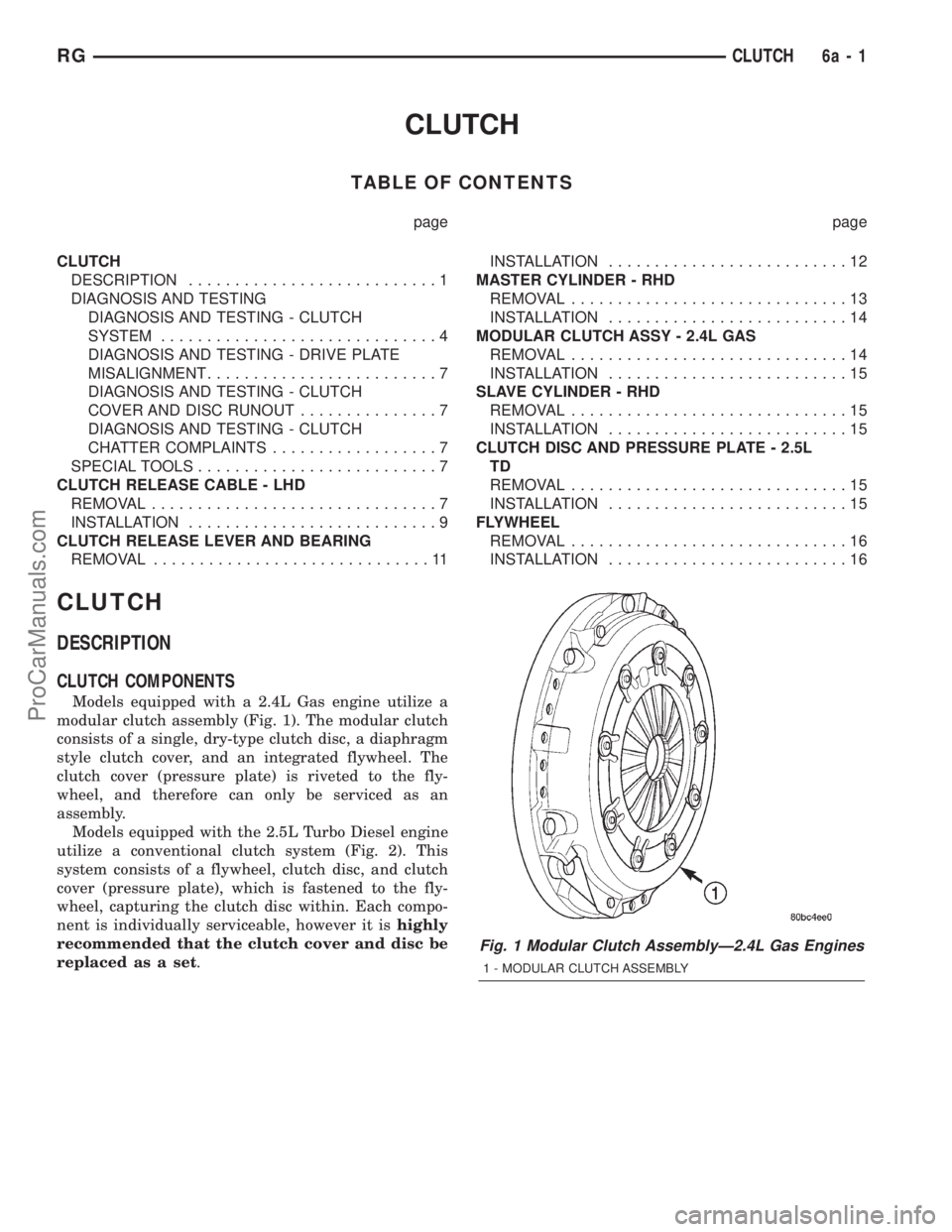
Models equipped with a 2.4L Gas engine utilize a
modular clutch assembly (Fig. 1). The modular clutch
consists of a single, dry-type clutch disc, a diaphragm
style clutch cover, and an integrated flywheel. The
clutch cover (pressure plate) is riveted to the fly-
wheel, and therefore can only be serviced as an
assembly.
Models equipped with the 2.5L Turbo Diesel engine
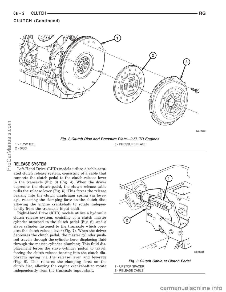
utilize a conventional clutch system (Fig. 2). This
system consists of a flywheel, clutch disc, and clutch
cover (pressure plate), which is fastened to the fly-
wheel, capturing the clutch disc within. Each compo-
nent is individually serviceable, however it ishighly
recommended that the clutch cover and disc be
replaced as a set.
Fig. 1 Modular Clutch AssemblyÐ2.4L Gas Engines
1 - MODULAR CLUTCH ASSEMBLY
RGCLUTCH6a-1
ProCarManuals.com
Page 253 of 2321
RELEASE SYSTEM
Left-Hand Drive (LHD) models utilize a cable-actu-
ated clutch release system, consisting of a cable that
connects the clutch pedal to the clutch release lever
in the transaxle (Fig. 3) (Fig. 4). When the driver
depresses the clutch pedal, the clutch release cable
pulls the release lever (Fig. 5). This forces the release
bearing into the clutch diaphragm spring via lever-
age, releasing the clamping force on the clutch disc,
allowing the engine crankshaft to rotate indepen-
dently from the transaxle input shaft.
Right-Hand Drive (RHD) models utilize a hydraulic
clutch release system, conisting of a clutch master
cylinder attached to the clutch pedal (Fig. 6), and a
slave cylinder fastened to the transaxle which oper-
ates the clutch release lever (Fig. 7). When the driver
depresses the clutch pedal, the master cylinder push-
rod travels through the cylinder bore, displacing fluid
through the master cylinder plumbing. This fluid dis-
placement forces the slave cylinder piston to travel,
forcing the clutch release bearing into the clutch dia-
phragm spring via the release lever and leverage
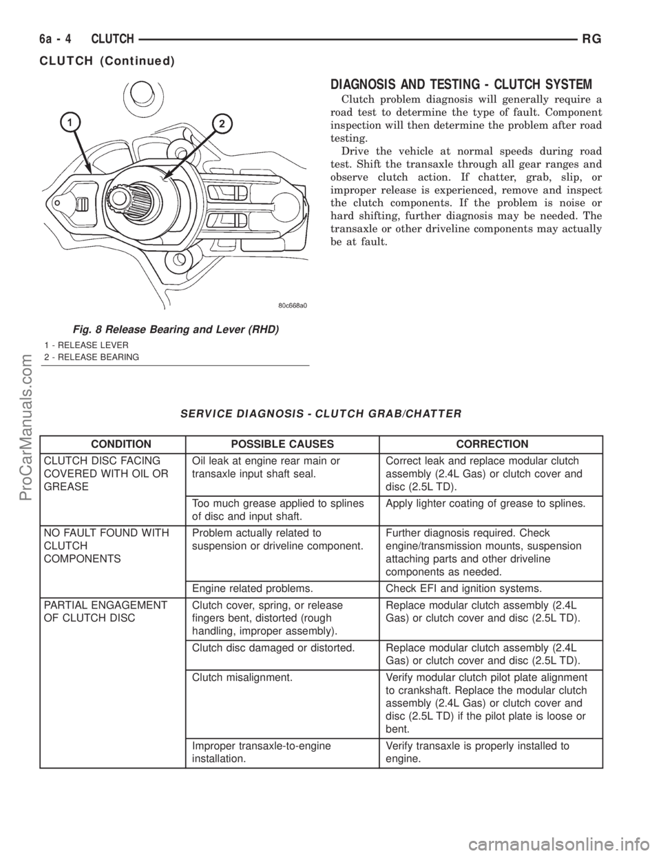
(Fig. 8). This releases the clamping force on the
clutch disc, allowing the engine crankshaft to rotate
independently from the transaxle input shaft.
Fig. 2 Clutch Disc and Pressure PlateÐ2.5L TD Engines
1 - FLYWHEEL
2 - DISC3 - PRESSURE PLATE
Fig. 3 Clutch Cable at Clutch Pedal
1 - UPSTOP SPACER
2 - RELEASE CABLE
6a - 2 CLUTCHRG
CLUTCH (Continued)
ProCarManuals.com
Page 254 of 2321
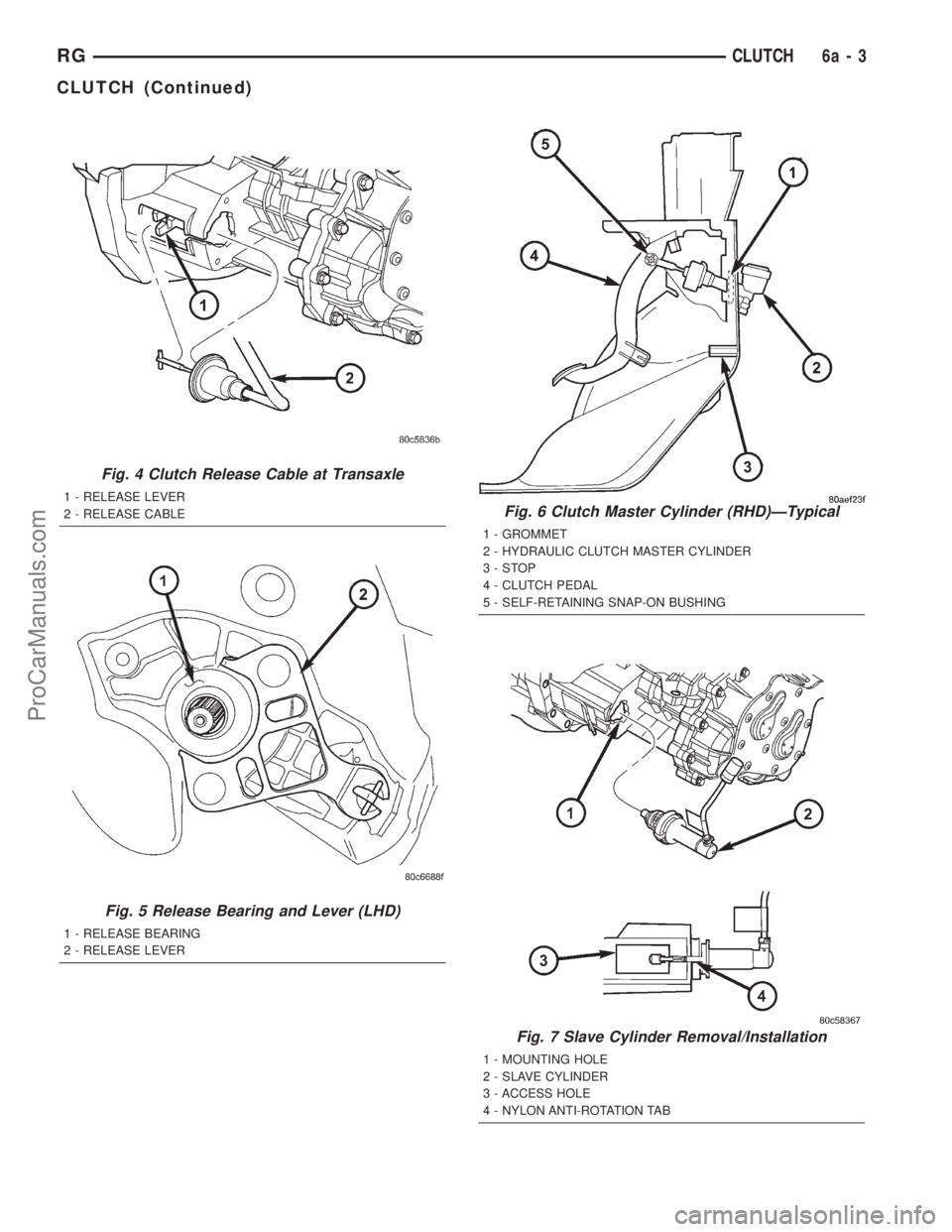
Fig. 4 Clutch Release Cable at Transaxle
1 - RELEASE LEVER
2 - RELEASE CABLE
Fig. 5 Release Bearing and Lever (LHD)
1 - RELEASE BEARING
2 - RELEASE LEVER
Fig. 6 Clutch Master Cylinder (RHD)ÐTypical
1 - GROMMET
2 - HYDRAULIC CLUTCH MASTER CYLINDER
3-STOP
4 - CLUTCH PEDAL
5 - SELF-RETAINING SNAP-ON BUSHING
Fig. 7 Slave Cylinder Removal/Installation
1 - MOUNTING HOLE
2 - SLAVE CYLINDER
3 - ACCESS HOLE
4 - NYLON ANTI-ROTATION TAB
RGCLUTCH6a-3
CLUTCH (Continued)
ProCarManuals.com
Page 255 of 2321
DIAGNOSIS AND TESTING - CLUTCH SYSTEM
Clutch problem diagnosis will generally require a
road test to determine the type of fault. Component
inspection will then determine the problem after road
testing.
Drive the vehicle at normal speeds during road
test. Shift the transaxle through all gear ranges and
observe clutch action. If chatter, grab, slip, or
improper release is experienced, remove and inspect
the clutch components. If the problem is noise or
hard shifting, further diagnosis may be needed. The
transaxle or other driveline components may actually
be at fault.
SERVICE DIAGNOSIS - CLUTCH GRAB/CHATTER
CONDITION POSSIBLE CAUSES CORRECTION
CLUTCH DISC FACING
COVERED WITH OIL OR
GREASEOil leak at engine rear main or
transaxle input shaft seal.Correct leak and replace modular clutch
assembly (2.4L Gas) or clutch cover and
disc (2.5L TD).
Too much grease applied to splines
of disc and input shaft.Apply lighter coating of grease to splines.
NO FAULT FOUND WITH
CLUTCH
COMPONENTSProblem actually related to
suspension or driveline component.Further diagnosis required. Check
engine/transmission mounts, suspension
attaching parts and other driveline
components as needed.
Engine related problems. Check EFI and ignition systems.
PARTIAL ENGAGEMENT
OF CLUTCH DISCClutch cover, spring, or release
fingers bent, distorted (rough
handling, improper assembly).Replace modular clutch assembly (2.4L
Gas) or clutch cover and disc (2.5L TD).
Clutch disc damaged or distorted. Replace modular clutch assembly (2.4L
Gas) or clutch cover and disc (2.5L TD).
Clutch misalignment. Verify modular clutch pilot plate alignment
to crankshaft. Replace the modular clutch
assembly (2.4L Gas) or clutch cover and
disc (2.5L TD) if the pilot plate is loose or
bent.
Improper transaxle-to-engine
installation.Verify transaxle is properly installed to
engine.
Fig. 8 Release Bearing and Lever (RHD)
1 - RELEASE LEVER
2 - RELEASE BEARING
6a - 4 CLUTCHRG
CLUTCH (Continued)
ProCarManuals.com
Page 256 of 2321
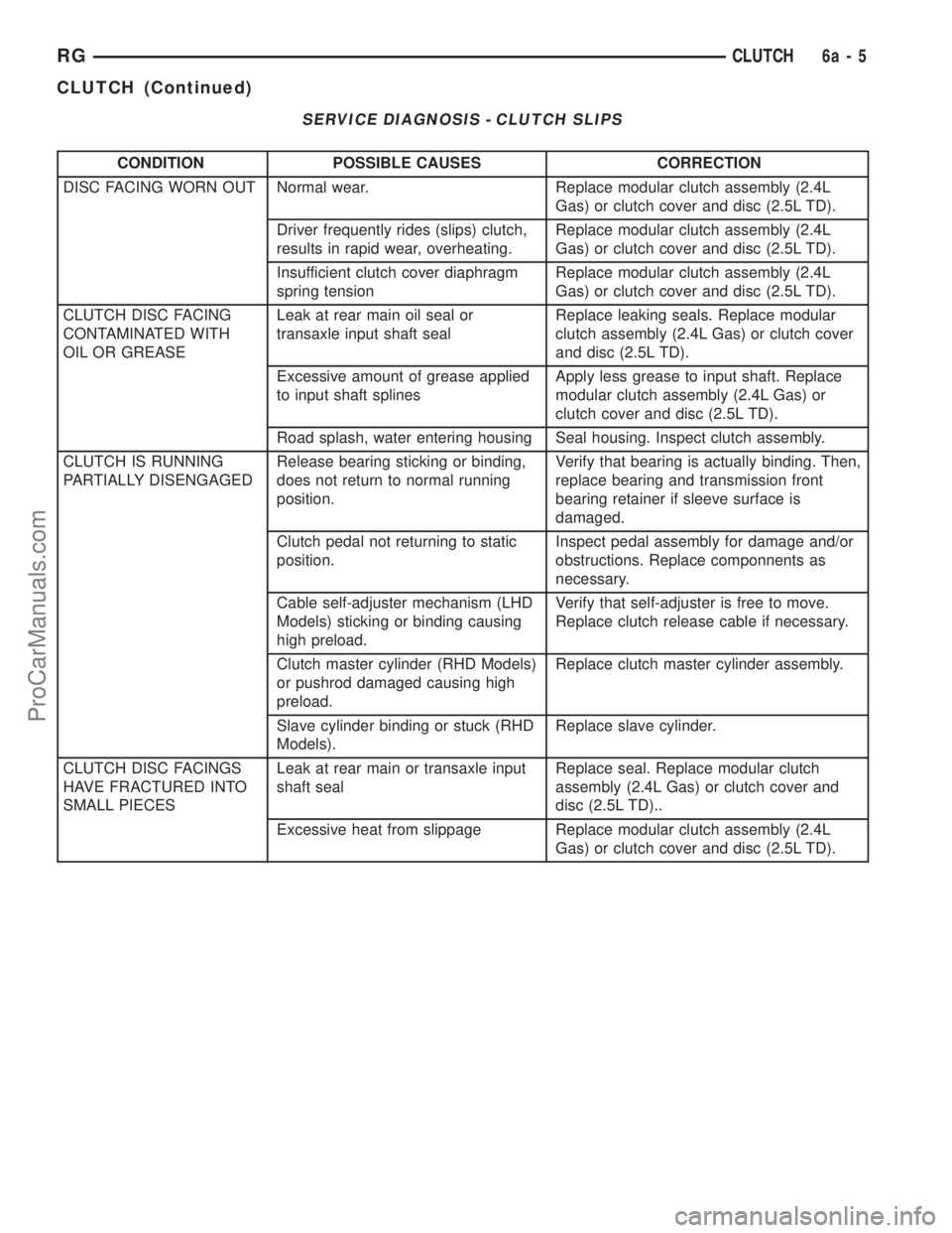
SERVICE DIAGNOSIS - CLUTCH SLIPS
CONDITION POSSIBLE CAUSES CORRECTION
DISC FACING WORN OUT Normal wear. Replace modular clutch assembly (2.4L
Gas) or clutch cover and disc (2.5L TD).
Driver frequently rides (slips) clutch,
results in rapid wear, overheating.Replace modular clutch assembly (2.4L
Gas) or clutch cover and disc (2.5L TD).
Insufficient clutch cover diaphragm
spring tensionReplace modular clutch assembly (2.4L
Gas) or clutch cover and disc (2.5L TD).
CLUTCH DISC FACING
CONTAMINATED WITH
OIL OR GREASELeak at rear main oil seal or
transaxle input shaft sealReplace leaking seals. Replace modular
clutch assembly (2.4L Gas) or clutch cover
and disc (2.5L TD).
Excessive amount of grease applied
to input shaft splinesApply less grease to input shaft. Replace
modular clutch assembly (2.4L Gas) or
clutch cover and disc (2.5L TD).
Road splash, water entering housing Seal housing. Inspect clutch assembly.
CLUTCH IS RUNNING
PARTIALLY DISENGAGEDRelease bearing sticking or binding,
does not return to normal running
position.Verify that bearing is actually binding. Then,
replace bearing and transmission front
bearing retainer if sleeve surface is
damaged.
Clutch pedal not returning to static
position.Inspect pedal assembly for damage and/or
obstructions. Replace componnents as
necessary.
Cable self-adjuster mechanism (LHD
Models) sticking or binding causing
high preload.Verify that self-adjuster is free to move.
Replace clutch release cable if necessary.
Clutch master cylinder (RHD Models)
or pushrod damaged causing high
preload.Replace clutch master cylinder assembly.
Slave cylinder binding or stuck (RHD
Models).Replace slave cylinder.
CLUTCH DISC FACINGS
HAVE FRACTURED INTO
SMALL PIECESLeak at rear main or transaxle input
shaft sealReplace seal. Replace modular clutch
assembly (2.4L Gas) or clutch cover and
disc (2.5L TD)..
Excessive heat from slippage Replace modular clutch assembly (2.4L
Gas) or clutch cover and disc (2.5L TD).
RGCLUTCH6a-5
CLUTCH (Continued)
ProCarManuals.com
Page 257 of 2321
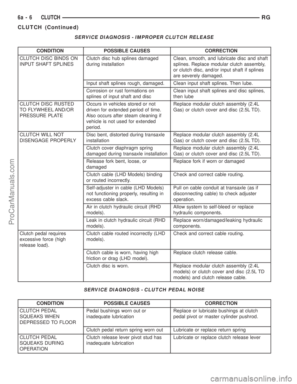
SERVICE DIAGNOSIS - IMPROPER CLUTCH RELEASE
CONDITION POSSIBLE CAUSES CORRECTION
CLUTCH DISC BINDS ON
INPUT SHAFT SPLINESClutch disc hub splines damaged
during installationClean, smooth, and lubricate disc and shaft
splines. Replace modular clutch assembly,
or clutch disc, and/or input shaft if splines
are severely damaged.
Input shaft splines rough, damaged. Clean input shaft splines. Then lube.
Corrosion or rust formations on
splines of input shaft and discClean input shaft splines and disc splines,
then lube
CLUTCH DISC RUSTED
TO FLYWHEEL AND/OR
PRESSURE PLATEOccurs in vehicles stored or not
driven for extended period of time.
Also occurs after steam cleaning if
vehicle is not used for extended
period.Replace modular clutch assembly (2.4L
Gas) or clutch cover and disc (2.5L TD).
CLUTCH WILL NOT
DISENGAGE PROPERLYDisc bent, distorted during transaxle
installationReplace modular clutch assembly (2.4L
Gas) or clutch cover and disc (2.5L TD).
Clutch cover diaphragm spring
damaged during transaxle installationReplace modular clutch assembly (2.4L
Gas) or clutch cover and disc (2.5L TD).
Release fork bent, loose, or
damagedReplace fork if worn or damaged
Clutch cable (LHD Models) binding
or routed incorrectly.Check and correct cable routing.
Self-adjuster in cable (LHD Models)
not functioning properly, resulting in
excess cable slack.Pull on cable conduit at transaxle (as if
disconnecting cable) to check adjuster
operation.
Air in clutch hydraulic circuit (RHD
models).Allow system to self-bleed or replace
hydraulic components.
Leak in clutch hydraulic circuit (RHD
models).Replace worn/damaged/leaking hydraulic
components.
Clutch pedal requires
excessive force (high
release load).Clutch cable routed incorrectly (LHD
models).Check and correct cable routing.
Clutch cable is worn, having high
friction or drag (LHD model).Replace clutch release cable.
Clutch disc is worn. Replace modular clutch assembly (2.4L
models) or clutch cover and disc (2.5L TD
models) and clutch release cable.
SERVICE DIAGNOSIS - CLUTCH PEDAL NOISE
CONDITION POSSIBLE CAUSES CORRECTION
CLUTCH PEDAL
SQUEAKS WHEN
DEPRESSED TO FLOORPedal bushings worn out or
inadequate lubricationReplace or lubricate bushings at clutch
pedal pivot or master cylinder pushrod.
Clutch pedal return spring worn out Lubricate or replace return spring
CLUTCH PEDAL
SQUEAKS DURING
OPERATIONClutch release lever pivot stud has
inadequate lubricationLubricate or replace clutch release lever
6a - 6 CLUTCHRG
CLUTCH (Continued)
ProCarManuals.com
Page 258 of 2321
DIAGNOSIS AND TESTING - DRIVE PLATE
MISALIGNMENT
Common causes of misalignment are:
²Heat warping
²Mounting drive plate on a dirty crankshaft
flange
²Incorrect bolt tightening
²Improper seating on the crankshaft shoulder
²Loose crankshaft bolts
Clean the crankshaft flange before mounting the
drive plate. Dirt and grease on the flange surface
may misalign the flywheel, causing excessive runout.
Use new bolts when mounting drive plate to crank-
shaft. Tighten drive plate bolts to specified torque
only. Over-tightening can distort the drive plate hub
causing excessive runout.
DIAGNOSIS AND TESTING - CLUTCH COVER
AND DISC RUNOUT
Check condition of the clutch cover before installa-
tion. A warped cover or diaphragm spring will cause
grab and/or incomplete release or engagement. Use
care when handling the clutch assembly. Impact can
distort the cover, diaphragm spring, and release fin-
gers.
DIAGNOSIS AND TESTING - CLUTCH CHATTER
COMPLAINTS
For all clutch chatter complaints, perform the fol-
lowing:
(1) Check for loose, misaligned, or broken engine
and transmission mounts. If present, they should be
corrected at this time. Test vehicle for chatter. If
chatter is gone, there is no need to go any further.
(2) If chatter persists, check hydraulic clutch
release system is functioning properly.
(3) Check for loose connections in drivetrain. Cor-
rect any problems and determine if clutch chatter
complaints have been satisfied. If not:
(a) Remove transaxle.
(b) Check to see if the release bearing is sticky
or binding. Replace bearing, if needed.
(c) Check linkage for excessive wear on the pivot
stud and fork fingers. Replace all worn parts.
(d) Check clutch assembly for contamination
(dirt, oil). Replace clutch assembly, if required.
(e) Check to see if the clutch disc hub splines
are damaged. Replace with new clutch assembly, if
necessary.
(f) Check input shaft splines for damage.
Replace, if necessary.
(g) Check for uneven wear on clutch fingers.
(h) Check for broken clutch cover diaphragm
spring fingers. Replace with new clutch assembly,
if necessary.
SPECIAL TOOLS
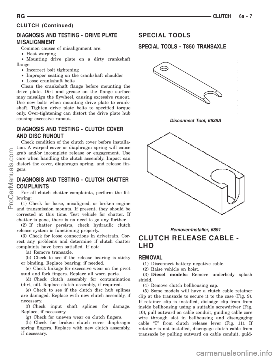
SPECIAL TOOLS - T850 TRANSAXLE
CLUTCH RELEASE CABLE -
LHD
REMOVAL
(1) Disconnect battery negative cable.
(2) Raise vehicle on hoist.
(3)Diesel models:Remove underbody splash
shield.
(4) Remove clutch bellhousing cap.
(5) Some models will have a clutch cable retainer
clip at the transaxle to secure it to the case (Fig. 9).
If retainer clip is installed, dislodge clip from from
inside bellhousing using a suitable screwdriver (Fig.
10), pull outward on cable conduit, guiding cable core
wire through slot in bellhousing and disengaging
cable ªTº from clutch release lever (Fig. 11). If
retainer is not installed, disengage clutch cable from
transaxle by pulling outward on cable conduit, guid-
Disconnect Tool, 6638A
Remover/Installer, 6891
RGCLUTCH6a-7
CLUTCH (Continued)
ProCarManuals.com
Page 259 of 2321
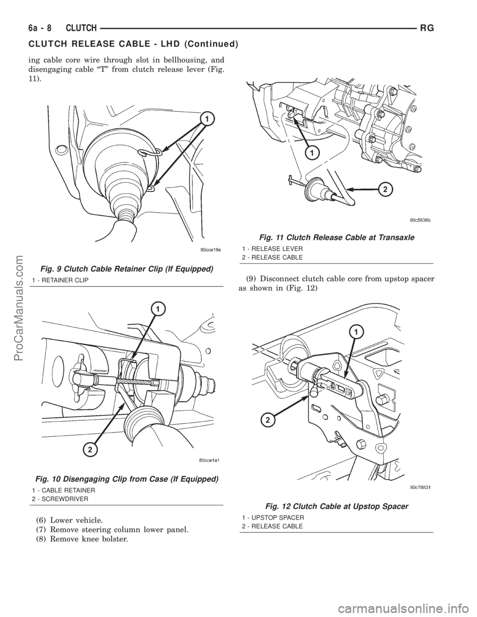
ing cable core wire through slot in bellhousing, and
disengaging cable ªTº from clutch release lever (Fig.
11).
(6) Lower vehicle.
(7) Remove steering column lower panel.
(8) Remove knee bolster.(9) Disconnect clutch cable core from upstop spacer
as shown in (Fig. 12)
Fig. 9 Clutch Cable Retainer Clip (If Equipped)
1 - RETAINER CLIP
Fig. 10 Disengaging Clip from Case (If Equipped)
1 - CABLE RETAINER
2 - SCREWDRIVER
Fig. 11 Clutch Release Cable at Transaxle
1 - RELEASE LEVER
2 - RELEASE CABLE
Fig. 12 Clutch Cable at Upstop Spacer
1 - UPSTOP SPACER
2 - RELEASE CABLE
6a - 8 CLUTCHRG
CLUTCH RELEASE CABLE - LHD (Continued)
ProCarManuals.com
Page 260 of 2321
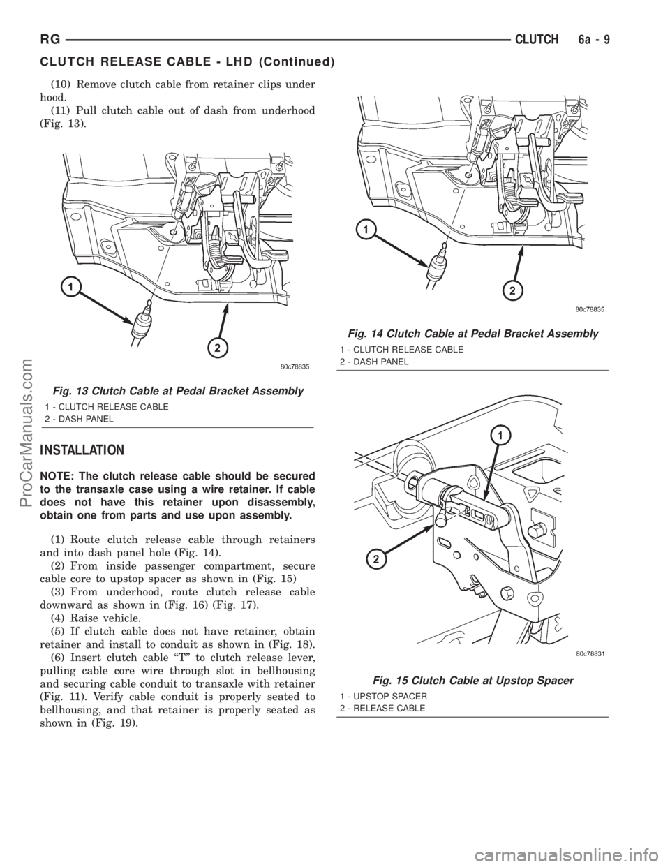
(10) Remove clutch cable from retainer clips under
hood.
(11) Pull clutch cable out of dash from underhood
(Fig. 13).
INSTALLATION
NOTE: The clutch release cable should be secured
to the transaxle case using a wire retainer. If cable
does not have this retainer upon disassembly,
obtain one from parts and use upon assembly.
(1) Route clutch release cable through retainers
and into dash panel hole (Fig. 14).
(2) From inside passenger compartment, secure
cable core to upstop spacer as shown in (Fig. 15)
(3) From underhood, route clutch release cable
downward as shown in (Fig. 16) (Fig. 17).
(4) Raise vehicle.
(5) If clutch cable does not have retainer, obtain
retainer and install to conduit as shown in (Fig. 18).
(6) Insert clutch cable ªTº to clutch release lever,
pulling cable core wire through slot in bellhousing
and securing cable conduit to transaxle with retainer
(Fig. 11). Verify cable conduit is properly seated to
bellhousing, and that retainer is properly seated as
shown in (Fig. 19).
Fig. 13 Clutch Cable at Pedal Bracket Assembly
1 - CLUTCH RELEASE CABLE
2 - DASH PANEL
Fig. 14 Clutch Cable at Pedal Bracket Assembly
1 - CLUTCH RELEASE CABLE
2 - DASH PANEL
Fig. 15 Clutch Cable at Upstop Spacer
1 - UPSTOP SPACER
2 - RELEASE CABLE
RGCLUTCH6a-9
CLUTCH RELEASE CABLE - LHD (Continued)
ProCarManuals.com