DODGE TOWN AND COUNTRY 2004 Service Manual
Manufacturer: DODGE, Model Year: 2004, Model line: TOWN AND COUNTRY, Model: DODGE TOWN AND COUNTRY 2004Pages: 2585, PDF Size: 62.54 MB
Page 1901 of 2585
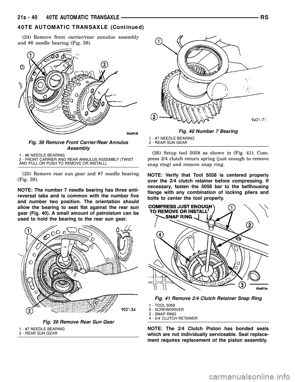
(24) Remove front carrier/rear annulus assembly
and #6 needle bearing (Fig. 38).
(25) Remove rear sun gear and #7 needle bearing
(Fig. 39).
NOTE: The number 7 needle bearing has three anti-
reversal tabs and is common with the number five
and number two position. The orientation should
allow the bearing to seat flat against the rear sun
gear (Fig. 40). A small amount of petrolatum can be
used to hold the bearing to the rear sun gear. (26) Setup tool 5058 as shown in (Fig. 41). Com-
press 2/4 clutch return spring (just enough to remove
snap ring) and remove snap ring.
NOTE: Verify that Tool 5058 is centered properly
over the 2/4 clutch retainer before compressing. If
necessary, fasten the 5058 bar to the bellhousing
flange with any combination of locking pliers and
bolts to center the tool properly.
NOTE: The 2/4 Clutch Piston has bonded seals
which are not individually serviceable. Seal replace-
ment requires replacement of the piston assembly.
Fig. 38 Remove Front Carrier/Rear Annulus Assembly
1 - #6 NEEDLE BEARING
2 - FRONT CARRIER AND REAR ANNULUS ASSEMBLY (TWIST
AND PULL OR PUSH TO REMOVE OR INSTALL).
Fig. 39 Remove Rear Sun Gear
1 - #7 NEEDLE BEARING
2 - REAR SUN GEAR
Fig. 40 Number 7 Bearing
1 - #7 NEEDLE BEARING
2 - REAR SUN GEAR
Fig. 41 Remove 2/4 Clutch Retainer Snap Ring
1 - TOOL 5058
2 - SCREWDRIVER
3 - SNAP RING
4 - 2/4 CLUTCH RETAINER
21s - 40 40TE AUTOMATIC TRANSAXLERS
40TE AUTOMATIC TRANSAXLE (Continued)
Page 1902 of 2585
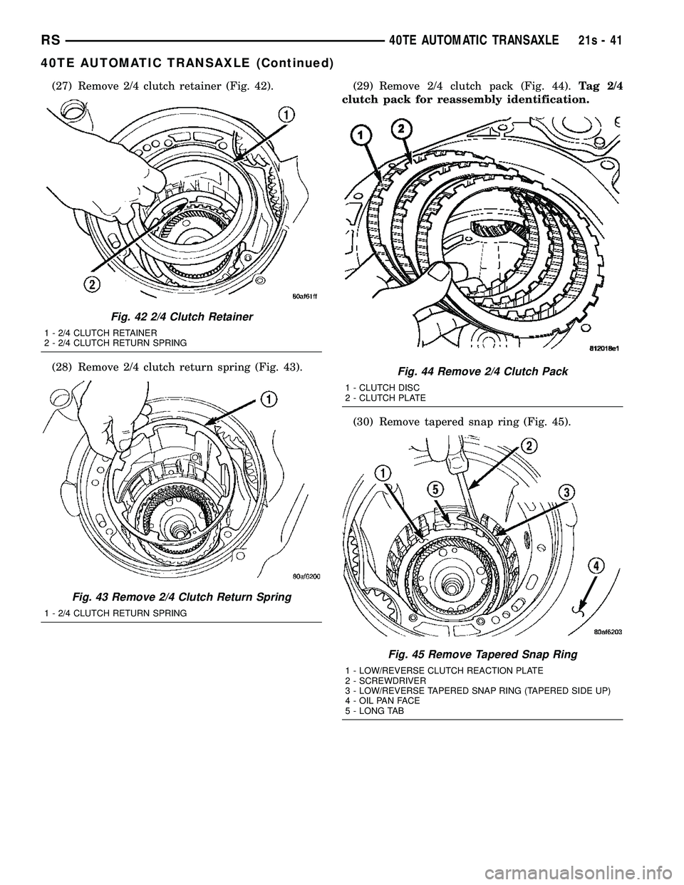
(27) Remove 2/4 clutch retainer (Fig. 42).
(28) Remove 2/4 clutch return spring (Fig. 43).(29) Remove 2/4 clutch pack (Fig. 44).
Tag 2/4
clutch pack for reassembly identification.
(30) Remove tapered snap ring (Fig. 45).
Fig. 42 2/4 Clutch Retainer
1 - 2/4 CLUTCH RETAINER
2 - 2/4 CLUTCH RETURN SPRING
Fig. 43 Remove 2/4 Clutch Return Spring
1 - 2/4 CLUTCH RETURN SPRING
Fig. 44 Remove 2/4 Clutch Pack
1 - CLUTCH DISC
2 - CLUTCH PLATE
Fig. 45 Remove Tapered Snap Ring
1 - LOW/REVERSE CLUTCH REACTION PLATE
2 - SCREWDRIVER
3 - LOW/REVERSE TAPERED SNAP RING (TAPERED SIDE UP)
4 - OIL PAN FACE
5 - LONG TAB
RS 40TE AUTOMATIC TRANSAXLE21s-41
40TE AUTOMATIC TRANSAXLE (Continued)
Page 1903 of 2585
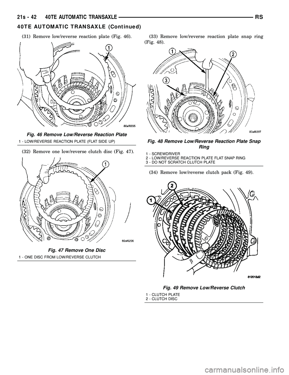
(31) Remove low/reverse reaction plate (Fig. 46).
(32) Remove one low/reverse clutch disc (Fig. 47).(33) Remove low/reverse reaction plate snap ring
(Fig. 48).
(34) Remove low/reverse clutch pack (Fig. 49).
Fig. 46 Remove Low/Reverse Reaction Plate
1 - LOW/REVERSE REACTION PLATE (FLAT SIDE UP)
Fig. 47 Remove One Disc
1 - ONE DISC FROM LOW/REVERSE CLUTCH
Fig. 48 Remove Low/Reverse Reaction Plate Snap Ring
1 - SCREWDRIVER
2 - LOW/REVERSE REACTION PLATE FLAT SNAP RING
3 - DO NOT SCRATCH CLUTCH PLATE
Fig. 49 Remove Low/Reverse Clutch
1 - CLUTCH PLATE
2 - CLUTCH DISC
21s - 42 40TE AUTOMATIC TRANSAXLERS
40TE AUTOMATIC TRANSAXLE (Continued)
Page 1904 of 2585
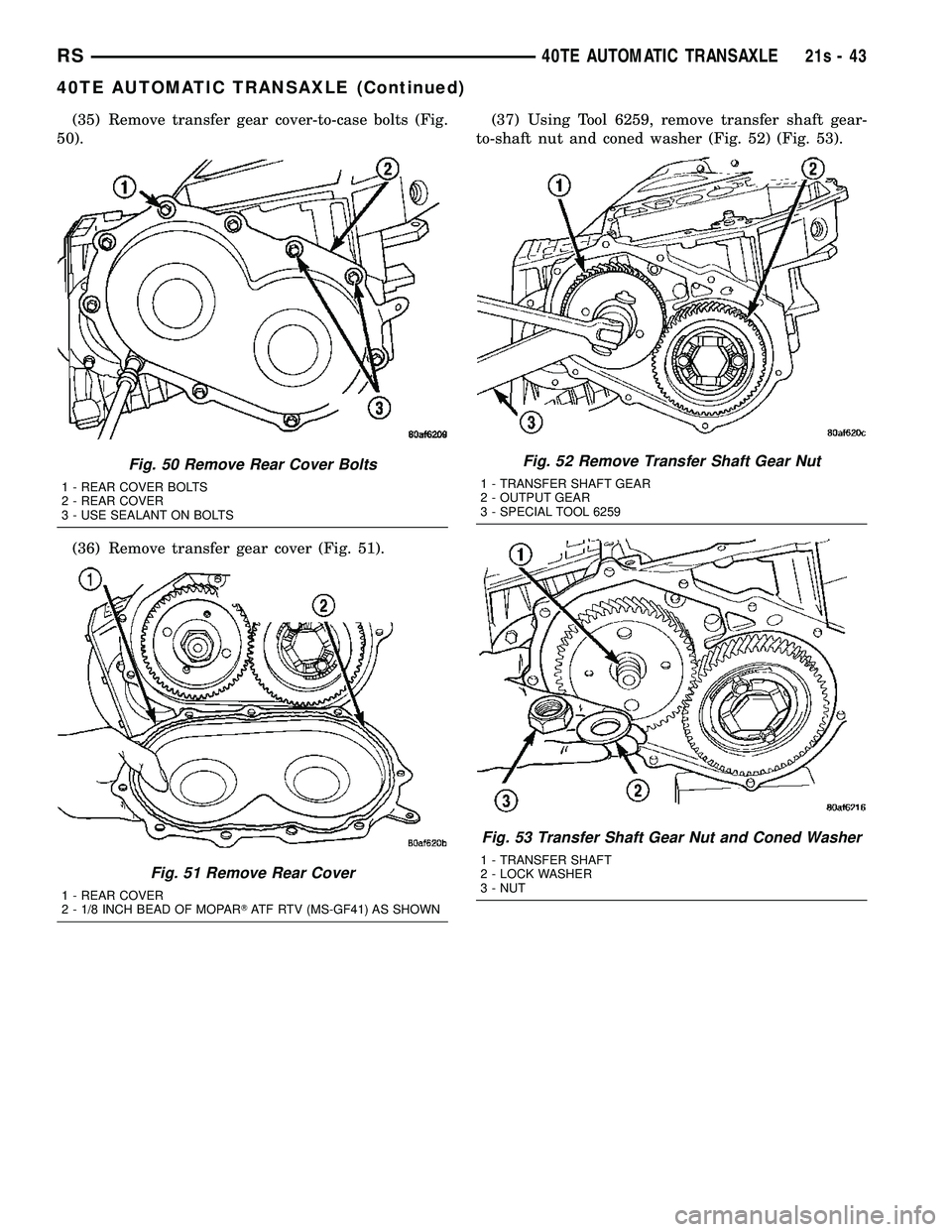
(35) Remove transfer gear cover-to-case bolts (Fig.
50).
(36) Remove transfer gear cover (Fig. 51). (37) Using Tool 6259, remove transfer shaft gear-
to-shaft nut and coned washer (Fig. 52) (Fig. 53).
Fig. 50 Remove Rear Cover Bolts
1 - REAR COVER BOLTS
2 - REAR COVER
3 - USE SEALANT ON BOLTS
Fig. 51 Remove Rear Cover
1 - REAR COVER
2 - 1/8 INCH BEAD OF MOPAR TATF RTV (MS-GF41) AS SHOWN
Fig. 52 Remove Transfer Shaft Gear Nut
1 - TRANSFER SHAFT GEAR
2 - OUTPUT GEAR
3 - SPECIAL TOOL 6259
Fig. 53 Transfer Shaft Gear Nut and Coned Washer
1 - TRANSFER SHAFT
2 - LOCK WASHER
3 - NUT
RS 40TE AUTOMATIC TRANSAXLE21s-43
40TE AUTOMATIC TRANSAXLE (Continued)
Page 1905 of 2585
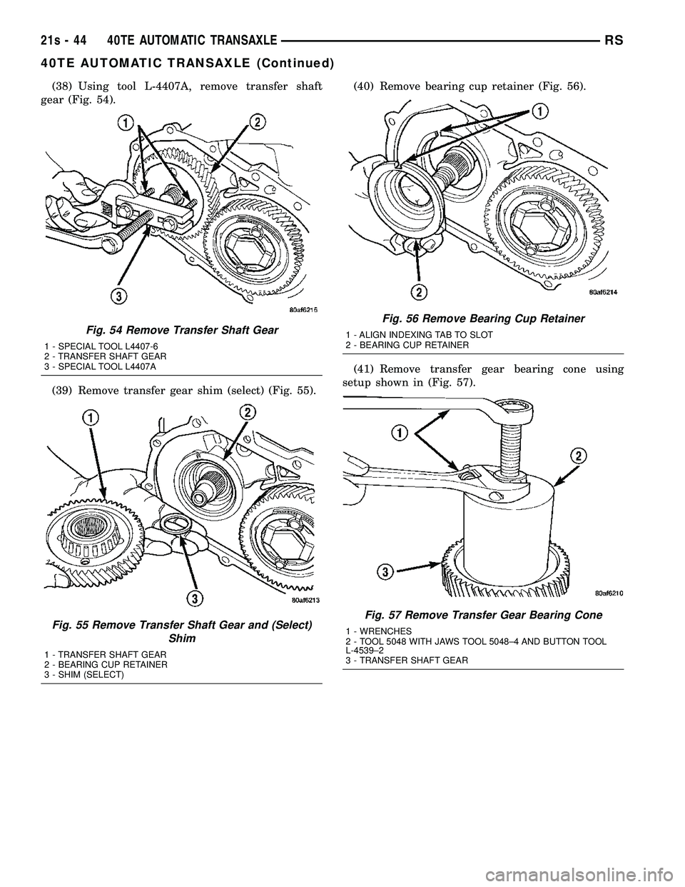
(38) Using tool L-4407A, remove transfer shaft
gear (Fig. 54).
(39) Remove transfer gear shim (select) (Fig. 55). (40) Remove bearing cup retainer (Fig. 56).
(41) Remove transfer gear bearing cone using
setup shown in (Fig. 57).
Fig. 54 Remove Transfer Shaft Gear
1 - SPECIAL TOOL L4407-6
2 - TRANSFER SHAFT GEAR
3 - SPECIAL TOOL L4407A
Fig. 55 Remove Transfer Shaft Gear and (Select) Shim
1 - TRANSFER SHAFT GEAR
2 - BEARING CUP RETAINER
3 - SHIM (SELECT)
Fig. 56 Remove Bearing Cup Retainer
1 - ALIGN INDEXING TAB TO SLOT
2 - BEARING CUP RETAINER
Fig. 57 Remove Transfer Gear Bearing Cone
1 - WRENCHES
2 - TOOL 5048 WITH JAWS TOOL 5048±4 AND BUTTON TOOL
L-4539±2
3 - TRANSFER SHAFT GEAR
21s - 44 40TE AUTOMATIC TRANSAXLERS
40TE AUTOMATIC TRANSAXLE (Continued)
Page 1906 of 2585
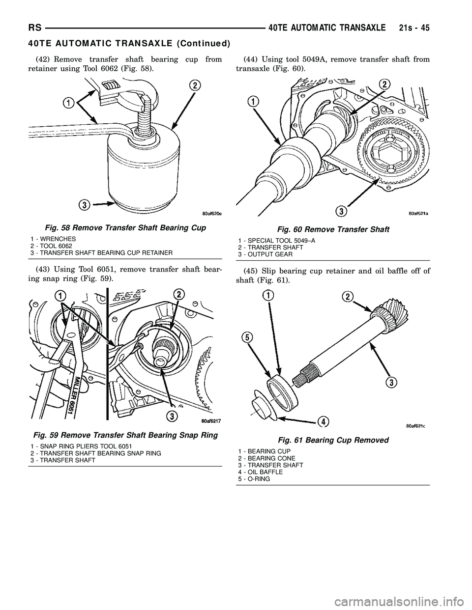
(42) Remove transfer shaft bearing cup from
retainer using Tool 6062 (Fig. 58).
(43) Using Tool 6051, remove transfer shaft bear-
ing snap ring (Fig. 59). (44) Using tool 5049A, remove transfer shaft from
transaxle (Fig. 60).
(45) Slip bearing cup retainer and oil baffle off of
shaft (Fig. 61).
Fig. 58 Remove Transfer Shaft Bearing Cup
1 - WRENCHES
2 - TOOL 6062
3 - TRANSFER SHAFT BEARING CUP RETAINER
Fig. 59 Remove Transfer Shaft Bearing Snap Ring
1 - SNAP RING PLIERS TOOL 6051
2 - TRANSFER SHAFT BEARING SNAP RING
3 - TRANSFER SHAFT
Fig. 60 Remove Transfer Shaft
1 - SPECIAL TOOL 5049±A
2 - TRANSFER SHAFT
3 - OUTPUT GEAR
Fig. 61 Bearing Cup Removed
1 - BEARING CUP
2 - BEARING CONE
3 - TRANSFER SHAFT
4 - OIL BAFFLE
5 - O-RING
RS 40TE AUTOMATIC TRANSAXLE21s-45
40TE AUTOMATIC TRANSAXLE (Continued)
Page 1907 of 2585
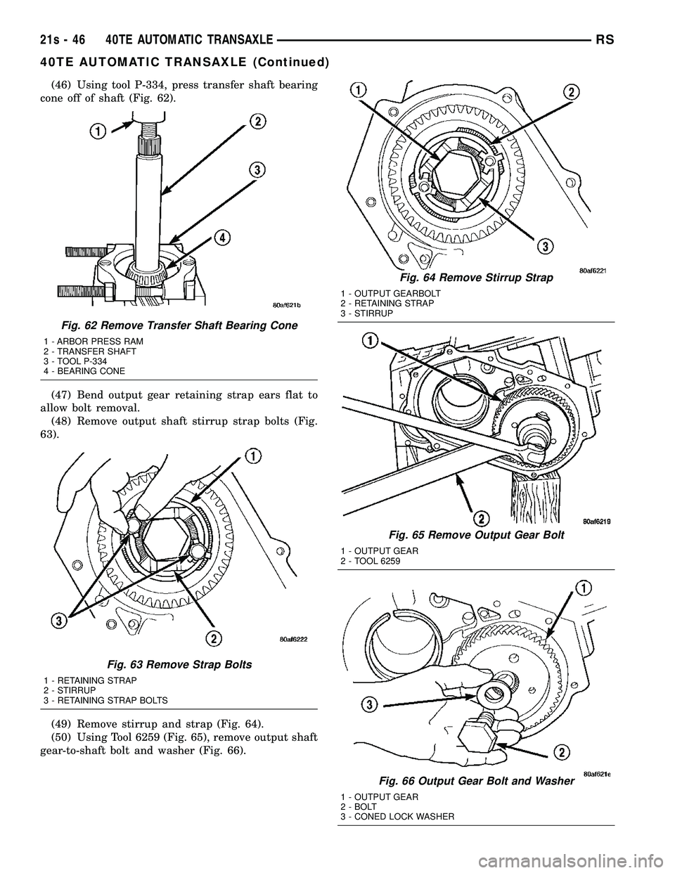
(46) Using tool P-334, press transfer shaft bearing
cone off of shaft (Fig. 62).
(47) Bend output gear retaining strap ears flat to
allow bolt removal. (48) Remove output shaft stirrup strap bolts (Fig.
63).
(49) Remove stirrup and strap (Fig. 64).
(50) Using Tool 6259 (Fig. 65), remove output shaft
gear-to-shaft bolt and washer (Fig. 66).
Fig. 62 Remove Transfer Shaft Bearing Cone
1 - ARBOR PRESS RAM
2 - TRANSFER SHAFT
3 - TOOL P-334
4 - BEARING CONE
Fig. 63 Remove Strap Bolts
1 - RETAINING STRAP
2 - STIRRUP
3 - RETAINING STRAP BOLTS
Fig. 64 Remove Stirrup Strap
1 - OUTPUT GEARBOLT
2 - RETAINING STRAP
3 - STIRRUP
Fig. 65 Remove Output Gear Bolt
1 - OUTPUT GEAR
2 - TOOL 6259
Fig. 66 Output Gear Bolt and Washer
1 - OUTPUT GEAR
2 - BOLT
3 - CONED LOCK WASHER
21s - 46 40TE AUTOMATIC TRANSAXLERS
40TE AUTOMATIC TRANSAXLE (Continued)
Page 1908 of 2585
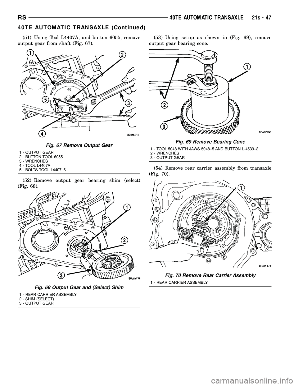
(51) Using Tool L4407A, and button 6055, remove
output gear from shaft (Fig. 67).
(52) Remove output gear bearing shim (select)
(Fig. 68). (53) Using setup as shown in (Fig. 69), remove
output gear bearing cone.
(54) Remove rear carrier assembly from transaxle
(Fig. 70).
Fig. 67 Remove Output Gear
1 - OUTPUT GEAR
2 - BUTTON TOOL 6055
3 - WRENCHES
4 - TOOL L4407A
5 - BOLTS TOOL L4407±6
Fig. 68 Output Gear and (Select) Shim
1 - REAR CARRIER ASSEMBLY
2 - SHIM (SELECT)
3 - OUTPUT GEAR
Fig. 69 Remove Bearing Cone
1 - TOOL 5048 WITH JAWS 5048±5 AND BUTTON L-4539±2
2 - WRENCHES
3 - OUTPUT GEAR
Fig. 70 Remove Rear Carrier Assembly
1 - REAR CARRIER ASSEMBLY
RS 40TE AUTOMATIC TRANSAXLE21s-47
40TE AUTOMATIC TRANSAXLE (Continued)
Page 1909 of 2585
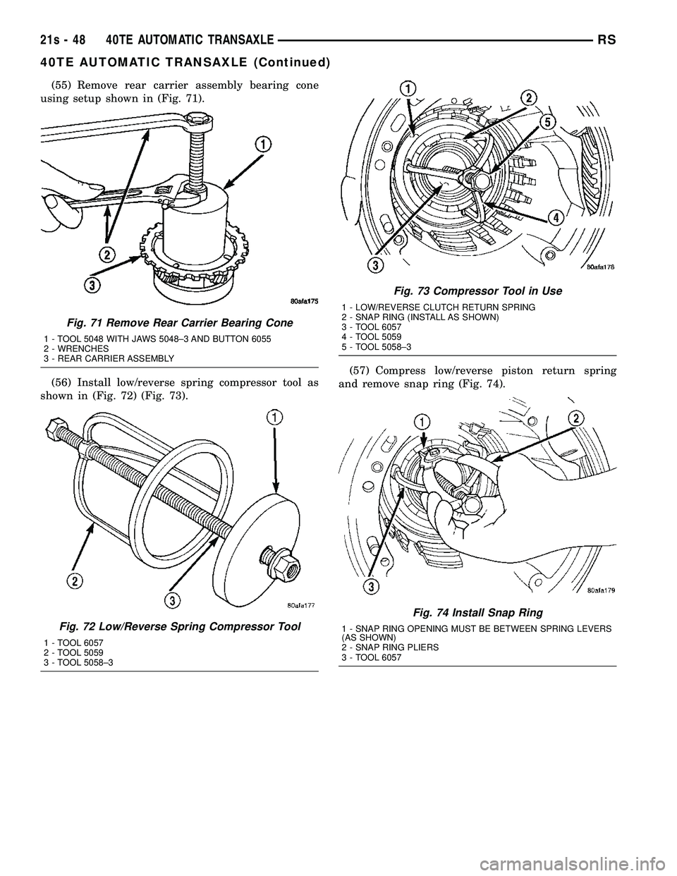
(55) Remove rear carrier assembly bearing cone
using setup shown in (Fig. 71).
(56) Install low/reverse spring compressor tool as
shown in (Fig. 72) (Fig. 73). (57) Compress low/reverse piston return spring
and remove snap ring (Fig. 74).
Fig. 71 Remove Rear Carrier Bearing Cone
1 - TOOL 5048 WITH JAWS 5048±3 AND BUTTON 6055
2 - WRENCHES
3 - REAR CARRIER ASSEMBLY
Fig. 72 Low/Reverse Spring Compressor Tool
1 - TOOL 6057
2 - TOOL 5059
3 - TOOL 5058±3
Fig. 73 Compressor Tool in Use
1 - LOW/REVERSE CLUTCH RETURN SPRING
2 - SNAP RING (INSTALL AS SHOWN)
3 - TOOL 6057
4 - TOOL 5059
5 - TOOL 5058±3
Fig. 74 Install Snap Ring
1 - SNAP RING OPENING MUST BE BETWEEN SPRING LEVERS
(AS SHOWN)
2 - SNAP RING PLIERS
3 - TOOL 6057
21s - 48 40TE AUTOMATIC TRANSAXLERS
40TE AUTOMATIC TRANSAXLE (Continued)
Page 1910 of 2585
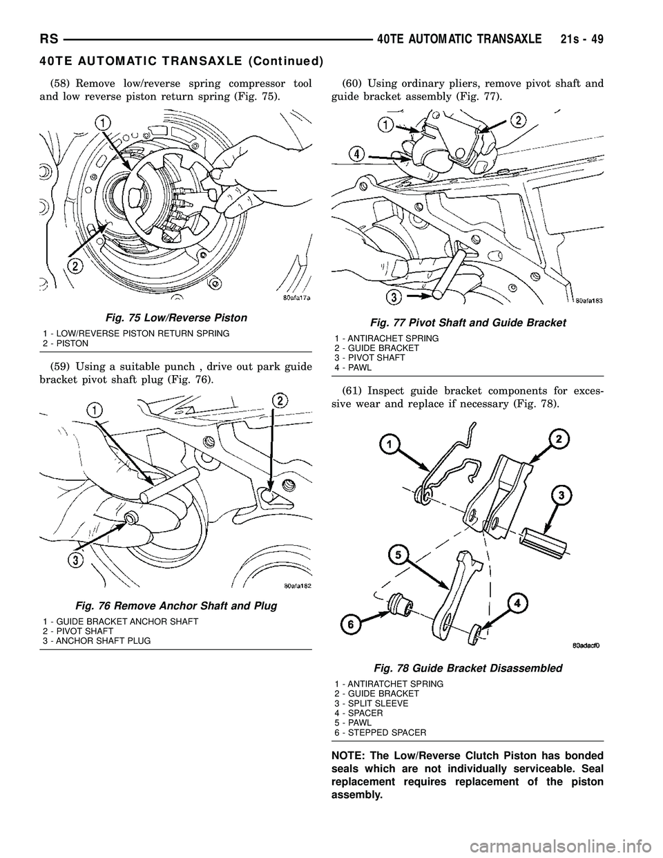
(58) Remove low/reverse spring compressor tool
and low reverse piston return spring (Fig. 75).
(59) Using a suitable punch , drive out park guide
bracket pivot shaft plug (Fig. 76). (60) Using ordinary pliers, remove pivot shaft and
guide bracket assembly (Fig. 77).
(61) Inspect guide bracket components for exces-
sive wear and replace if necessary (Fig. 78).
NOTE: The Low/Reverse Clutch Piston has bonded
seals which are not individually serviceable. Seal
replacement requires replacement of the piston
assembly.
Fig. 75 Low/Reverse Piston
1 - LOW/REVERSE PISTON RETURN SPRING
2 - PISTON
Fig. 76 Remove Anchor Shaft and Plug
1 - GUIDE BRACKET ANCHOR SHAFT
2 - PIVOT SHAFT
3 - ANCHOR SHAFT PLUG
Fig. 77 Pivot Shaft and Guide Bracket
1 - ANTIRACHET SPRING
2 - GUIDE BRACKET
3 - PIVOT SHAFT
4-PAWL
Fig. 78 Guide Bracket Disassembled
1 - ANTIRATCHET SPRING
2 - GUIDE BRACKET
3 - SPLIT SLEEVE
4 - SPACER
5-PAWL
6 - STEPPED SPACER
RS 40TE AUTOMATIC TRANSAXLE21s-49
40TE AUTOMATIC TRANSAXLE (Continued)