DODGE TOWN AND COUNTRY 2004 Service Manual
TOWN AND COUNTRY 2004
DODGE
DODGE
https://www.carmanualsonline.info/img/12/56919/w960_56919-0.png
DODGE TOWN AND COUNTRY 2004 Service Manual
Trending: maintenance schedule, spark plugs, key fob, jump start, fuses, battery location, water pump
Page 1861 of 2585
Page 1862 of 2585
TRANSMISSION/TRANSAXLE
TABLE OF CONTENTS
page page
T850 MANUAL TRANSAXLE ................1
40TE AUTOMATIC TRANSAXLE .............2441TE AUTOMATIC TRANSAXLE
............166
T850 MANUAL TRANSAXLE
TABLE OF CONTENTS
page page
INPUT SHAFT DESCRIPTION ..........................1
DISASSEMBLY ..........................1
ASSEMBLY .............................5 INTERMEDIATE SHAFT
DESCRIPTION ..........................9
DISASSEMBLY .........................10
ASSEMBLY ............................17
INPUT SHAFT
DESCRIPTION
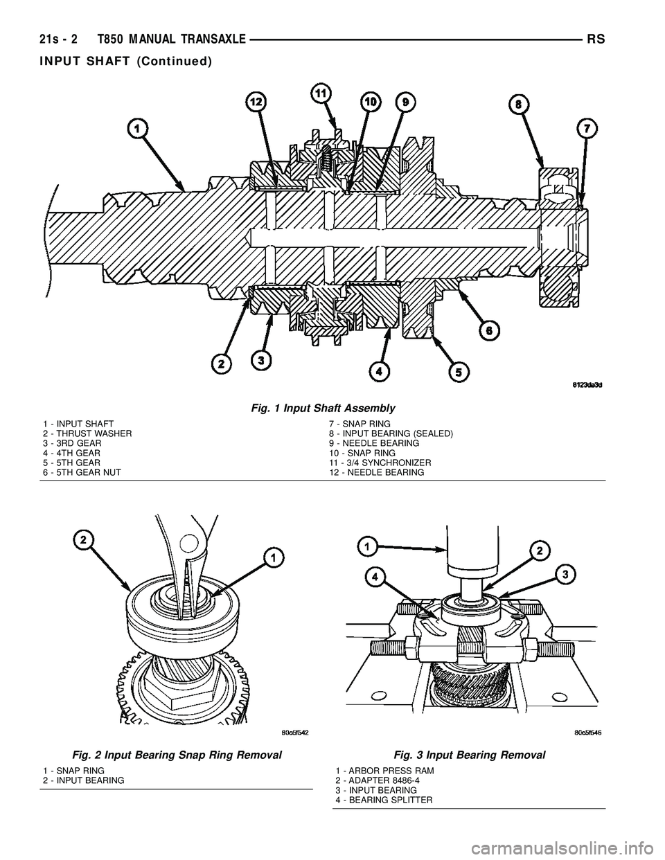
The input shaft assembly (Fig. 1) is part of the
transaxle geartrain, is driven by the clutch assembly,
and consists of the following components: ² Input Mainshaft
² 3rd Speed Gear
² 4th Speed Gear
² 3/4 Synchronizer
² 5th Input Gear
The input shaft meshes with the intermediate
shaft, and is supported by a needle bearing at the
front of the transaxle, and a sealed roller bearing at
the rear of the transaxle.
DISASSEMBLY
NOTE: When servicing the input shaft assembly, all
snap rings which are removed MUST be replaced
with new snap rings upon reassembly. The 5th gear
nut must be replaced also.
(1) Invert input shaft assembly and place in fix-
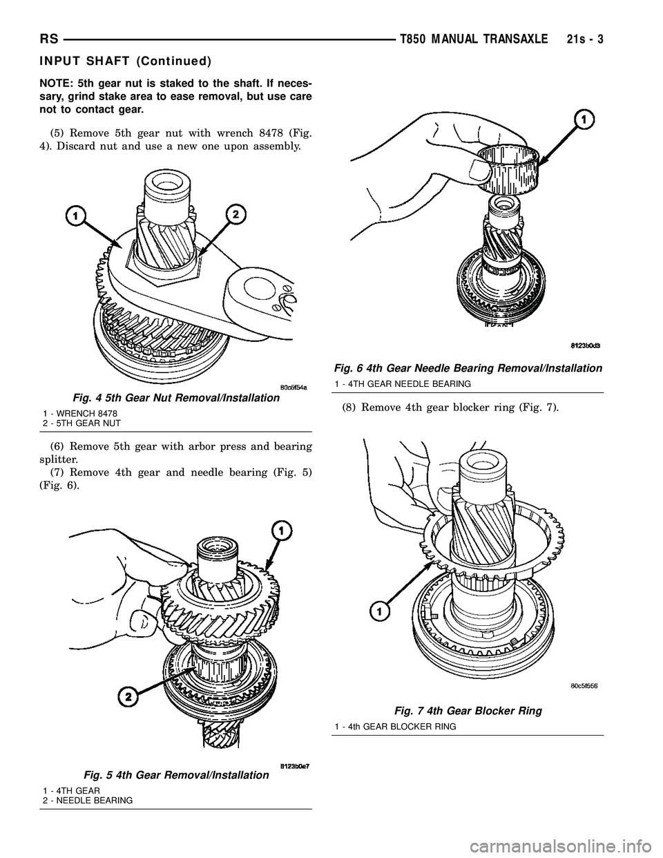
ture 8487. (2) Remove input bearing snap ring (Fig. 2).
(3) Remove input bearing. Place input shaft
assembly onto arbor press table, with the input bear-
ing supported by bearing splitter (Fig. 3). Using
adapter 8486-4, press bearing off of shaft, while
helper supports shaft to prevent dropping. (4) Place input shaft assembly back into fixture
8487. Secure fixture to bench with fasteners, or
secure to bench vise.
RS TRANSMISSION/TRANSAXLE21s-1
Page 1863 of 2585
Fig. 1 Input Shaft Assembly
1 - INPUT SHAFT 7 - SNAP RING
2 - THRUST WASHER 8 - INPUT BEARING (SEALED)
3 - 3RD GEAR 9 - NEEDLE BEARING
4 - 4TH GEAR 10 - SNAP RING
5 - 5TH GEAR 11 - 3/4 SYNCHRONIZER
6 - 5TH GEAR NUT 12 - NEEDLE BEARING
Fig. 2 Input Bearing Snap Ring Removal
1 - SNAP RING
2 - INPUT BEARING
Fig. 3 Input Bearing Removal
1 - ARBOR PRESS RAM
2 - ADAPTER 8486-4
3 - INPUT BEARING
4 - BEARING SPLITTER
21s - 2 T850 MANUAL TRANSAXLERS
INPUT SHAFT (Continued)
Page 1864 of 2585
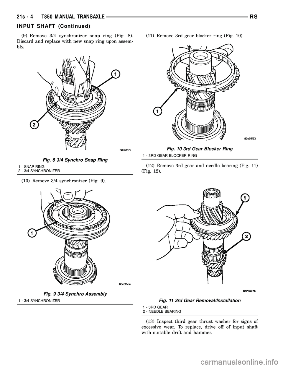
NOTE: 5th gear nut is staked to the shaft. If neces-
sary, grind stake area to ease removal, but use care
not to contact gear.(5) Remove 5th gear nut with wrench 8478 (Fig.
4). Discard nut and use a new one upon assembly.
(6) Remove 5th gear with arbor press and bearing
splitter. (7) Remove 4th gear and needle bearing (Fig. 5)
(Fig. 6). (8) Remove 4th gear blocker ring (Fig. 7).
Fig. 4 5th Gear Nut Removal/Installation
1 - WRENCH 8478
2 - 5TH GEAR NUT
Fig. 5 4th Gear Removal/Installation
1 - 4TH GEAR
2 - NEEDLE BEARING
Fig. 6 4th Gear Needle Bearing Removal/Installation
1 - 4TH GEAR NEEDLE BEARING
Fig. 7 4th Gear Blocker Ring
1 - 4th GEAR BLOCKER RING
RS
T850 MANUAL TRANSAXLE21s-3
INPUT SHAFT (Continued)
Page 1865 of 2585
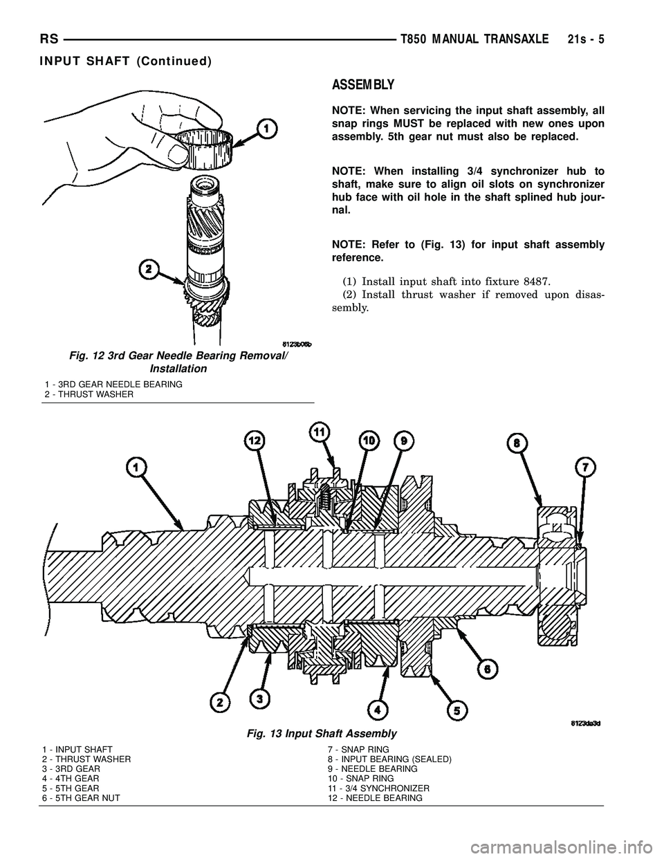
(9) Remove 3/4 synchronizer snap ring (Fig. 8).
Discard and replace with new snap ring upon assem-
bly.
(10) Remove 3/4 synchronizer (Fig. 9). (11) Remove 3rd gear blocker ring (Fig. 10).
(12) Remove 3rd gear and needle bearing (Fig. 11)
(Fig. 12).
(13) Inspect third gear thrust washer for signs of
excessive wear. To replace, drive off of input shaft
with suitable drift and hammer.
Fig. 8 3/4 Synchro Snap Ring
1 - SNAP RING
2 - 3/4 SYNCHRONIZER
Fig. 9 3/4 Synchro Assembly
1 - 3/4 SYNCHRONIZER
Fig. 10 3rd Gear Blocker Ring
1 - 3RD GEAR BLOCKER RING
Fig. 11 3rd Gear Removal/Installation
1 - 3RD GEAR
2 - NEEDLE BEARING
21s - 4 T850 MANUAL TRANSAXLERS
INPUT SHAFT (Continued)
Page 1866 of 2585
ASSEMBLY
NOTE: When servicing the input shaft assembly, all
snap rings MUST be replaced with new ones upon
assembly. 5th gear nut must also be replaced.
NOTE: When installing 3/4 synchronizer hub to
shaft, make sure to align oil slots on synchronizer
hub face with oil hole in the shaft splined hub jour-
nal.
NOTE: Refer to (Fig. 13) for input shaft assembly
reference.(1) Install input shaft into fixture 8487.
(2) Install thrust washer if removed upon disas-
sembly.
Fig. 12 3rd Gear Needle Bearing Removal/ Installation
1 - 3RD GEAR NEEDLE BEARING
2 - THRUST WASHER
Fig. 13 Input Shaft Assembly
1 - INPUT SHAFT 7 - SNAP RING
2 - THRUST WASHER 8 - INPUT BEARING (SEALED)
3 - 3RD GEAR 9 - NEEDLE BEARING
4 - 4TH GEAR 10 - SNAP RING
5 - 5TH GEAR 11 - 3/4 SYNCHRONIZER
6 - 5TH GEAR NUT 12 - NEEDLE BEARING
RS T850 MANUAL TRANSAXLE21s-5
INPUT SHAFT (Continued)
Page 1867 of 2585
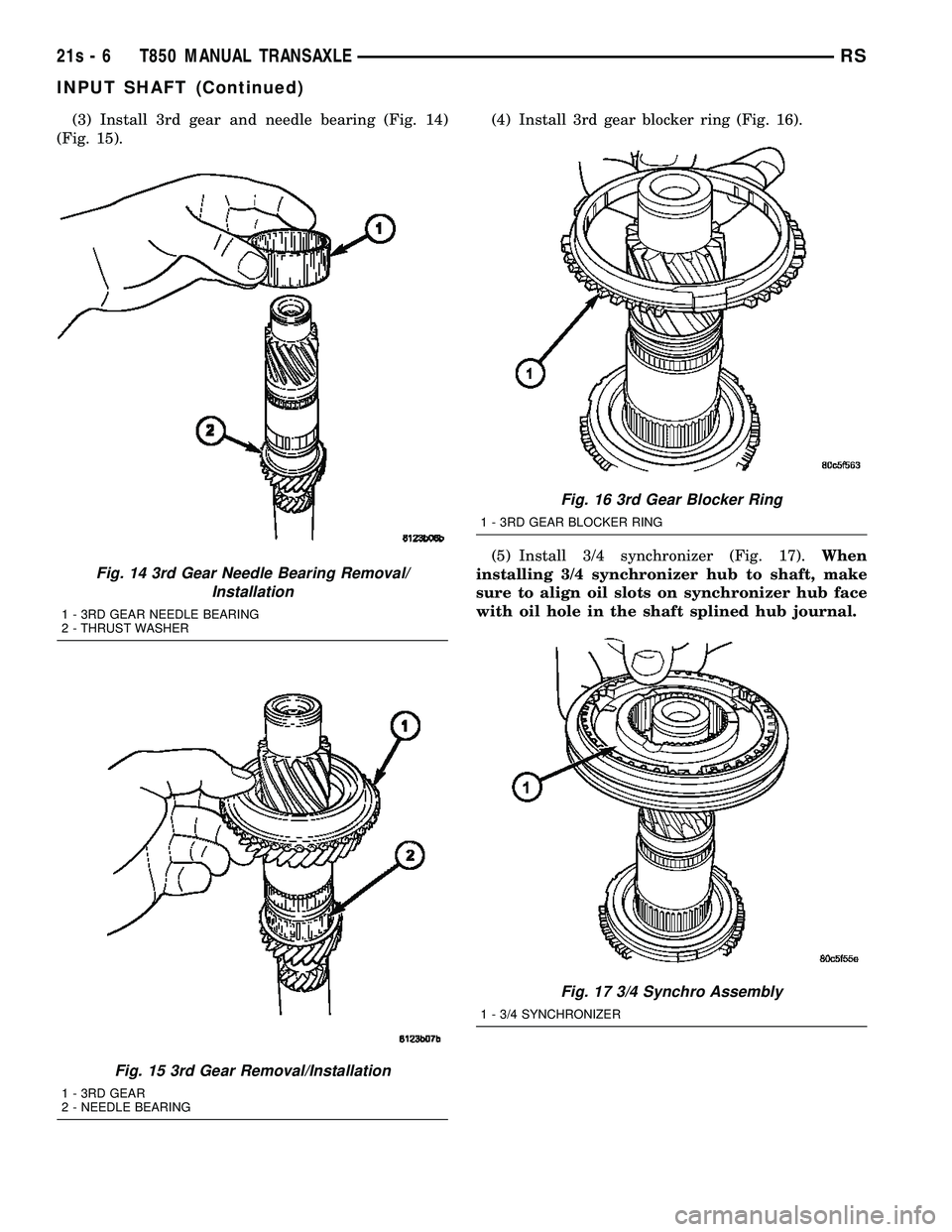
(3) Install 3rd gear and needle bearing (Fig. 14)
(Fig. 15). (4) Install 3rd gear blocker ring (Fig. 16).
(5) Install 3/4 synchronizer (Fig. 17).
When
installing 3/4 synchronizer hub to shaft, make
sure to align oil slots on synchronizer hub face
with oil hole in the shaft splined hub journal.
Fig. 14 3rd Gear Needle Bearing Removal/ Installation
1 - 3RD GEAR NEEDLE BEARING
2 - THRUST WASHER
Fig. 15 3rd Gear Removal/Installation
1 - 3RD GEAR
2 - NEEDLE BEARING
Fig. 16 3rd Gear Blocker Ring
1 - 3RD GEAR BLOCKER RING
Fig. 17 3/4 Synchro Assembly
1 - 3/4 SYNCHRONIZER
21s - 6 T850 MANUAL TRANSAXLERS
INPUT SHAFT (Continued)
Page 1868 of 2585
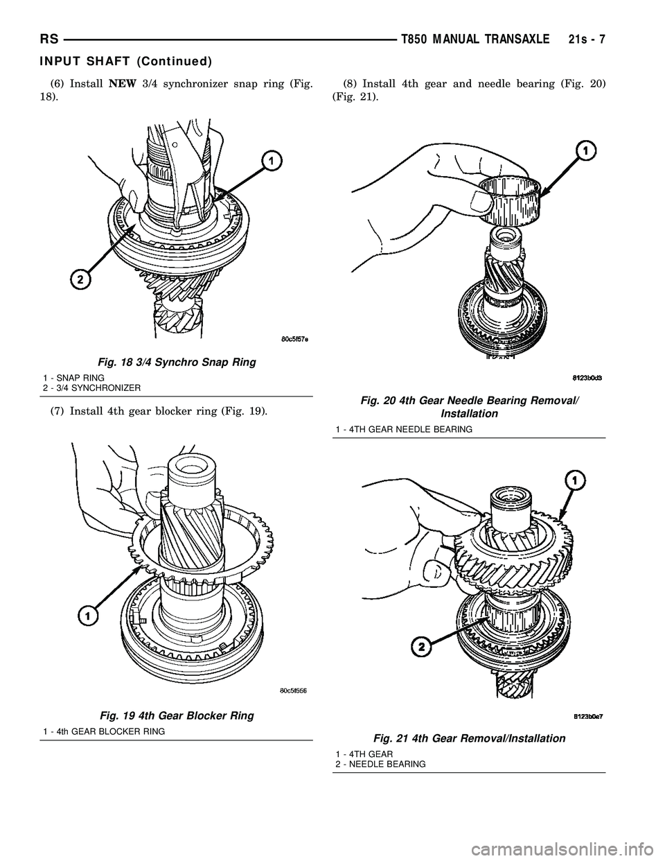
(6) InstallNEW3/4 synchronizer snap ring (Fig.
18).
(7) Install 4th gear blocker ring (Fig. 19). (8) Install 4th gear and needle bearing (Fig. 20)
(Fig. 21).
Fig. 18 3/4 Synchro Snap Ring
1 - SNAP RING
2 - 3/4 SYNCHRONIZER
Fig. 19 4th Gear Blocker Ring
1 - 4th GEAR BLOCKER RING
Fig. 20 4th Gear Needle Bearing Removal/ Installation
1 - 4TH GEAR NEEDLE BEARING
Fig. 21 4th Gear Removal/Installation
1 - 4TH GEAR
2 - NEEDLE BEARING
RS T850 MANUAL TRANSAXLE21s-7
INPUT SHAFT (Continued)
Page 1869 of 2585
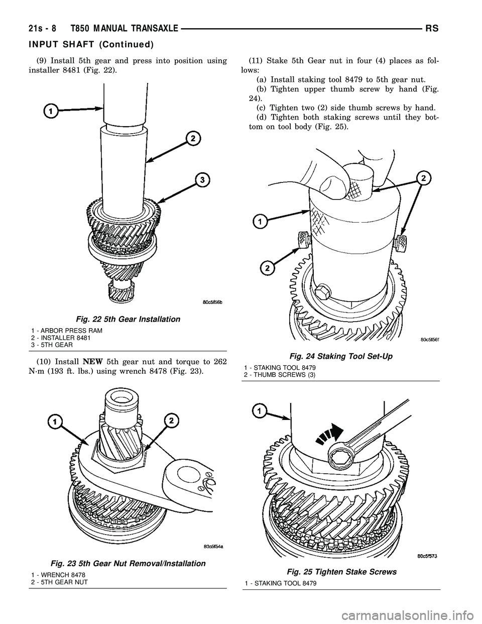
(9) Install 5th gear and press into position using
installer 8481 (Fig. 22).
(10) Install NEW5th gear nut and torque to 262
N´m (193 ft. lbs.) using wrench 8478 (Fig. 23). (11) Stake 5th Gear nut in four (4) places as fol-
lows: (a) Install staking tool 8479 to 5th gear nut.
(b) Tighten upper thumb screw by hand (Fig.
24). (c) Tighten two (2) side thumb screws by hand.
(d) Tighten both staking screws until they bot-
tom on tool body (Fig. 25).
Fig. 24 Staking Tool Set-Up
1 - STAKING TOOL 8479
2 - THUMB SCREWS (3)
Fig. 25 Tighten Stake Screws
1 - STAKING TOOL 8479
Fig. 22 5th Gear Installation
1 - ARBOR PRESS RAM
2 - INSTALLER 8481
3 - 5TH GEAR
Fig. 23 5th Gear Nut Removal/Installation
1 - WRENCH 8478
2 - 5TH GEAR NUT
21s - 8 T850 MANUAL TRANSAXLERS
INPUT SHAFT (Continued)
Page 1870 of 2585
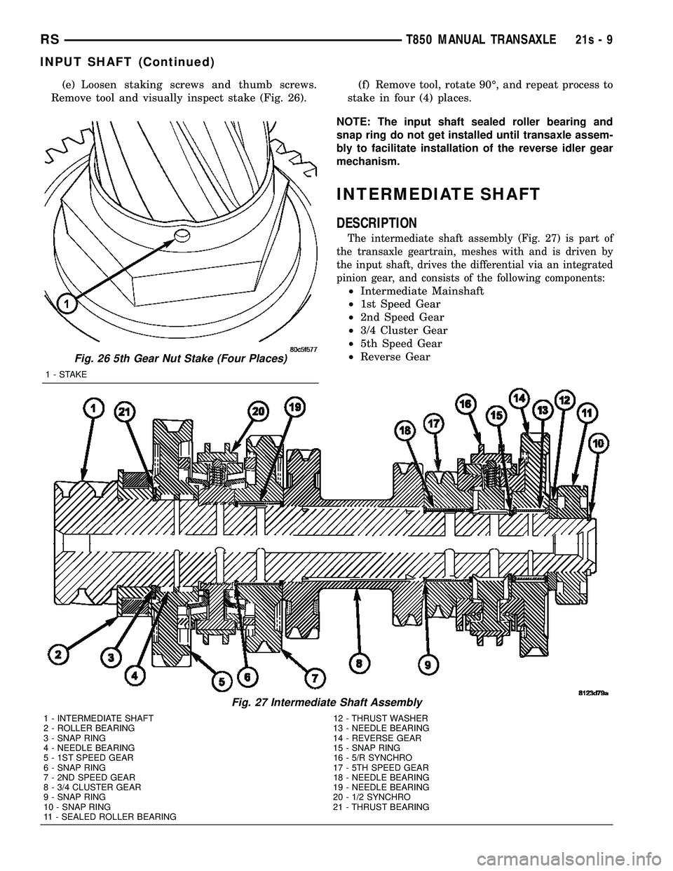
(e) Loosen staking screws and thumb screws.
Remove tool and visually inspect stake (Fig. 26). (f) Remove tool, rotate 90É, and repeat process to
stake in four (4) places.
NOTE: The input shaft sealed roller bearing and
snap ring do not get installed until transaxle assem-
bly to facilitate installation of the reverse idler gear
mechanism.
INTERMEDIATE SHAFT
DESCRIPTION
The intermediate shaft assembly (Fig. 27) is part of
the transaxle geartrain, meshes with and is driven by
the input shaft, drives the differential via an integrated
pinion gear, and consists of the following components:
² Intermediate Mainshaft
² 1st Speed Gear
² 2nd Speed Gear
² 3/4 Cluster Gear
² 5th Speed Gear
² Reverse Gear
Fig. 26 5th Gear Nut Stake (Four Places)
1-STAKE
Fig. 27 Intermediate Shaft Assembly
1 - INTERMEDIATE SHAFT 12 - THRUST WASHER
2 - ROLLER BEARING 13 - NEEDLE BEARING
3 - SNAP RING 14 - REVERSE GEAR
4 - NEEDLE BEARING 15 - SNAP RING
5 - 1ST SPEED GEAR 16 - 5/R SYNCHRO
6 - SNAP RING 17 - 5TH SPEED GEAR
7 - 2ND SPEED GEAR 18 - NEEDLE BEARING
8 - 3/4 CLUSTER GEAR 19 - NEEDLE BEARING
9 - SNAP RING 20 - 1/2 SYNCHRO
10 - SNAP RING 21 - THRUST BEARING
11 - SEALED ROLLER BEARING
RS T850 MANUAL TRANSAXLE21s-9
INPUT SHAFT (Continued)
Trending: headlamp, automatic transmission, oil, height adjustment, drain bolt, roof rack, wiring
