DODGE TOWN AND COUNTRY 2004 Service Manual
TOWN AND COUNTRY 2004
DODGE
DODGE
https://www.carmanualsonline.info/img/12/56919/w960_56919-0.png
DODGE TOWN AND COUNTRY 2004 Service Manual
Trending: oil pressure, spark plugs replace, jacking, oil additives, spark plugs, sensor, tire pressure
Page 1871 of 2585
²1/2 Synchronizer
² 5/R Synchronizer
The intermediate shaft is supported by a caged
roller bearing at the front of the transaxle, and a
sealed roller bearing at the rear of the transaxle.
DISASSEMBLY
CAUTION: Do not re-use snap rings when servicing
the intermediate shaft assembly. Discard upon dis-
assembly and install new ones provided with avail-
able snap ring service kit.
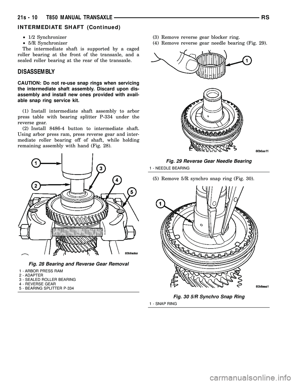
(1) Install intermediate shaft assembly to arbor
press table with bearing splitter P-334 under the
reverse gear. (2) Install 8486-4 button to intermediate shaft.
Using arbor press ram, press reverse gear and inter-
mediate roller bearing off of shaft, while holding
remaining assembly with hand (Fig. 28). (3) Remove reverse gear blocker ring.
(4) Remove reverse gear needle bearing (Fig. 29).
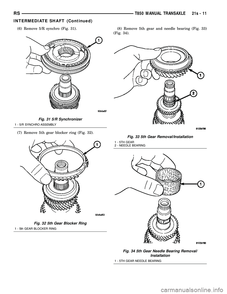
(5) Remove 5/R synchro snap ring (Fig. 30).
Fig. 28 Bearing and Reverse Gear Removal
1 - ARBOR PRESS RAM
2 - ADAPTER
3 - SEALED ROLLER BEARING
4 - REVERSE GEAR
5 - BEARING SPLITTER P-334
Fig. 29 Reverse Gear Needle Bearing
1 - NEEDLE BEARING
Fig. 30 5/R Synchro Snap Ring
1 - SNAP RING
21s - 10 T850 MANUAL TRANSAXLERS
INTERMEDIATE SHAFT (Continued)
Page 1872 of 2585
(6) Remove 5/R synchro (Fig. 31).
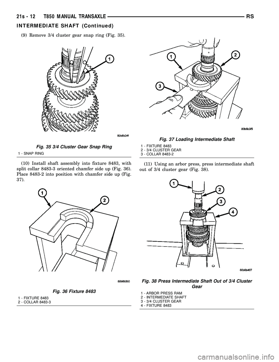
(7) Remove 5th gear blocker ring (Fig. 32).(8) Remove 5th gear and needle bearing (Fig. 33)
(Fig. 34).
Fig. 31 5/R Synchronizer
1 - 5/R SYNCHRO ASSEMBLY
Fig. 32 5th Gear Blocker Ring
1 - 5th GEAR BLOCKER RING
Fig. 33 5th Gear Removal/Installation
1 - 5TH GEAR
2 - NEEDLE BEARING
Fig. 34 5th Gear Needle Bearing Removal/ Installation
1 - 5TH GEAR NEEDLE BEARING
RS T850 MANUAL TRANSAXLE21s-11
INTERMEDIATE SHAFT (Continued)
Page 1873 of 2585
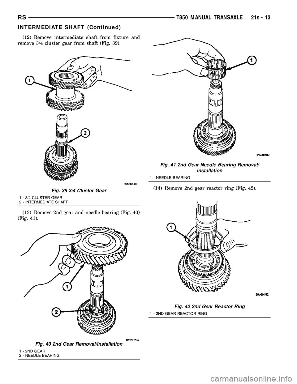
(9) Remove 3/4 cluster gear snap ring (Fig. 35).
(10) Install shaft assembly into fixture 8483, with
split collar 8483-3 oriented chamfer side up (Fig. 36).
Place 8483-2 into position with chamfer side up (Fig.
37). (11) Using an arbor press, press intermediate shaft
out of 3/4 cluster gear (Fig. 38).
Fig. 35 3/4 Cluster Gear Snap Ring
1 - SNAP RING
Fig. 36 Fixture 8483
1 - FIXTURE 8483
2 - COLLAR 8483-3
Fig. 37 Loading Intermediate Shaft
1 - FIXTURE 8483
2 - 3/4 CLUSTER GEAR
3 - COLLAR 8483-2
Fig. 38 Press Intermediate Shaft Out of 3/4 Cluster Gear
1 - ARBOR PRESS RAM
2 - INTERMEDIATE SHAFT
3 - 3/4 CLUSTER GEAR
4 - FIXTURE 8483
21s - 12 T850 MANUAL TRANSAXLERS
INTERMEDIATE SHAFT (Continued)
Page 1874 of 2585
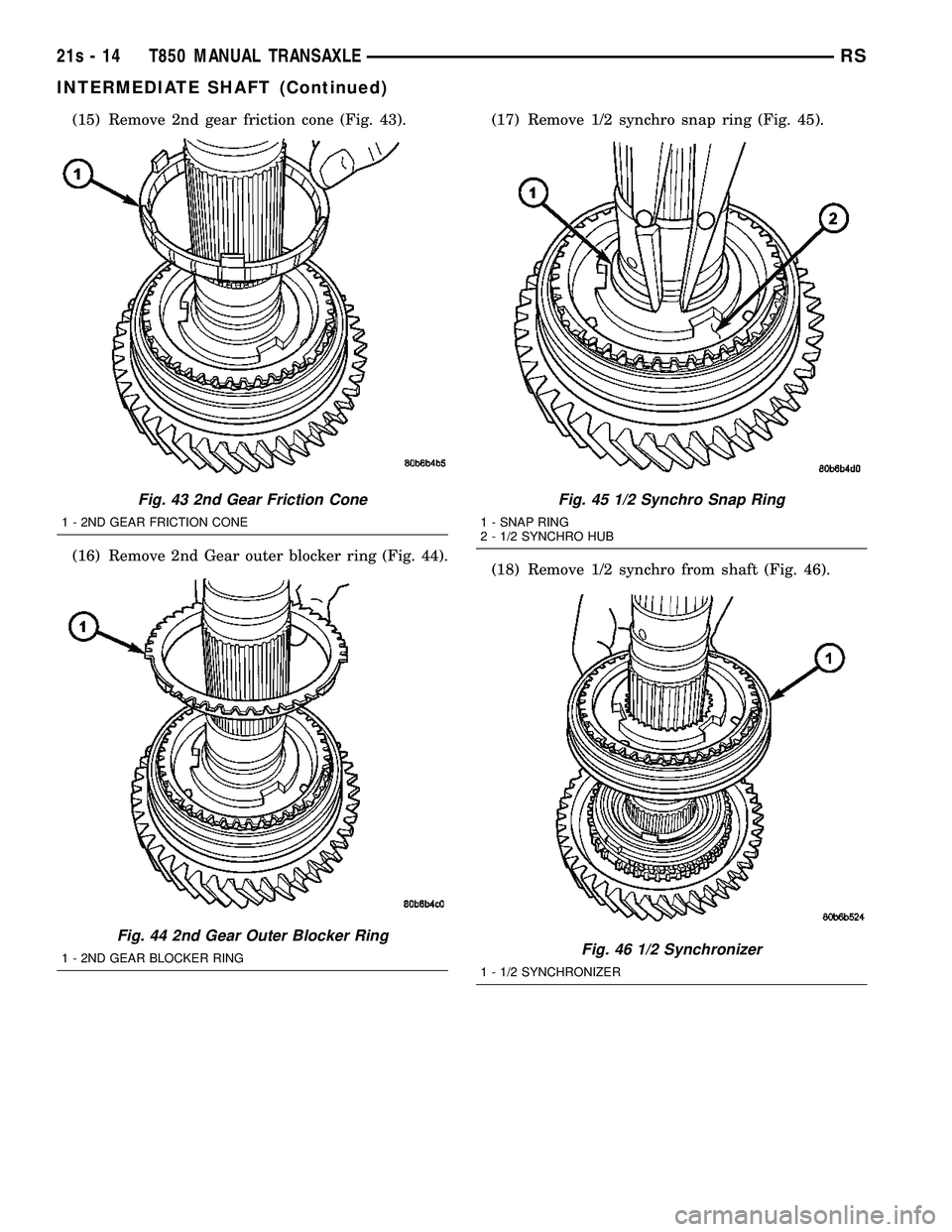
(12) Remove intermediate shaft from fixture and
remove 3/4 cluster gear from shaft (Fig. 39).
(13) Remove 2nd gear and needle bearing (Fig. 40)
(Fig. 41). (14) Remove 2nd gear reactor ring (Fig. 42).
Fig. 39 3/4 Cluster Gear
1 - 3/4 CLUSTER GEAR
2 - INTERMEDIATE SHAFT
Fig. 40 2nd Gear Removal/Installation
1 - 2ND GEAR
2 - NEEDLE BEARING
Fig. 41 2nd Gear Needle Bearing Removal/
Installation
1 - NEEDLE BEARING
Fig. 42 2nd Gear Reactor Ring
1 - 2ND GEAR REACTOR RING
RS T850 MANUAL TRANSAXLE21s-13
INTERMEDIATE SHAFT (Continued)
Page 1875 of 2585
(15) Remove 2nd gear friction cone (Fig. 43).
(16) Remove 2nd Gear outer blocker ring (Fig. 44).(17) Remove 1/2 synchro snap ring (Fig. 45).
(18) Remove 1/2 synchro from shaft (Fig. 46).
Fig. 43 2nd Gear Friction Cone
1 - 2ND GEAR FRICTION CONE
Fig. 44 2nd Gear Outer Blocker Ring
1 - 2ND GEAR BLOCKER RING
Fig. 45 1/2 Synchro Snap Ring
1 - SNAP RING
2 - 1/2 SYNCHRO HUB
Fig. 46 1/2 Synchronizer
1 - 1/2 SYNCHRONIZER
21s - 14 T850 MANUAL TRANSAXLERS
INTERMEDIATE SHAFT (Continued)
Page 1876 of 2585
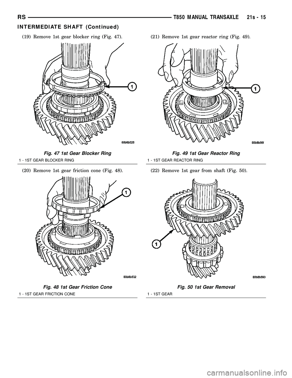
(19) Remove 1st gear blocker ring (Fig. 47).
(20) Remove 1st gear friction cone (Fig. 48).(21) Remove 1st gear reactor ring (Fig. 49).
(22) Remove 1st gear from shaft (Fig. 50).
Fig. 47 1st Gear Blocker Ring
1 - 1ST GEAR BLOCKER RING
Fig. 48 1st Gear Friction Cone
1 - 1ST GEAR FRICTION CONE
Fig. 49 1st Gear Reactor Ring
1 - 1ST GEAR REACTOR RING
Fig. 50 1st Gear Removal
1 - 1ST GEAR
RS
T850 MANUAL TRANSAXLE21s-15
INTERMEDIATE SHAFT (Continued)
Page 1877 of 2585
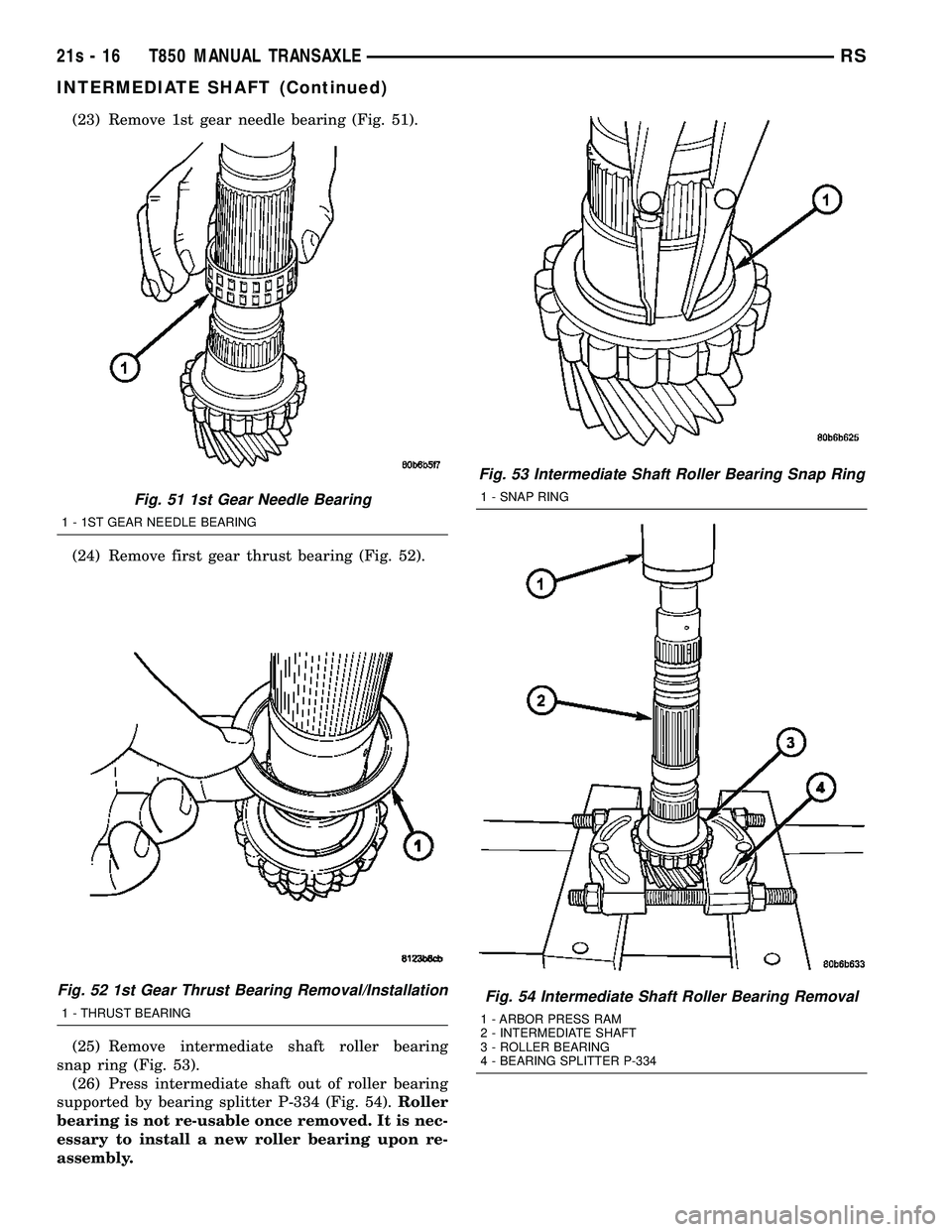
(23) Remove 1st gear needle bearing (Fig. 51).
(24) Remove first gear thrust bearing (Fig. 52).
(25) Remove intermediate shaft roller bearing
snap ring (Fig. 53). (26) Press intermediate shaft out of roller bearing
supported by bearing splitter P-334 (Fig. 54). Roller
bearing is not re-usable once removed. It is nec-
essary to install a new roller bearing upon re-
assembly.
Fig. 51 1st Gear Needle Bearing
1 - 1ST GEAR NEEDLE BEARING
Fig. 52 1st Gear Thrust Bearing Removal/Installation
1 - THRUST BEARING
Fig. 53 Intermediate Shaft Roller Bearing Snap Ring
1 - SNAP RING
Fig. 54 Intermediate Shaft Roller Bearing Removal
1 - ARBOR PRESS RAM
2 - INTERMEDIATE SHAFT
3 - ROLLER BEARING
4 - BEARING SPLITTER P-334
21s - 16 T850 MANUAL TRANSAXLERS
INTERMEDIATE SHAFT (Continued)
Page 1878 of 2585
ASSEMBLY
NOTE: Do not re-use snap rings when servicing the
intermediate shaft assembly. Discard snap rings
and install new ones provided with available snap
ring service kit.
NOTE: When installing 1/2 & 5/R synchronizers,
make sure to align oil slots on synchronizer hub
face with oil hold in the shaft splined hub journal.
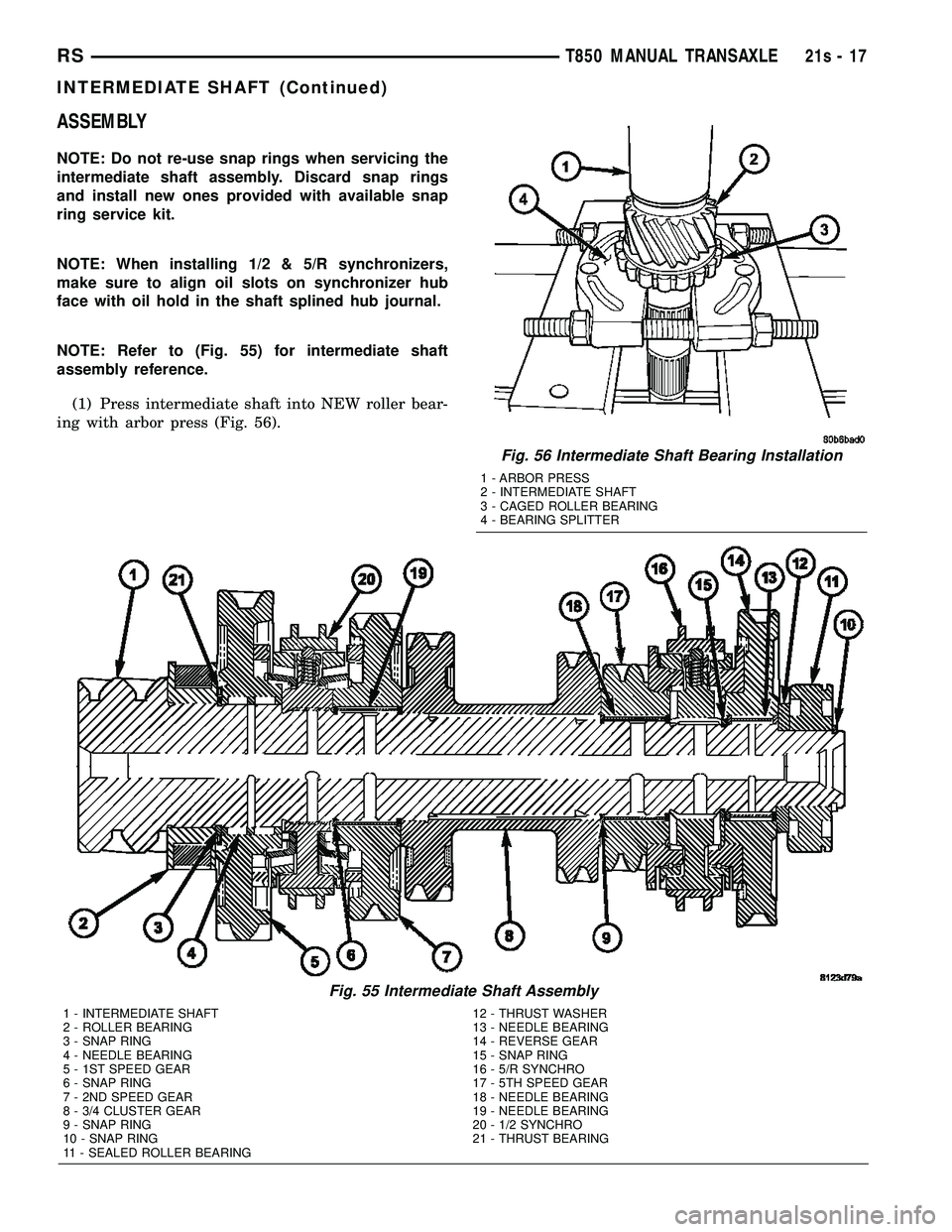
NOTE: Refer to (Fig. 55) for intermediate shaft
assembly reference.(1) Press intermediate shaft into NEW roller bear-
ing with arbor press (Fig. 56).
Fig. 55 Intermediate Shaft Assembly
1 - INTERMEDIATE SHAFT 12 - THRUST WASHER
2 - ROLLER BEARING 13 - NEEDLE BEARING
3 - SNAP RING 14 - REVERSE GEAR
4 - NEEDLE BEARING 15 - SNAP RING
5 - 1ST SPEED GEAR 16 - 5/R SYNCHRO
6 - SNAP RING 17 - 5TH SPEED GEAR
7 - 2ND SPEED GEAR 18 - NEEDLE BEARING
8 - 3/4 CLUSTER GEAR 19 - NEEDLE BEARING
9 - SNAP RING 20 - 1/2 SYNCHRO
10 - SNAP RING 21 - THRUST BEARING
11 - SEALED ROLLER BEARING
Fig. 56 Intermediate Shaft Bearing Installation
1 - ARBOR PRESS
2 - INTERMEDIATE SHAFT
3 - CAGED ROLLER BEARING
4 - BEARING SPLITTER
RS T850 MANUAL TRANSAXLE21s-17
INTERMEDIATE SHAFT (Continued)
Page 1879 of 2585
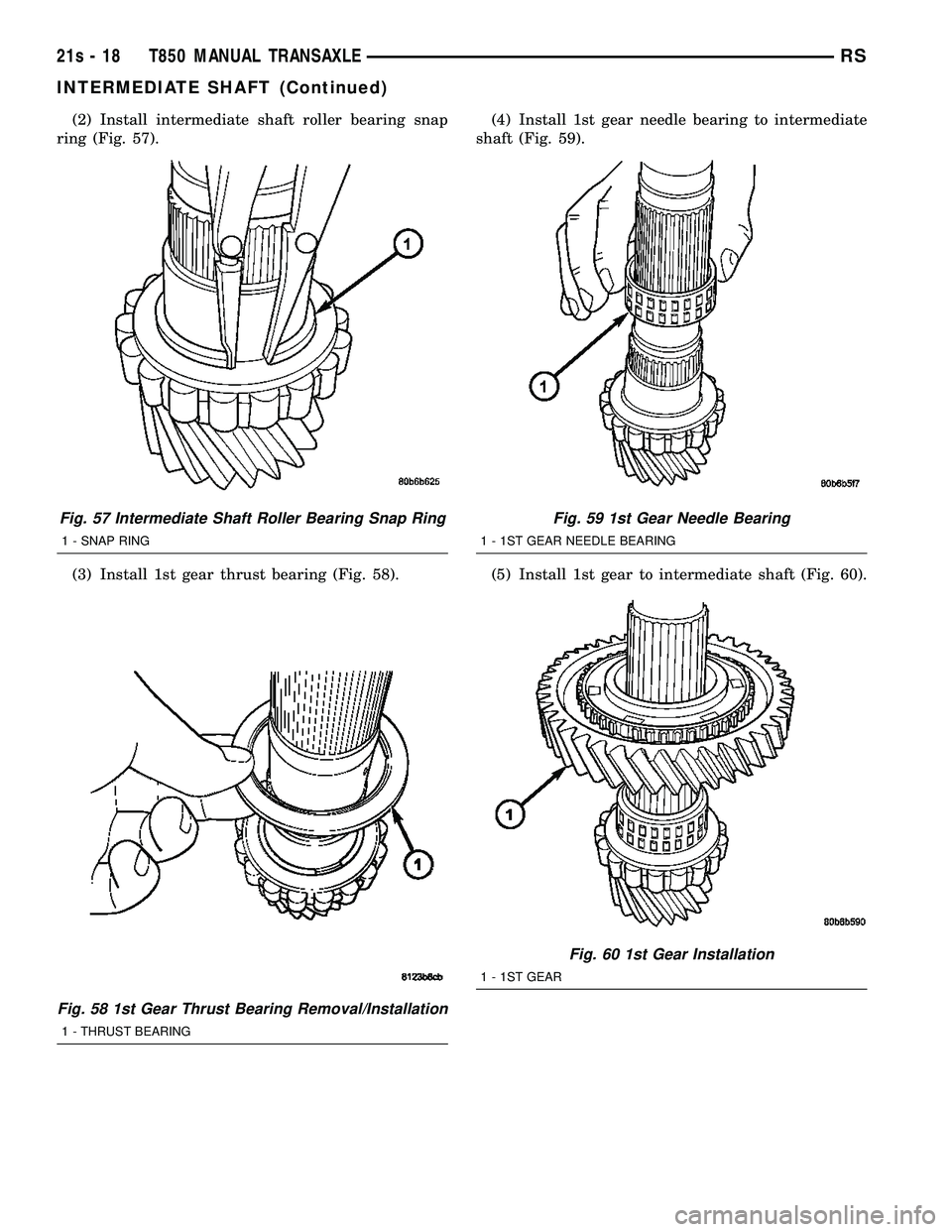
(2) Install intermediate shaft roller bearing snap
ring (Fig. 57).
(3) Install 1st gear thrust bearing (Fig. 58). (4) Install 1st gear needle bearing to intermediate
shaft (Fig. 59).
(5) Install 1st gear to intermediate shaft (Fig. 60).
Fig. 57 Intermediate Shaft Roller Bearing Snap Ring
1 - SNAP RING
Fig. 58 1st Gear Thrust Bearing Removal/Installation
1 - THRUST BEARING
Fig. 59 1st Gear Needle Bearing
1 - 1ST GEAR NEEDLE BEARING
Fig. 60 1st Gear Installation
1 - 1ST GEAR
21s - 18 T850 MANUAL TRANSAXLERS
INTERMEDIATE SHAFT (Continued)
Page 1880 of 2585
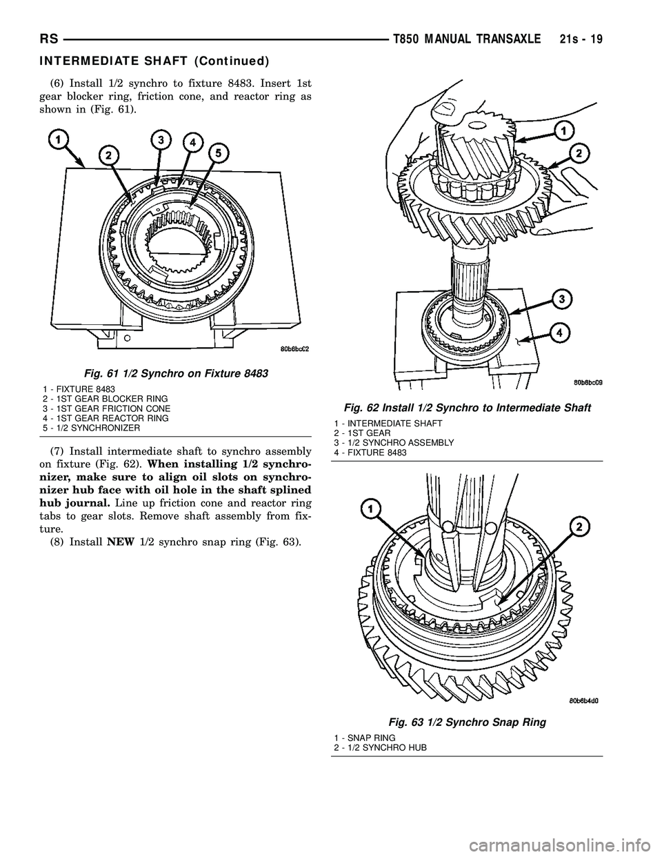
(6) Install 1/2 synchro to fixture 8483. Insert 1st
gear blocker ring, friction cone, and reactor ring as
shown in (Fig. 61).
(7) Install intermediate shaft to synchro assembly
on fixture (Fig. 62). When installing 1/2 synchro-
nizer, make sure to align oil slots on synchro-
nizer hub face with oil hole in the shaft splined
hub journal. Line up friction cone and reactor ring
tabs to gear slots. Remove shaft assembly from fix-
ture. (8) Install NEW1/2 synchro snap ring (Fig. 63).
Fig. 61 1/2 Synchro on Fixture 8483
1 - FIXTURE 8483
2 - 1ST GEAR BLOCKER RING
3 - 1ST GEAR FRICTION CONE
4 - 1ST GEAR REACTOR RING
5 - 1/2 SYNCHRONIZER
Fig. 62 Install 1/2 Synchro to Intermediate Shaft
1 - INTERMEDIATE SHAFT
2 - 1ST GEAR
3 - 1/2 SYNCHRO ASSEMBLY
4 - FIXTURE 8483
Fig. 63 1/2 Synchro Snap Ring
1 - SNAP RING
2 - 1/2 SYNCHRO HUB
RS T850 MANUAL TRANSAXLE21s-19
INTERMEDIATE SHAFT (Continued)
Trending: tire pressure reset, dimensions, jump start terminals, CD player, ESP, open gas tank, gas type

