DODGE TOWN AND COUNTRY 2004 Service Manual
Manufacturer: DODGE, Model Year: 2004, Model line: TOWN AND COUNTRY, Model: DODGE TOWN AND COUNTRY 2004Pages: 2585, PDF Size: 62.54 MB
Page 691 of 2585
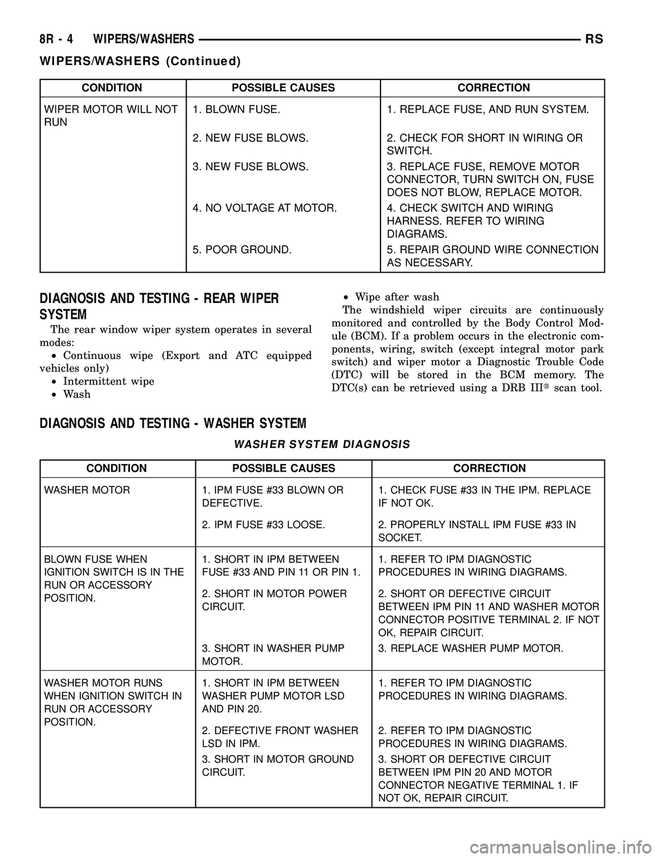
CONDITION POSSIBLE CAUSES CORRECTION
WIPER MOTOR WILL NOT
RUN1. BLOWN FUSE. 1. REPLACE FUSE, AND RUN SYSTEM.
2. NEW FUSE BLOWS. 2. CHECK FOR SHORT IN WIRING OR
SWITCH.
3. NEW FUSE BLOWS. 3. REPLACE FUSE, REMOVE MOTOR
CONNECTOR, TURN SWITCH ON, FUSE
DOES NOT BLOW, REPLACE MOTOR.
4. NO VOLTAGE AT MOTOR. 4. CHECK SWITCH AND WIRING
HARNESS. REFER TO WIRING
DIAGRAMS.
5. POOR GROUND. 5. REPAIR GROUND WIRE CONNECTION
AS NECESSARY.
DIAGNOSIS AND TESTING - REAR WIPER
SYSTEM
The rear window wiper system operates in several
modes:
²Continuous wipe (Export and ATC equipped
vehicles only)
²Intermittent wipe
²Wash²Wipe after wash
The windshield wiper circuits are continuously
monitored and controlled by the Body Control Mod-
ule (BCM). If a problem occurs in the electronic com-
ponents, wiring, switch (except integral motor park
switch) and wiper motor a Diagnostic Trouble Code
(DTC) will be stored in the BCM memory. The
DTC(s) can be retrieved using a DRB IIItscan tool.
DIAGNOSIS AND TESTING - WASHER SYSTEM
WASHER SYSTEM DIAGNOSIS
CONDITION POSSIBLE CAUSES CORRECTION
WASHER MOTOR 1. IPM FUSE #33 BLOWN OR
DEFECTIVE.1. CHECK FUSE #33 IN THE IPM. REPLACE
IF NOT OK.
2. IPM FUSE #33 LOOSE. 2. PROPERLY INSTALL IPM FUSE #33 IN
SOCKET.
BLOWN FUSE WHEN
IGNITION SWITCH IS IN THE
RUN OR ACCESSORY
POSITION.1. SHORT IN IPM BETWEEN
FUSE #33 AND PIN 11 OR PIN 1.1. REFER TO IPM DIAGNOSTIC
PROCEDURES IN WIRING DIAGRAMS.
2. SHORT IN MOTOR POWER
CIRCUIT.2. SHORT OR DEFECTIVE CIRCUIT
BETWEEN IPM PIN 11 AND WASHER MOTOR
CONNECTOR POSITIVE TERMINAL 2. IF NOT
OK, REPAIR CIRCUIT.
3. SHORT IN WASHER PUMP
MOTOR.3. REPLACE WASHER PUMP MOTOR.
WASHER MOTOR RUNS
WHEN IGNITION SWITCH IN
RUN OR ACCESSORY
POSITION.1. SHORT IN IPM BETWEEN
WASHER PUMP MOTOR LSD
AND PIN 20.1. REFER TO IPM DIAGNOSTIC
PROCEDURES IN WIRING DIAGRAMS.
2. DEFECTIVE FRONT WASHER
LSD IN IPM.2. REFER TO IPM DIAGNOSTIC
PROCEDURES IN WIRING DIAGRAMS.
3. SHORT IN MOTOR GROUND
CIRCUIT.3. SHORT OR DEFECTIVE CIRCUIT
BETWEEN IPM PIN 20 AND MOTOR
CONNECTOR NEGATIVE TERMINAL 1. IF
NOT OK, REPAIR CIRCUIT.
8R - 4 WIPERS/WASHERSRS
WIPERS/WASHERS (Continued)
Page 692 of 2585
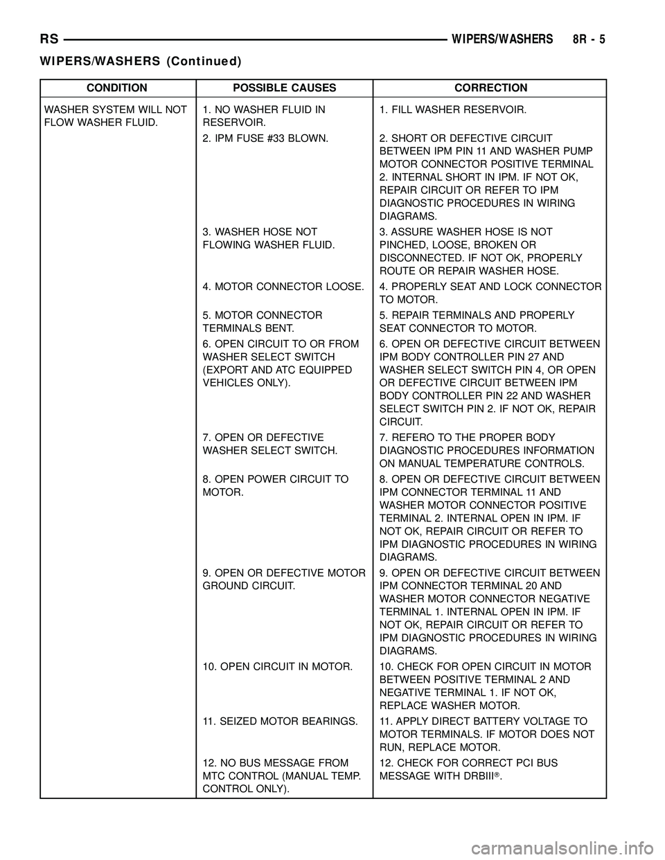
CONDITION POSSIBLE CAUSES CORRECTION
WASHER SYSTEM WILL NOT
FLOW WASHER FLUID.1. NO WASHER FLUID IN
RESERVOIR.1. FILL WASHER RESERVOIR.
2. IPM FUSE #33 BLOWN. 2. SHORT OR DEFECTIVE CIRCUIT
BETWEEN IPM PIN 11 AND WASHER PUMP
MOTOR CONNECTOR POSITIVE TERMINAL
2. INTERNAL SHORT IN IPM. IF NOT OK,
REPAIR CIRCUIT OR REFER TO IPM
DIAGNOSTIC PROCEDURES IN WIRING
DIAGRAMS.
3. WASHER HOSE NOT
FLOWING WASHER FLUID.3. ASSURE WASHER HOSE IS NOT
PINCHED, LOOSE, BROKEN OR
DISCONNECTED. IF NOT OK, PROPERLY
ROUTE OR REPAIR WASHER HOSE.
4. MOTOR CONNECTOR LOOSE. 4. PROPERLY SEAT AND LOCK CONNECTOR
TO MOTOR.
5. MOTOR CONNECTOR
TERMINALS BENT.5. REPAIR TERMINALS AND PROPERLY
SEAT CONNECTOR TO MOTOR.
6. OPEN CIRCUIT TO OR FROM
WASHER SELECT SWITCH
(EXPORT AND ATC EQUIPPED
VEHICLES ONLY).6. OPEN OR DEFECTIVE CIRCUIT BETWEEN
IPM BODY CONTROLLER PIN 27 AND
WASHER SELECT SWITCH PIN 4, OR OPEN
OR DEFECTIVE CIRCUIT BETWEEN IPM
BODY CONTROLLER PIN 22 AND WASHER
SELECT SWITCH PIN 2. IF NOT OK, REPAIR
CIRCUIT.
7. OPEN OR DEFECTIVE
WASHER SELECT SWITCH.7. REFERO TO THE PROPER BODY
DIAGNOSTIC PROCEDURES INFORMATION
ON MANUAL TEMPERATURE CONTROLS.
8. OPEN POWER CIRCUIT TO
MOTOR.8. OPEN OR DEFECTIVE CIRCUIT BETWEEN
IPM CONNECTOR TERMINAL 11 AND
WASHER MOTOR CONNECTOR POSITIVE
TERMINAL 2. INTERNAL OPEN IN IPM. IF
NOT OK, REPAIR CIRCUIT OR REFER TO
IPM DIAGNOSTIC PROCEDURES IN WIRING
DIAGRAMS.
9. OPEN OR DEFECTIVE MOTOR
GROUND CIRCUIT.9. OPEN OR DEFECTIVE CIRCUIT BETWEEN
IPM CONNECTOR TERMINAL 20 AND
WASHER MOTOR CONNECTOR NEGATIVE
TERMINAL 1. INTERNAL OPEN IN IPM. IF
NOT OK, REPAIR CIRCUIT OR REFER TO
IPM DIAGNOSTIC PROCEDURES IN WIRING
DIAGRAMS.
10. OPEN CIRCUIT IN MOTOR. 10. CHECK FOR OPEN CIRCUIT IN MOTOR
BETWEEN POSITIVE TERMINAL 2 AND
NEGATIVE TERMINAL 1. IF NOT OK,
REPLACE WASHER MOTOR.
11. SEIZED MOTOR BEARINGS. 11. APPLY DIRECT BATTERY VOLTAGE TO
MOTOR TERMINALS. IF MOTOR DOES NOT
RUN, REPLACE MOTOR.
12. NO BUS MESSAGE FROM
MTC CONTROL (MANUAL TEMP.
CONTROL ONLY).12. CHECK FOR CORRECT PCI BUS
MESSAGE WITH DRBIIIT.
RSWIPERS/WASHERS8R-5
WIPERS/WASHERS (Continued)
Page 693 of 2585
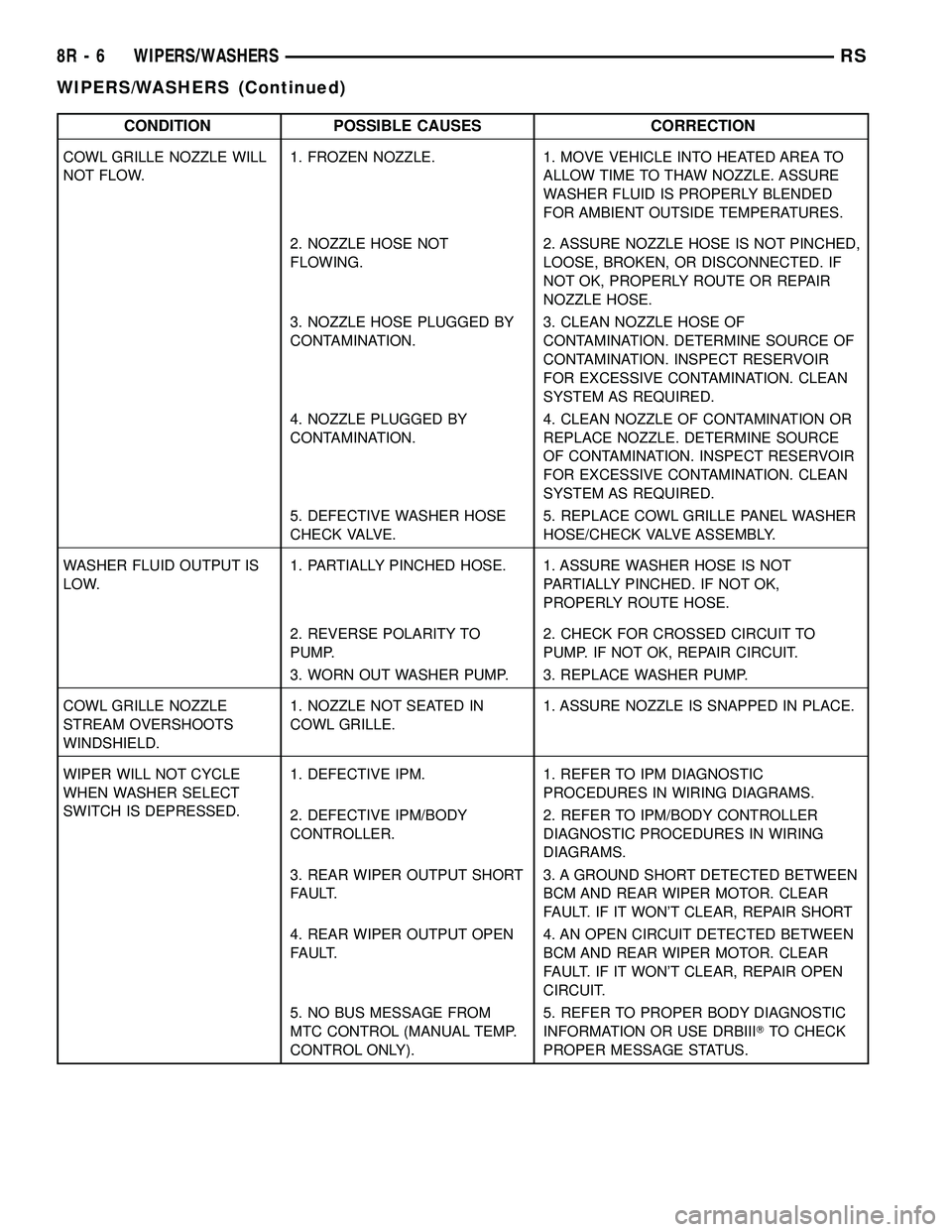
CONDITION POSSIBLE CAUSES CORRECTION
COWL GRILLE NOZZLE WILL
NOT FLOW.1. FROZEN NOZZLE. 1. MOVE VEHICLE INTO HEATED AREA TO
ALLOW TIME TO THAW NOZZLE. ASSURE
WASHER FLUID IS PROPERLY BLENDED
FOR AMBIENT OUTSIDE TEMPERATURES.
2. NOZZLE HOSE NOT
FLOWING.2. ASSURE NOZZLE HOSE IS NOT PINCHED,
LOOSE, BROKEN, OR DISCONNECTED. IF
NOT OK, PROPERLY ROUTE OR REPAIR
NOZZLE HOSE.
3. NOZZLE HOSE PLUGGED BY
CONTAMINATION.3. CLEAN NOZZLE HOSE OF
CONTAMINATION. DETERMINE SOURCE OF
CONTAMINATION. INSPECT RESERVOIR
FOR EXCESSIVE CONTAMINATION. CLEAN
SYSTEM AS REQUIRED.
4. NOZZLE PLUGGED BY
CONTAMINATION.4. CLEAN NOZZLE OF CONTAMINATION OR
REPLACE NOZZLE. DETERMINE SOURCE
OF CONTAMINATION. INSPECT RESERVOIR
FOR EXCESSIVE CONTAMINATION. CLEAN
SYSTEM AS REQUIRED.
5. DEFECTIVE WASHER HOSE
CHECK VALVE.5. REPLACE COWL GRILLE PANEL WASHER
HOSE/CHECK VALVE ASSEMBLY.
WASHER FLUID OUTPUT IS
LOW.1. PARTIALLY PINCHED HOSE. 1. ASSURE WASHER HOSE IS NOT
PARTIALLY PINCHED. IF NOT OK,
PROPERLY ROUTE HOSE.
2. REVERSE POLARITY TO
PUMP.2. CHECK FOR CROSSED CIRCUIT TO
PUMP. IF NOT OK, REPAIR CIRCUIT.
3. WORN OUT WASHER PUMP. 3. REPLACE WASHER PUMP.
COWL GRILLE NOZZLE
STREAM OVERSHOOTS
WINDSHIELD.1. NOZZLE NOT SEATED IN
COWL GRILLE.1. ASSURE NOZZLE IS SNAPPED IN PLACE.
WIPER WILL NOT CYCLE
WHEN WASHER SELECT
SWITCH IS DEPRESSED.1. DEFECTIVE IPM. 1. REFER TO IPM DIAGNOSTIC
PROCEDURES IN WIRING DIAGRAMS.
2. DEFECTIVE IPM/BODY
CONTROLLER.2. REFER TO IPM/BODY CONTROLLER
DIAGNOSTIC PROCEDURES IN WIRING
DIAGRAMS.
3. REAR WIPER OUTPUT SHORT
FAULT.3. A GROUND SHORT DETECTED BETWEEN
BCM AND REAR WIPER MOTOR. CLEAR
FAULT. IF IT WON'T CLEAR, REPAIR SHORT
4. REAR WIPER OUTPUT OPEN
FAULT.4. AN OPEN CIRCUIT DETECTED BETWEEN
BCM AND REAR WIPER MOTOR. CLEAR
FAULT. IF IT WON'T CLEAR, REPAIR OPEN
CIRCUIT.
5. NO BUS MESSAGE FROM
MTC CONTROL (MANUAL TEMP.
CONTROL ONLY).5. REFER TO PROPER BODY DIAGNOSTIC
INFORMATION OR USE DRBIIITTO CHECK
PROPER MESSAGE STATUS.
8R - 6 WIPERS/WASHERSRS
WIPERS/WASHERS (Continued)
Page 694 of 2585
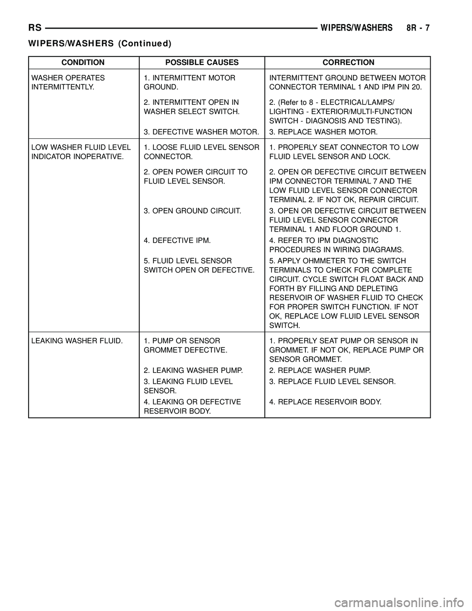
CONDITION POSSIBLE CAUSES CORRECTION
WASHER OPERATES
INTERMITTENTLY.1. INTERMITTENT MOTOR
GROUND.INTERMITTENT GROUND BETWEEN MOTOR
CONNECTOR TERMINAL 1 AND IPM PIN 20.
2. INTERMITTENT OPEN IN
WASHER SELECT SWITCH.2. (Refer to 8 - ELECTRICAL/LAMPS/
LIGHTING - EXTERIOR/MULTI-FUNCTION
SWITCH - DIAGNOSIS AND TESTING).
3. DEFECTIVE WASHER MOTOR. 3. REPLACE WASHER MOTOR.
LOW WASHER FLUID LEVEL
INDICATOR INOPERATIVE.1. LOOSE FLUID LEVEL SENSOR
CONNECTOR.1. PROPERLY SEAT CONNECTOR TO LOW
FLUID LEVEL SENSOR AND LOCK.
2. OPEN POWER CIRCUIT TO
FLUID LEVEL SENSOR.2. OPEN OR DEFECTIVE CIRCUIT BETWEEN
IPM CONNECTOR TERMINAL 7 AND THE
LOW FLUID LEVEL SENSOR CONNECTOR
TERMINAL 2. IF NOT OK, REPAIR CIRCUIT.
3. OPEN GROUND CIRCUIT. 3. OPEN OR DEFECTIVE CIRCUIT BETWEEN
FLUID LEVEL SENSOR CONNECTOR
TERMINAL 1 AND FLOOR GROUND 1.
4. DEFECTIVE IPM. 4. REFER TO IPM DIAGNOSTIC
PROCEDURES IN WIRING DIAGRAMS.
5. FLUID LEVEL SENSOR
SWITCH OPEN OR DEFECTIVE.5. APPLY OHMMETER TO THE SWITCH
TERMINALS TO CHECK FOR COMPLETE
CIRCUIT. CYCLE SWITCH FLOAT BACK AND
FORTH BY FILLING AND DEPLETING
RESERVOIR OF WASHER FLUID TO CHECK
FOR PROPER SWITCH FUNCTION. IF NOT
OK, REPLACE LOW FLUID LEVEL SENSOR
SWITCH.
LEAKING WASHER FLUID. 1. PUMP OR SENSOR
GROMMET DEFECTIVE.1. PROPERLY SEAT PUMP OR SENSOR IN
GROMMET. IF NOT OK, REPLACE PUMP OR
SENSOR GROMMET.
2. LEAKING WASHER PUMP. 2. REPLACE WASHER PUMP.
3. LEAKING FLUID LEVEL
SENSOR.3. REPLACE FLUID LEVEL SENSOR.
4. LEAKING OR DEFECTIVE
RESERVOIR BODY.4. REPLACE RESERVOIR BODY.
RSWIPERS/WASHERS8R-7
WIPERS/WASHERS (Continued)
Page 695 of 2585
FRONT WASHER PUMP
MOTOR
REMOVAL
(1) Disconnect and isolate the battery negative
cable.
(2) Remove the engine fresh air housing inside the
engine compartment (Refer to 9 - ENGINE/AIR
INTAKE SYSTEM/AIR CLEANER HOUSING -
REMOVAL).
(3) Disconnect the washer hose at the in-line con-
nector forward of the cowl grille so that the in-line
connector remains with the washer hose from the
fresh air plenum.
(4) Disconnect the washer hose from the hose clip
located on the front fender side shield.
(5) Remove the filler tube screw.
(6) Hoist and support vehicle on hoist or jack
stands.
(7) Remove the right front wheel and tire assembly
(Refer to 22 - TIRES/WHEELS - REMOVAL).
(8) Disconnect the left right front wheelhouse
splash shield and move aside (Refer to 23 - BODY/
EXTERIOR/WHEELHOUSE SPLASH SHIELD -
REMOVAL).
(9) Drain washer fluid from the reservoir and into
a suitable clean container. This can be done by dis-
connecting the windshield washer hose from the
front (outboard) washer pump and allowing the
washer fluid to drain into a container through a tem-
porary jumper hose connected to the front washer
pump.
(10) Disconnect the electrical body harness connec-
tors to the washer pump motors and the fluid level
sensor. Slide the red lock on the connector to the
release position, then, depress the black tab and pull
the connector off the pump or sensor.
(11) Remove the two reservoir mounting screws.
(12) Disconnect the reservoir from the body mount
by raising the reservoir upward slightly and then
down so that the reservoir filler neck and front
washer hose pull through the opening in the front
fender side shield.
(13) Remove pump from reservoir by pulling pump
upper retention tab away from reservoir cavity and
then lifting pump up from mounting grommet. Do
not damage reservoir/pump sealing surface or punc-
ture reservoir during removal.
(14) Remove pump grommet and discard.
INSTALLATION
(1) Use new grommet when installing a new pump
assembly.
(2) Assure pump upper retention tab is pressed
into reservoir slot and that pump is rotated flatagainst the reservoir and that pump connector is fac-
ing up in the fully seated position. Assure the pump
is aligned to and fully seated in the reservoir cavity.
(3) Push filler neck and front washer hose through
the opening in the front fender side shield. Connect
the reservoir to the body mount by lowering the res-
ervoir down.
(4) Install the two reservoir mounting screws.
Torque screws to 8.5 - 11.3 N´m (75 - 100 in. lbs.).
(5) Connect the electrical body harness connectors
to the washer pump motors and the fluid level sen-
sor. Slide the red lock on the connector to the closed
or locked position.
(6) Assure that washer hose is properly routed to
prevent pinching and possible inoperative washers.
(7) Connect the left right front wheelhouse splash
shield and move aside (Refer to 23 - BODY/EXTERI-
OR/WHEELHOUSE SPLASH SHIELD - INSTALLA-
TION).
(8) Install the right front wheel and tire assembly
(Refer to 22 - TIRES/WHEELS - INSTALLATION).
(9) lower vehicle from hoist or jack stands.
(10) Install the filler tube screw. Torque screw to
8.5 - 11.3 N´m (75 - 100 in. lbs.).
(11) Connect the washer hose to the hose clip
located on the front fender side shield.
(12) Connect the washer hose at the in-line con-
nector forward of the cowl grille.
(13) Install the engine fresh air housing inside the
engine compartment (Refer to 9 - ENGINE/AIR
INTAKE SYSTEM/AIR CLEANER HOUSING -
INSTALLATION).
(14) Connect the battery negative cable.
(15) Verify system operation.
FRONT WIPER ARMS
STANDARD PROCEDURE - FRONT WIPER ARM
ALIGNMENT
(1) Verify wiper blade element condition and wiper
arm spring tension. Run wipers in low speed mode
while applying water to the windshield. Observe the
wiper blade that is chattering or skipping across the
windshield. If the wiper element is not rolling over
when the wiper direction reverses, align the wiper
arm. The extension bar portion of the wiper arm
must be twisted in the proper direction to allow the
wiper element to roll over when the direction
reverses.
(2) Place two small adjustable wrenches placed 50
mm (2 in.) apart on the wiper arm extension rod.
(3) Twist the extension rod slightly in the opposite
direction that the element is laying on the wind-
shield while holding the wrench closest to the pivot
stationary.
8R - 8 WIPERS/WASHERSRS
Page 696 of 2585
(4) Repeat Step 1, and align as necessary until
wiper stops chattering and wipes the windshield
clear.
REMOVAL
CAUTION: The driver side wiper arm must be
parked above the passenger side. Failure to do so
will result in damage to the arms, blades or system.
(1) Lift the arm cap upward.
(2) Remove the nut holding wiper arm to the wiper
pivot.
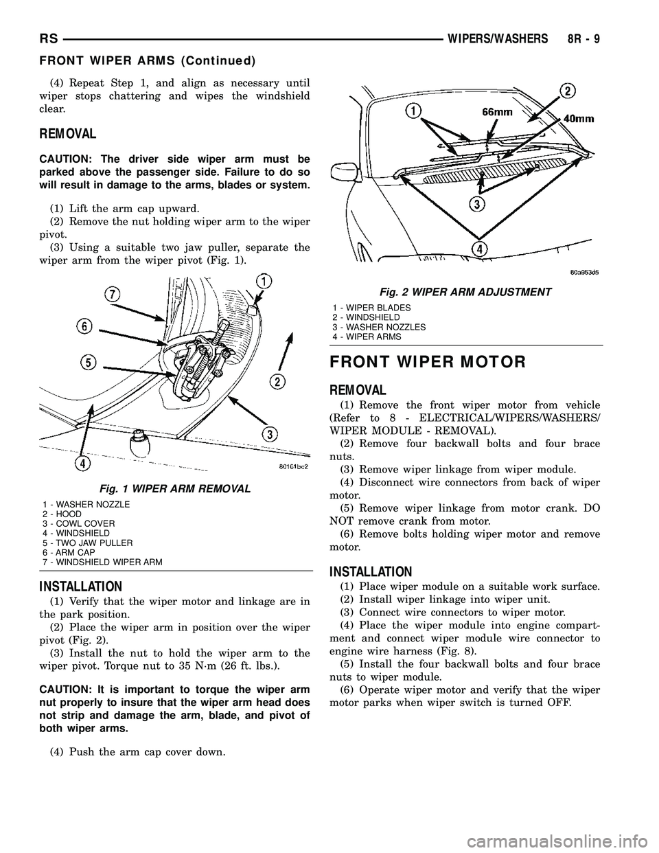
(3) Using a suitable two jaw puller, separate the
wiper arm from the wiper pivot (Fig. 1).
INSTALLATION
(1) Verify that the wiper motor and linkage are in
the park position.
(2) Place the wiper arm in position over the wiper
pivot (Fig. 2).
(3) Install the nut to hold the wiper arm to the
wiper pivot. Torque nut to 35 N´m (26 ft. lbs.).
CAUTION: It is important to torque the wiper arm
nut properly to insure that the wiper arm head does
not strip and damage the arm, blade, and pivot of
both wiper arms.
(4) Push the arm cap cover down.
FRONT WIPER MOTOR
REMOVAL
(1) Remove the front wiper motor from vehicle
(Refer to 8 - ELECTRICAL/WIPERS/WASHERS/
WIPER MODULE - REMOVAL).
(2) Remove four backwall bolts and four brace
nuts.
(3) Remove wiper linkage from wiper module.
(4) Disconnect wire connectors from back of wiper
motor.
(5) Remove wiper linkage from motor crank. DO
NOT remove crank from motor.
(6) Remove bolts holding wiper motor and remove
motor.
INSTALLATION
(1) Place wiper module on a suitable work surface.
(2) Install wiper linkage into wiper unit.
(3) Connect wire connectors to wiper motor.
(4) Place the wiper module into engine compart-
ment and connect wiper module wire connector to
engine wire harness (Fig. 8).
(5) Install the four backwall bolts and four brace
nuts to wiper module.
(6) Operate wiper motor and verify that the wiper
motor parks when wiper switch is turned OFF.
Fig. 1 WIPER ARM REMOVAL
1 - WASHER NOZZLE
2 - HOOD
3 - COWL COVER
4 - WINDSHIELD
5 - TWO JAW PULLER
6 - ARM CAP
7 - WINDSHIELD WIPER ARM
Fig. 2 WIPER ARM ADJUSTMENT
1 - WIPER BLADES
2 - WINDSHIELD
3 - WASHER NOZZLES
4 - WIPER ARMS
RSWIPERS/WASHERS8R-9
FRONT WIPER ARMS (Continued)
Page 697 of 2585
REAR WASHER PUMP MOTOR
REMOVAL
(1) Disconnect and isolate the battery negative
cable.
(2) Remove the engine fresh air housing inside the
engine compartment (Refer to 9 - ENGINE/AIR
INTAKE SYSTEM/AIR CLEANER HOUSING -
REMOVAL).
(3) Disconnect the washer hose at the in-line con-
nector forward of the cowl grille so that the in-line
connector remains with the washer hose from the
fresh air plenum.
(4) Disconnect the washer hose from the hose clip
located on the front fender side shield.
(5) Remove the filler tube screw.
(6) Hoist and support vehicle on hoist or jack
stands.
(7) Remove the right front wheel and tire assembly
(Refer to 22 - TIRES/WHEELS - REMOVAL).
(8) Disconnect the left right front wheelhouse
splash shield and move aside (Refer to 23 - BODY/
EXTERIOR/WHEELHOUSE SPLASH SHIELD -
REMOVAL).
(9) Drain washer fluid from the reservoir and into
a suitable clean container. This can be done by dis-
connecting the windshield washer hose from the
front (outboard) washer pump and allowing the
washer fluid to drain into a container through a tem-
porary jumper hose connected to the front washer
pump.
(10) Disconnect the electrical body harness connec-
tors to the washer pump motors and the fluid level
sensor. Slide the red lock on the connector to the
release position, then, depress the black tab and pull
the connector off the pump or sensor.
(11) Remove the two reservoir mounting screws.
(12) Disconnect the reservoir from the body mount
by raising the reservoir upward slightly and then
down so that the reservoir filler neck and front
washer hose pull through the opening in the front
fender side shield.
(13) Remove pump from reservoir by pulling pump
upper retention tab away from reservoir cavity and
then lifting pump up from mounting grommet. Do
not damage reservoir/pump sealing surface or punc-
ture reservoir during removal.
(14) Remove pump grommet and discard.
INSTALLATION
(1) Use new grommet when installing a new pump
assembly.
(2) Assure pump upper retention tab is pressed
into reservoir slot and that pump is rotated flat
against the reservoir and that pump connector is fac-
ing up in the fully seated position. Assure the pump
is aligned to and fully seated in the reservoir cavity.
(3) Push filler neck and front washer hose through
the opening in the front fender side shield. Connect
the reservoir to the body mount by lowering the res-
ervoir down.
(4) Install the two reservoir mounting screws.
Torque screws to 8.5 - 11.3 N´m (75 - 100 in. lbs.).
(5) Connect the electrical body harness connectors
to the washer pump motors and the fluid level sen-
sor. Slide the red lock on the connector to the closed
or locked position.
(6) Assure that washer hose is properly routed to
prevent pinching and possible inoperative washers.
(7) Connect the left right front wheelhouse splash
shield and move aside (Refer to 23 - BODY/EXTERI-
OR/WHEELHOUSE SPLASH SHIELD - INSTALLA-
TION).
(8) Install the right front wheel and tire assembly
(Refer to 22 - TIRES/WHEELS - INSTALLATION).
(9) lower vehicle from hoist or jack stands.
(10) Install the filler tube screw. Torque screw to
8.5 - 11.3 N´m (75 - 100 in. lbs.).
(11) Connect the washer hose to the hose clip
located on the front fender side shield.
(12) Connect the washer hose at the in-line con-
nector forward of the cowl grille.
(13) Install the engine fresh air housing inside the
engine compartment (Refer to 9 - ENGINE/AIR
INTAKE SYSTEM/AIR CLEANER HOUSING -
INSTALLATION).
(14) Connect the battery negative cable.
(15) Verify system operation.
REAR WIPER ARM
REMOVAL
(1) Remove arm nut cap.
(2) Remove wiper arm nut.
(3) Pull wiper from pivot by rocking back and
forth.
INSTALLATION
(1) Verify that wipers are in parked position.
(2) Position arm on pivot.
(3) Install wiper arm nut and torque to 20 N´m
(175 in. lbs.).
8R - 10 WIPERS/WASHERSRS
Page 698 of 2585
REAR WIPER MOTOR
REMOVAL
(1) Disconnect and isolate the battery negative
cable.
(2) Remove rear wiper arm. (Refer to 8 - ELEC-
TRICAL/WIPERS/WASHERS/REAR WIPER ARM -
REMOVAL) in this section.
(3) Open liftgate.
(4) Remove liftgate trim panel. (Refer to 23 -
BODY/DECKLID/HATCH/LIFTGATE/TAILGATE/
TRIM PANEL - REMOVAL).
(5) Disconnect wire connector from rear wiper
motor.
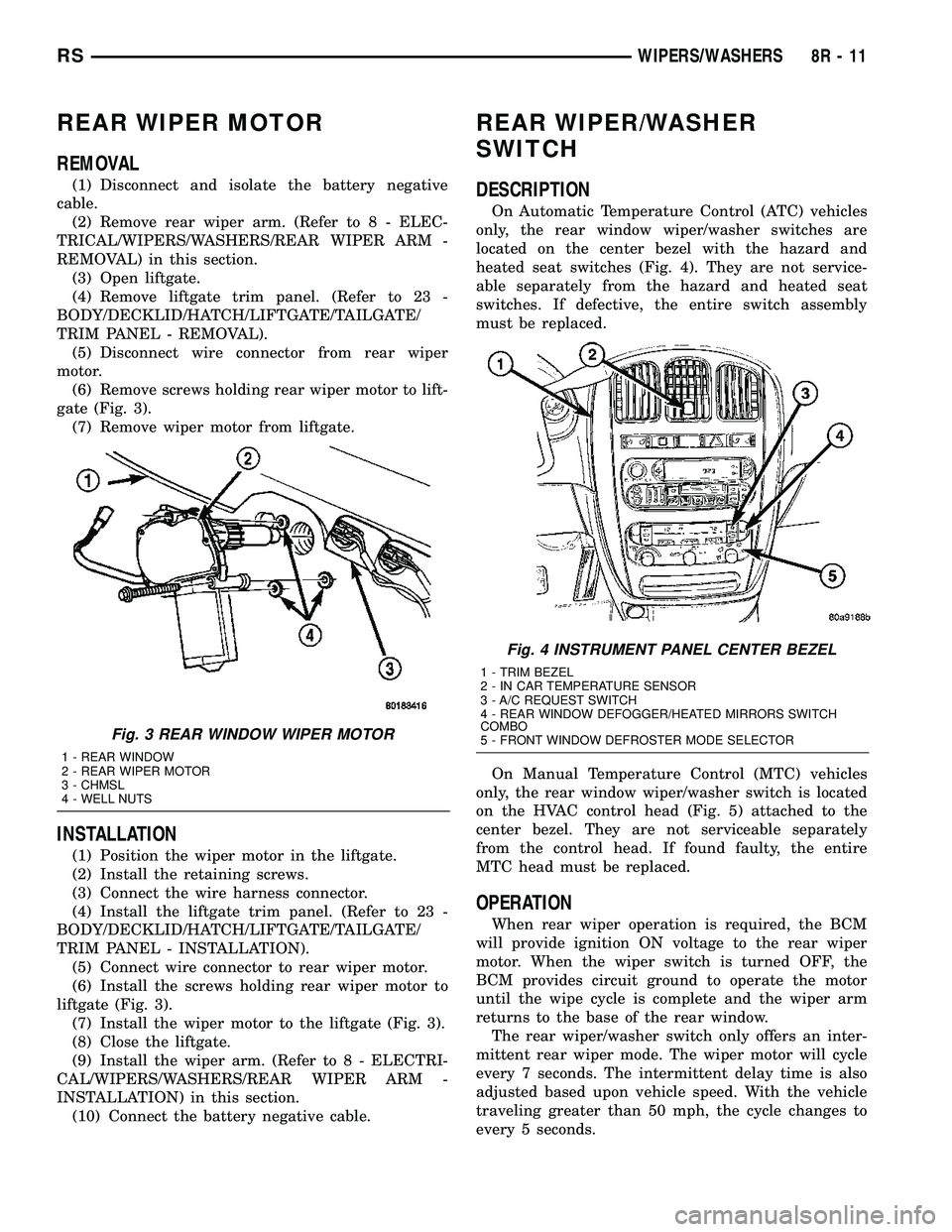
(6) Remove screws holding rear wiper motor to lift-
gate (Fig. 3).
(7) Remove wiper motor from liftgate.
INSTALLATION
(1) Position the wiper motor in the liftgate.
(2) Install the retaining screws.
(3) Connect the wire harness connector.
(4) Install the liftgate trim panel. (Refer to 23 -
BODY/DECKLID/HATCH/LIFTGATE/TAILGATE/
TRIM PANEL - INSTALLATION).
(5) Connect wire connector to rear wiper motor.
(6) Install the screws holding rear wiper motor to
liftgate (Fig. 3).
(7) Install the wiper motor to the liftgate (Fig. 3).
(8) Close the liftgate.
(9) Install the wiper arm. (Refer to 8 - ELECTRI-
CAL/WIPERS/WASHERS/REAR WIPER ARM -
INSTALLATION) in this section.
(10) Connect the battery negative cable.
REAR WIPER/WASHER
SWITCH
DESCRIPTION
On Automatic Temperature Control (ATC) vehicles
only, the rear window wiper/washer switches are
located on the center bezel with the hazard and
heated seat switches (Fig. 4). They are not service-
able separately from the hazard and heated seat
switches. If defective, the entire switch assembly
must be replaced.
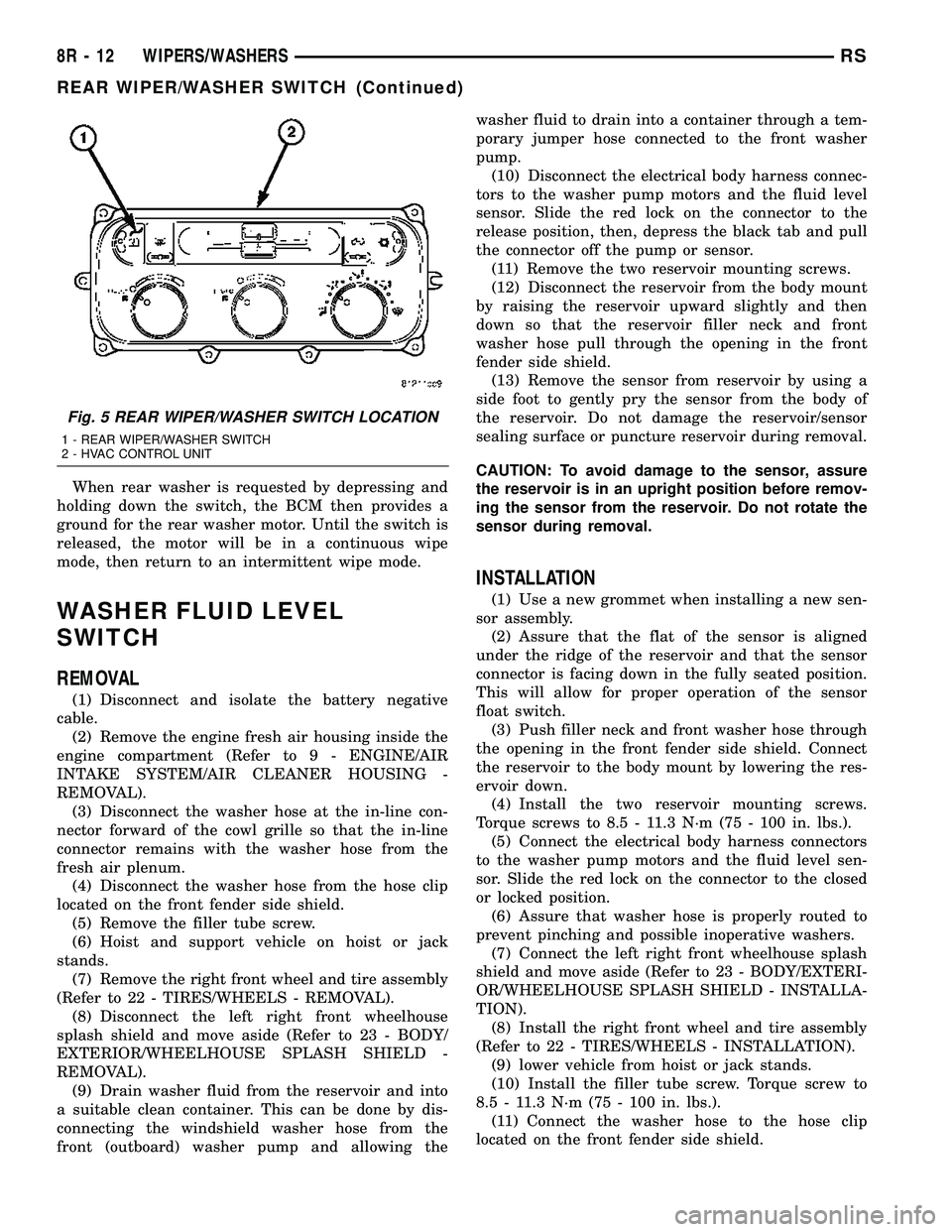
On Manual Temperature Control (MTC) vehicles
only, the rear window wiper/washer switch is located
on the HVAC control head (Fig. 5) attached to the
center bezel. They are not serviceable separately
from the control head. If found faulty, the entire
MTC head must be replaced.
OPERATION
When rear wiper operation is required, the BCM
will provide ignition ON voltage to the rear wiper
motor. When the wiper switch is turned OFF, the
BCM provides circuit ground to operate the motor
until the wipe cycle is complete and the wiper arm
returns to the base of the rear window.
The rear wiper/washer switch only offers an inter-
mittent rear wiper mode. The wiper motor will cycle
every 7 seconds. The intermittent delay time is also
adjusted based upon vehicle speed. With the vehicle
traveling greater than 50 mph, the cycle changes to
every 5 seconds.
Fig. 3 REAR WINDOW WIPER MOTOR
1 - REAR WINDOW
2 - REAR WIPER MOTOR
3 - CHMSL
4 - WELL NUTS
Fig. 4 INSTRUMENT PANEL CENTER BEZEL
1 - TRIM BEZEL
2 - IN CAR TEMPERATURE SENSOR
3 - A/C REQUEST SWITCH
4 - REAR WINDOW DEFOGGER/HEATED MIRRORS SWITCH
COMBO
5 - FRONT WINDOW DEFROSTER MODE SELECTOR
RSWIPERS/WASHERS8R-11
Page 699 of 2585
When rear washer is requested by depressing and
holding down the switch, the BCM then provides a
ground for the rear washer motor. Until the switch is
released, the motor will be in a continuous wipe
mode, then return to an intermittent wipe mode.
WASHER FLUID LEVEL
SWITCH
REMOVAL
(1) Disconnect and isolate the battery negative
cable.
(2) Remove the engine fresh air housing inside the
engine compartment (Refer to 9 - ENGINE/AIR
INTAKE SYSTEM/AIR CLEANER HOUSING -
REMOVAL).
(3) Disconnect the washer hose at the in-line con-
nector forward of the cowl grille so that the in-line
connector remains with the washer hose from the
fresh air plenum.
(4) Disconnect the washer hose from the hose clip
located on the front fender side shield.
(5) Remove the filler tube screw.
(6) Hoist and support vehicle on hoist or jack
stands.
(7) Remove the right front wheel and tire assembly
(Refer to 22 - TIRES/WHEELS - REMOVAL).
(8) Disconnect the left right front wheelhouse
splash shield and move aside (Refer to 23 - BODY/
EXTERIOR/WHEELHOUSE SPLASH SHIELD -
REMOVAL).
(9) Drain washer fluid from the reservoir and into
a suitable clean container. This can be done by dis-
connecting the windshield washer hose from the
front (outboard) washer pump and allowing thewasher fluid to drain into a container through a tem-
porary jumper hose connected to the front washer
pump.
(10) Disconnect the electrical body harness connec-
tors to the washer pump motors and the fluid level
sensor. Slide the red lock on the connector to the
release position, then, depress the black tab and pull
the connector off the pump or sensor.
(11) Remove the two reservoir mounting screws.
(12) Disconnect the reservoir from the body mount
by raising the reservoir upward slightly and then
down so that the reservoir filler neck and front
washer hose pull through the opening in the front
fender side shield.
(13) Remove the sensor from reservoir by using a
side foot to gently pry the sensor from the body of
the reservoir. Do not damage the reservoir/sensor
sealing surface or puncture reservoir during removal.
CAUTION: To avoid damage to the sensor, assure
the reservoir is in an upright position before remov-
ing the sensor from the reservoir. Do not rotate the
sensor during removal.
INSTALLATION
(1) Use a new grommet when installing a new sen-
sor assembly.
(2) Assure that the flat of the sensor is aligned
under the ridge of the reservoir and that the sensor
connector is facing down in the fully seated position.
This will allow for proper operation of the sensor
float switch.
(3) Push filler neck and front washer hose through
the opening in the front fender side shield. Connect
the reservoir to the body mount by lowering the res-
ervoir down.
(4) Install the two reservoir mounting screws.
Torque screws to 8.5 - 11.3 N´m (75 - 100 in. lbs.).
(5) Connect the electrical body harness connectors
to the washer pump motors and the fluid level sen-
sor. Slide the red lock on the connector to the closed
or locked position.
(6) Assure that washer hose is properly routed to
prevent pinching and possible inoperative washers.
(7) Connect the left right front wheelhouse splash
shield and move aside (Refer to 23 - BODY/EXTERI-
OR/WHEELHOUSE SPLASH SHIELD - INSTALLA-
TION).
(8) Install the right front wheel and tire assembly
(Refer to 22 - TIRES/WHEELS - INSTALLATION).
(9) lower vehicle from hoist or jack stands.
(10) Install the filler tube screw. Torque screw to
8.5 - 11.3 N´m (75 - 100 in. lbs.).
(11) Connect the washer hose to the hose clip
located on the front fender side shield.
Fig. 5 REAR WIPER/WASHER SWITCH LOCATION
1 - REAR WIPER/WASHER SWITCH
2 - HVAC CONTROL UNIT
8R - 12 WIPERS/WASHERSRS
REAR WIPER/WASHER SWITCH (Continued)
Page 700 of 2585

(12) Connect the washer hose at the in-line con-
nector forward of the cowl grille.
(13) Install the engine fresh air housing inside the
engine compartment (Refer to 9 - ENGINE/AIR
INTAKE SYSTEM/AIR CLEANER HOUSING -
INSTALLATION).
(14) Connect the battery negative cable.
(15) Verify system operation.
WASHER HOSES
REMOVAL
(1) Remove washer reservoir from vehicle (Refer to
8 - ELECTRICAL/WIPERS/WASHERS/WASHER
RESERVOIR - REMOVAL).
(2) Disconnect washer hose front the reservoir cav-
ity.
(3) Disconnect the washer hose from the reservoir
pump.
(4) Remove parts as necessary to replace washer
hose (engine compartment, interior components, etc.).
INSTALLATION
(1) Install parts as necessary to after replacing
washer hose (engine compartment, interior compo-
nents, etc.).
(2) Connect the washer hose to the reservoir
pump.
(3) Connect washer hose to the reservoir cavity.
(4) Install the washer reservoir into vehicle (Refer
to 8 - ELECTRICAL/WIPERS/WASHERS/WASHER
RESERVOIR - INSTALLATION).
WASHER RESERVOIR
REMOVAL
(1) Disconnect and isolate the battery negative
cable.
(2) Remove the engine fresh air housing inside the
engine compartment (Refer to 9 - ENGINE/AIR
INTAKE SYSTEM/AIR CLEANER HOUSING -
REMOVAL).
(3) Disconnect the washer hose at the in-line con-
nector forward of the cowl grille so that the in-line
connector remains with the washer hose from the
fresh air plenum.
(4) Disconnect the washer hose from the hose clip
located on the front fender side shield.
(5) Remove the filler tube screw.
(6) Hoist and support vehicle on hoist or jack
stands.
(7) Remove the right front wheel and tire assembly
(Refer to 22 - TIRES/WHEELS - REMOVAL).(8) Disconnect the left right front wheelhouse
splash shield and move aside (Refer to 23 - BODY/
EXTERIOR/WHEELHOUSE SPLASH SHIELD -
REMOVAL).
(9) Drain washer fluid from the reservoir and into
a suitable clean container. This can be done by dis-
connecting the windshield washer hose from the
front (outboard) washer pump and allowing the
washer fluid to drain into a container through a tem-
porary jumper hose connected to the front washer
pump.
(10) Disconnect the electrical body harness connec-
tors to the washer pump motors and the fluid level
sensor. Slide the red lock on the connector to the
release position, then, depress the black tab and pull
the connector off the pump or sensor.
(11) Remove the two reservoir mounting screws.
(12) Disconnect the reservoir from the body mount
by raising the reservoir upward slightly and then
down so that the reservoir filler neck and front
washer hose pull through the opening in the front
fender side shield.
INSTALLATION
(1) Push filler neck and front washer hose through
the opening in the front fender side shield. Connect
the reservoir to the body mount by lowering the res-
ervoir down.
(2) Install the two reservoir mounting screws.
Torque screws to 8.5 - 11.3 N´m (75 - 100 in. lbs.).
(3) Connect the electrical body harness connectors
to the washer pump motors and the fluid level sen-
sor. Slide the red lock on the connector to the closed
or locked position.
(4) Assure that washer is properly routed to pre-
vent pinching and possible inoperative washers.
(5) Connect the left right front wheelhouse splash
shield and move aside (Refer to 23 - BODY/EXTERI-
OR/WHEELHOUSE SPLASH SHIELD - INSTALLA-
TION).
(6) Install the right front wheel and tire assembly
(Refer to 22 - TIRES/WHEELS - INSTALLATION).
(7) lower vehicle from hoist or jack stands.
(8) Install the filler tube screw. Torque screw to 8.5
- 11.3 N´m (75 - 100 in. lbs.).
(9) Connect the washer hose to the hose clip
located on the front fender side shield.
(10) Connect the washer hose at the in-line con-
nector forward of the cowl grille.
(11) Install the engine fresh air housing inside the
engine compartment (Refer to 9 - ENGINE/AIR
INTAKE SYSTEM/AIR CLEANER HOUSING -
INSTALLATION).
(12) Connect the battery negative cable.
(13) Verify system operation.
RSWIPERS/WASHERS8R-13
WASHER FLUID LEVEL SWITCH (Continued)