belt DODGE TRUCK 1993 Service Repair Manual
[x] Cancel search | Manufacturer: DODGE, Model Year: 1993, Model line: TRUCK, Model: DODGE TRUCK 1993Pages: 1502, PDF Size: 80.97 MB
Page 1458 of 1502
•
HEATING
AND AIR
CONDITIONING
24 - 21 (a) Loosen both test hoses at the manifold gauge
set. Tighten the hoses as soon as the air is purged. (b) Loosen charging hose connection at manifold
gauge set. This will purge air from the charging
hose.
Tighten connection as soon as air is purged.
(9) With vehicle windows open and hood up, oper
ate engine at 1,300 RPM. (10) Place air conditioner control on A/C and place
the fan switch on high. (11) If necessary, block the condenser to maintain
a discharge pressure of 1 550-1 725 kPag (225-250
psig).
System must be charged through the evapora
tor suction service ports as follows:
(a) Slowly open the suction service gauge valve.
Meter flow of refrigerant by adjusting the suction service gauge valve so the pressure registered at
the suction service gauge does not exceed 345 kPag
COMPRESSOR
J
(50
psig). Keep refrigerant container upright.
(b) Add refrigerant gas until there is no foam visi
ble at the sight glass. As soon as all foam clears, note the weight registered on the refrigerant scale.
(c) Watch the refrigerant weighing scale and add
437 g (14 oz.) of refrigerant (equivalent to 1 can).
(d) Close the suction gauge valve.
CAUTION:
TOO
much
refrigerant
in the
system
can
cause
abnormally high discharge pressures. Care
must
be
used
so the
exact recommended amount
of
refrigerant
is
added
after
foam clears
in the
sight
glass.
(e) Close dispensing manifold valve. Remove test
hoses and adapters from the service ports of com
pressor and install protective caps at service ports.
RVICE (SD-709)
INDEX
page
Compressor
21
Compressor
Shaft Seal
.................... 25
The A/C system uses a 7 piston design Sanden SD-
709 compressor. Designated the SD-709, the compres
sor is mounted on the front right side of the engine
and is driven by a serpentine belt.
System lubrication is provided by 135cc ±15cc (4.6
cu. in. ±0.5 cu. in.) of 500 viscosity refrigerant oil.
The clutch used on the compressor consists of 3 ba
sic components:
(1) The pulley.
(2) The front plate. (3) The field coil.
The pulley and field coil are attached to the front
head of the compressor with snap rings. The hub is keyed to the compressor shaft and is retained on the
shaft with a self-locking nut. Special service tools are
required to remove and install the clutch plate on
the compressor shaft.
COMPRESSOR
REMOVAL
(1) Disconnect the negative cable from the battery.
(2) Disconnect the clutch lead wire.
(3) Remove the discharge and inlet (suction) ser
vice valves from the compressor. Plug or tape all the
openings.
(4) Refer to Group 7, Cooling System and remove
the drive belt(s). (5) Remove the bolts and lift the compressor from
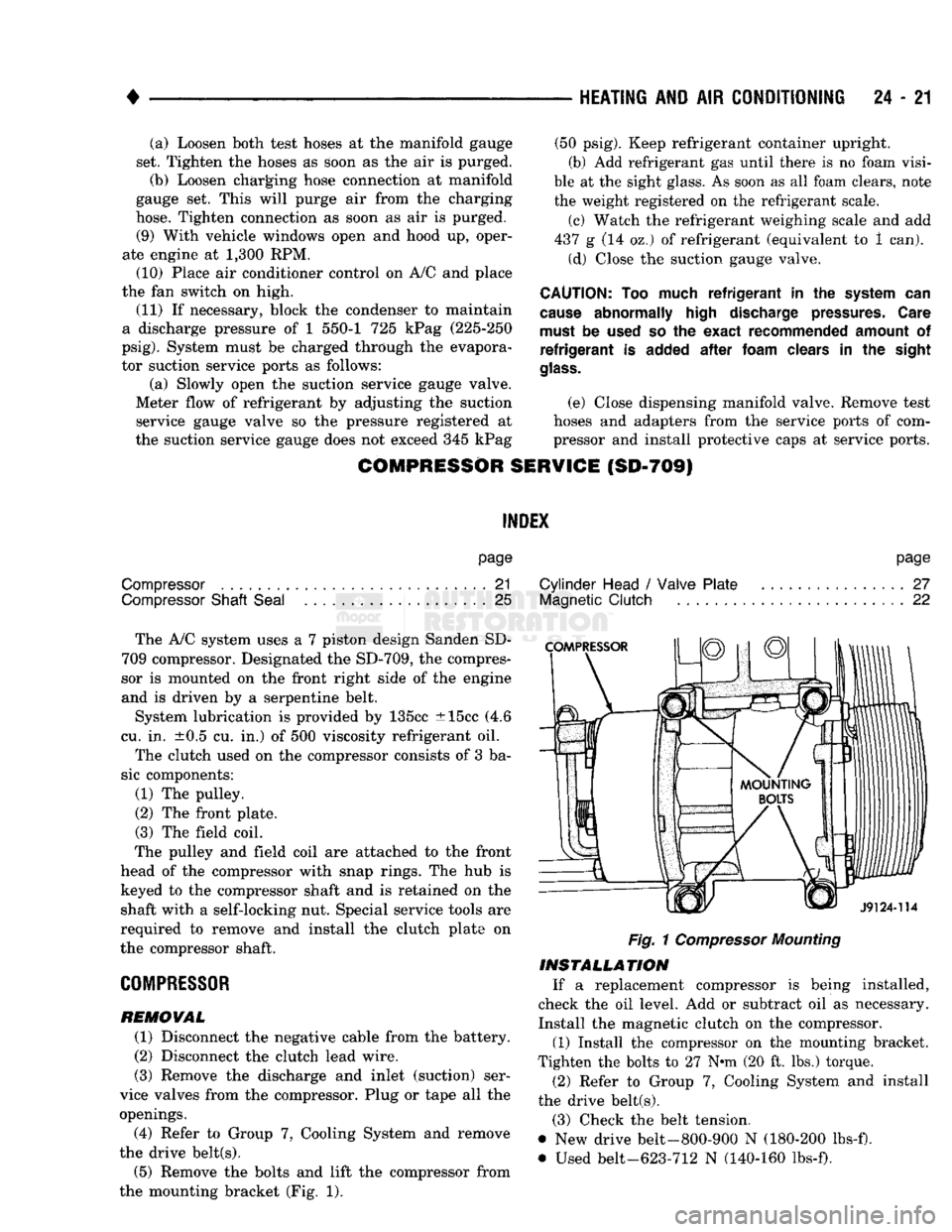
the mounting bracket (Fig. 1).
page
Cylinder Head
/
Valve Plate
27
Magnetic
Clutch
22
Fig.
1
Compressor
Mounting
INSTALLATION
If a replacement compressor is being installed,
check the oil level. Add or subtract oil as necessary.
Install the magnetic clutch on the compressor.
(1) Install the compressor on the mounting bracket.
Tighten the bolts to 27 N*m (20 ft. lbs.) torque.
(2) Refer to Group 7, Cooling System and install
the drive belt(s).
(3) Check the belt tension.
@ New drive belt-800-900 N (180-200 lbs-f).
• Used belt-623-712 N (140-160 lbs-f).
Page 1466 of 1502
HEATING
AND
AIR
CONDITIONING
24 - 29
CLIMATE CONTROL
SYSTEM
INDEX
page
Air Conditioner Distribution
and
Spot Cooler
Ducts-Center
. . 38
Air Conditioner Distribution
and
Spot Cooler
Ducts-Left Bi-Level
38
Air Conditioner Distribution
and
Spot Cooler
Ducts-Right
Bi-Level
38
Air
Outlet
Assemblies Right
Side
.............
38
Control Test
......
30
Defroster Duct
34
Electrical Controls
and
Circuits
30
Electronic Temperature Cycling Switch
37
Evaporator Control Unit
. . 34
GENERAL
INFORMATION
This
air
conditioner
is
designed specifically
for
con
ventional
cab
trucks with
the
heater-evaporator
package designed
to fit
under
the
instrument panel.
The system
is
manually controlled
by the
operator. Controls have been kept simple
for
ease
of
service and operation. In
the
blend
air
reheat
air
conditioning unit,
all
the
air
entering
the
system passes through
the
evap orator.
A
selected portion passes through
the
heater
core depending
on the
position
of the
blend
air
door.
The system controls
are
located
in the
center
of the
instrument panel within easy reach
of the
driver.
The combination electrical
and
vacuum switch con
trols
the
compressor clutch, mode
of
operation
and
blower. Modes
are Off, Max. A/C, A/C,
Vent, Heat and Defrost.
A
4-speed blower motor switch controls
the amount
of air
flow.
The
evaporator-heater pack age includes:
•
The
blower motor. • Intake duct with outside
air
recirculating door.
• Evaporator coil
• Heater core.
• Defroster discharge doors.
• Blower motor speed resistors.
• Vacuum harness.
• Vacuum actuators.
•
A/C air
outlets
to the
distribution ducts. Defrost, Heat,
A/C and
Vent modes automatically
supply
100%
outside
air.
The
air
distribution ducts supply
air
from
the
unit
to
4
panel mounted, fully directional, outlets.
The
faceplate
has 2
outlets
and 2 are
snapped into
the
panel
on the
right side. Satisfactory performance
of the air
conditioning
and heating system
is
dependent upon correct opera
tion
and
adjustment
of all
operating controls.
The in
spections, tests
and
adjustments should
be
used
to
locate
the
cause
of a
malfunction.
The
tests
in
this
page
Evaporator Heater Assembly
36
Expansion
(H)
Valve
37
Faceplate
32
General Information
. 29
Heater Assembly
. 33
Heater Control
32
Louver
Assemblies
39
Operation
of All
Controls
29
Resistor
Block
33
Temperature
and
Mode Control Cables
. 32
Vacuum
Actuators
36
Vacuum
Controls
and
Circuits
30
manual have been arranged
in a
logical sequence
that
has
proved
to be the
surest
and
shortest route
to
accurate diagnosis.
It is
recommended that they
be
followed
and
performed
in the
order they
are
pre sented.
OPERATION
OF ALL
CONTROLS
Operation must
be
tested
as
described
in the
fol
lowing sequence: (1) Inspect, test,
and
adjust compressor drive belt.
(2) Start engine
and
adjust engine speed
to 1,300
RPM.
Use a
reliable tachometer. (3) Move temperature control lever
to
Cool position
and mode lever
to A/C
position. (4)
The
inlet
air
door should
be
open
to
outside
air.
Open vehicle windows. (5) Test
the
blower operation
at all 4
speed posi
tions.
If the
blower does
not
operate correctly refer
to
Electrical Controls
and
Circuit. Leave
the
blower switch
in the
HIGH position.
(6)
The
compressor should
be
running
and the air
conditioning system
in
operation. In addition
to the six
position push button selector,
the
A/C
Heater control consists
of:
TEMPERATURE LEVER-Controls
the
tempera-.
ture
of the
discharge
air in all
modes except
MAX
A/C
and Off
when
the
vacuum operated water valve is closed. Moving
the
lever
to the
left provides cooler
air
and
moving
it to the
right provides warmer
air.
BLOWER SWITCH-The system blower
can be op
erated
at 4
speeds.
•
LOW at the
bottom. • MEDIUM
1 at the
lower center.
• MEDIUM
2 at the
upper center.
• HIGH
at the top
switch position. The blower will
be on and
operating
at the
speed
selected,
in all
push button positions except
Off.
AIR DIRECTIONAL VANES-Air
is
delivered
through
4
panel outlets.
The 4
outlets
are
adjustable
Page 1467 of 1502
24 - 30
HEATING
AND AIR
CONDITIONING
•
up,
down or to either side and can be shut off by
pushing the vanes up. Floor air is delivered through
the lower outlets.
VACUUM CONTROLS
AND
CIRCUITS
For an explanation of the vacuum and electrical
logic that controls the operation of the unit (Fig. 1
and Control Chart). MODES—The vacuum and electrical logic is deter
mined by the push button switch. The vacuum por
tion of the switch controls the water valve and
positions all doors in the unit except the blend air
door. The electrical portion of the switch controls the compressor and blower operation. The following is a
breakdown of the vacuum and electrical logic for each mode. Refer to Control Chart in this section.
OFF Vacuum application is as indicated in Fig. 1. The
inlet air door is closed to outside, open to recirculat
ing air. The mode door is in the A/C position. The
Heat/Defrost door is in the Heat position. The heater core coolant flow is
shut-off.
No air flows through the unit and the compressor
is idle because the blower and compressor clutch cir
cuits are open.
MAX A/C All of the doors are in the same position as they
are in Off. The Max. A/C mode merely closes the
electrical circuits to the blower motor and the com
pressor clutch. This mode is recommended for initial cool down, extreme outside humidity or high ambient
temperature.
A/C
This mode is recommended for use after the vehicle
has been cooled to the desired temperature. The vac
uum application at the outside-recirculating air door actuator is transferred to the rod side. This moves
the door away from the outside-air inlet and closes
the recirculating inlet. The water valve is open. All
other vacuum applications and door positions are the
same for the Max. A/C position. The blower motor and compressor are on.
VENT The vacuum circuit remains the same as in the
A/C position but the compressor clutch electrical cir
cuit is opened, preventing the compressor from oper ating. The blower motor is used to force outside air
into the passenger compartment through the A/C
outlets in the instrument panel.
HEAT
In the Heat mode the outside air door is open same
as A/C mode. Vacuum is applied to the top side of the air condi
tioning door actuator. This will close off the passage
to the air conditioning distribution duct and open the
passage to the heater/defroster duct. Since the heat er-defroster door is in the heat position, the full flow
of heated air goes through the heater outlets. A
small amount of heated air will bleed through the
defroster outlets. The water valve is open, the blower
switch is activated and the compressor is off.
DEFROST When the defrost mode is selected all conditions
are the same as for heater operation, except that no
vacuum is applied to the defrost door actuator. The defrost door is spring loaded to the defrost position.
The door opens the defroster outlets and partially closes off the heater outlets. The heater outlets are
left open far enough to direct about 30 percent of the
air to the floor. The other 70% is defrost air directed
to the windshield area. The compressor clutch will be engaged.
ELECTRICAL CONTROLS AND CIRCUITS
The electrical feed for the air conditioning circuit is
from 2 fuses in the fuse block. A 20 ampere fuse pro
tects the compressor clutch circuit, and a 30 ampere fuse protects the blower motor control circuit.
CONTROL TEST
Test operation of controls in the following manner.
(1) Inspect compressor drive belt. Adjust, if neces
sary. (2) Start engine. (3) Move temperature lever to extreme left (cool)
position. (4) Push A/C button.
(5)
Refer to Control Chart. Check position of doors,
operation of compressor clutch, blower motor and wa
ter valve. The water valve is open when there is no
vacuum to valve. (6) Check blower switch by moving it to all 4 posi
tions and noting air flow change. In case of malfunc
tion refer to Electrical Control Circuit. (7) Check operation of blend air door by moving
temperature lever from full warm toward cool posi
tion. Discharge air temperature should change with lever movement if the engine coolant is warm. (8) Repeat steps 5 and 6 in each push-button posi
tion. If actuation of the doors is slow or incomplete,
check for mechanical misalignment, binding or vac uum leaks. The air conditioning door has a seven
second vacuum delay in mode switching from Off,
Max A/C, A/C, or Vent to Heat or Defrost. Check
temperature control cable for correct adjustment.
Page 1492 of 1502
•
EMISSION
CONTROL
SYSTEMS
25 - 15
AIR INJECTION SYSTEM—5.9L
HDC-GAS
ENGINE
INDEX
page
Air
Injection
Pump
15
Check
Valve—Air
Injection
Tube 16 General
Information
page
. . 15
GENERAL
INFORMATION
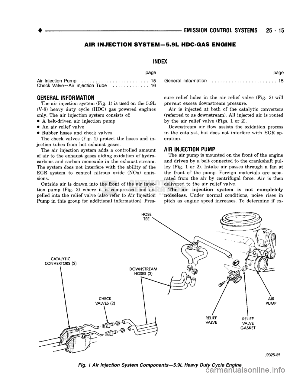
The air injection system (Fig. 1) is used on the 5.9L
(V-8) heavy duty cycle (HDC) gas powered engines
only. The air injection system consists of:
• A belt-driven air injection pump • An air relief valve
• Rubber hoses and check valves The check valves (Fig. 1) protect the hoses and in
jection tubes from hot exhaust gases. The air injection system adds a controlled amount
of air to the exhaust gases aiding oxidation of hydro
carbons and carbon monoxide in the exhaust stream.
The system does not interfere with the ability of the EGR system to control nitrous oxide (NOx) emis
sions.
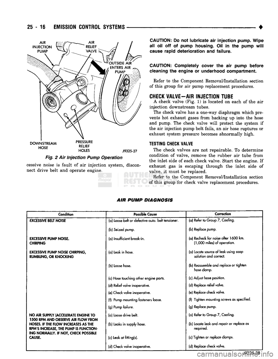
Outside air is drawn into the front of the air injec
tion pump (Fig. 2) where it is compressed and ex
pelled into the relief valve (also refer to Air Injection Pump in this group for additional information). Pres sure relief holes in the air relief valve (Fig. 2) will
prevent excess downstream pressure.
Air is injected at both of the catalytic convertors
(referred to as downstream). All injected air is routed
by the air relief valve (Figs. 1 or 2).
Downstream air flow assists the oxidation process
in the catalyst, but does not interfere with EGR op eration.
AIR INJECTION PUMP
The air pump is mounted on the front of the engine
and driven by a belt connected to the crankshaft pul
ley (Fig. 1 or 2). Intake air passes through a fan at
the front of the pump. Foreign materials are sepa rated from the air by centrifugal force. Air is then
delivered to the air relief valve.
The air injection system is not completely
noiseless. Under normal conditions, noise rises in
pitch as engine speed increases. To determine if ex-
HOSE
TEE
CATALYTIC
CONVERTORS
(2)
AIR
PUMP
RELIEF
VALVE
GASKET
J9325-35
Fig.
1 Air injection
System
Components—5.9L
Heavy
Duty
Cycle
Engine
Page 1493 of 1502
25 - 16
EMISSION
CONTROL
SYSTEMS
•
DOWNSTREAM
dciicc
HOSE
RELIEF
HOLES
J9325-37
Fig.
2 Air Injection
Pump
Operation cessive noise is fault of air injection system, discon
nect drive belt and operate engine.
CAUTION:
Do not lubricate air injection pump. Wipe
all oil off of pump
housing.
Oil in the pump
will
cause
rapid deterioration and failure.
CAUTION:
Completely cover the air pump before
cleaning
the engine or underhood compartment. Refer to the Component Removal/Installation section
of this group for air pump replacement procedures.
CHECK
VALVE—AIR
INJECTION
TUBE
A check valve (Fig. 1) is located on each of the air
injection downstream tubes. The check valve has a one-way diaphragm which pre
vents hot exhaust gases from backing up into the hose and pump. The check valve will protect the system if
the air injection pump belt fails, an air hose ruptures or exhaust system pressure becomes abnormally high.
TESTING
CHECK
VALVE
The check valves are not repairable. To determine
condition of valve, remove the rubber air tube from
the inlet side of each check valve. Start the engine. If
exhaust gas is escaping through the inlet side of
valve, it must be replaced.
Refer to the Component Removal/Installation section
of this group for check valve replacement procedures.
AIR
PUMP
DIAGNOSIS
Condition
Possible
Cause
Correction
EXCESSIVE
BELT
NOISE
(a)
Loose
belt
or defective auto,
belt
tensioner. (a) Refer to
Group
7,
Cooling.
(b) Seized pump. (b) Replace pump.
EXCESSIVE
PUMP
NOISE.
CHIRPING
(a) Insufficient break-in.
(a) Recheck for
noise
after
1600 km.
(1,000
miles) of operation.
EXCESSIVE
PUMP
NOISE CHIRPING,
RUMBUNG, OR KNOCKING (a) Leak in
hose.
(a) Locate
source
of leak
using
soap
solution
and correct.
(b)
Loose
hose.
(b)
Reassemble
and replace or tighten
hose
clamp.
(c)
Hose
touching other engine parts. (c) Adjust
hose
position.
(d) Relief valve inoperative. (d) Replace
relief
valve.
(e) Check valve inoperative. (e) Replace check valve.
(f)
Pump
mounting fasteners
loose.
(f) Tighten mounting
screws
as specified.
(g)
Pump
failure.
(g)
Replace pump.
NO AIR SUPPLY (ACCELERATE ENGINE TO 1500 RPM AND OBSERVE AIR
FLOW
FROM
HOSES.
IF THE
FLOW
INCREASES
AS
THE
RPM'S
INCREASE, THE
PUMP
IS
FUNCTION
ING NORMALLY. IF NOT, CHECK POSSIBLE
CAUSE.
(a)
Loose
drive belt.
(b)
Leaks
in
supply
hose.
(c) Leak at fitting(s). (a) Refer to
Group
7,
Cooling.
(b) Locate leak and repair or replace as required.
(c) Tighten or replace
clamps.
(d) Check valve inoperative. (d) Replace check valve.
J9325-38
Page 1494 of 1502

•
EMISSION
CONTROL SYSTEMS
25 - 17
COMPONENT REMOVAL/INSTALLATION
INDEI
page
Air
Filter/Filter
Housing—Diesel Engines
17
Air
Filter/Filter
Housing—Gas Engines
17
Air
Injection
Pump
17
Air
Injection
Pump Relief Valve
18
Check
Valve—Air
Injection
Tube
18
Coolant Temperature
Sensor
. 18
EGR
Tube—Gas Powered Engines
19
EGR
Valve
19
AIR FILTER/FILTER HOUSING-GAS ENGINES
REMOVAL/INSTALLATION Remove crankcase breather/filter hose at side of air
filter housing. Remove wingnut (Fig. 1) and remove
housing from engine. Check condition of gasket at
throttle body and replace as necessary. To replace air filter element only: Remove wingnut
and air filter housing cover (Fig. 1). Clean inside of
housing before replacing filter. Housing removal is not necessary for filter replacement.
^
WING NUT
COVER
:
GASKET
| I
MOUNTING
STUD
Fig.
1 Air
Filter
Housing—Gas
Powered
Engines—Typical
page
Electric
EGR Transducer (EET)
20
EVAP
Canister
20
EVAP
Canister Purge Solenoid
20
Fuel Tank
Filler
Tube
Cap . 21
Oxygen
(02)
Sensor
21
Powertrain Control Module (PCM)
21
Pressure
Relief/Rollover Valve
21
If housing-to-throttle body mounting stud is being
installed, tighten to 10 N»m (90 in. lbs.) torque. In stall housing to engine and tighten wingnut to 1.5
N»m (15 in. lbs.) torque.
AIR FILTER/FILTER HOUSING-DIESEL ENGINES
REMO
VAL/INSTALLA
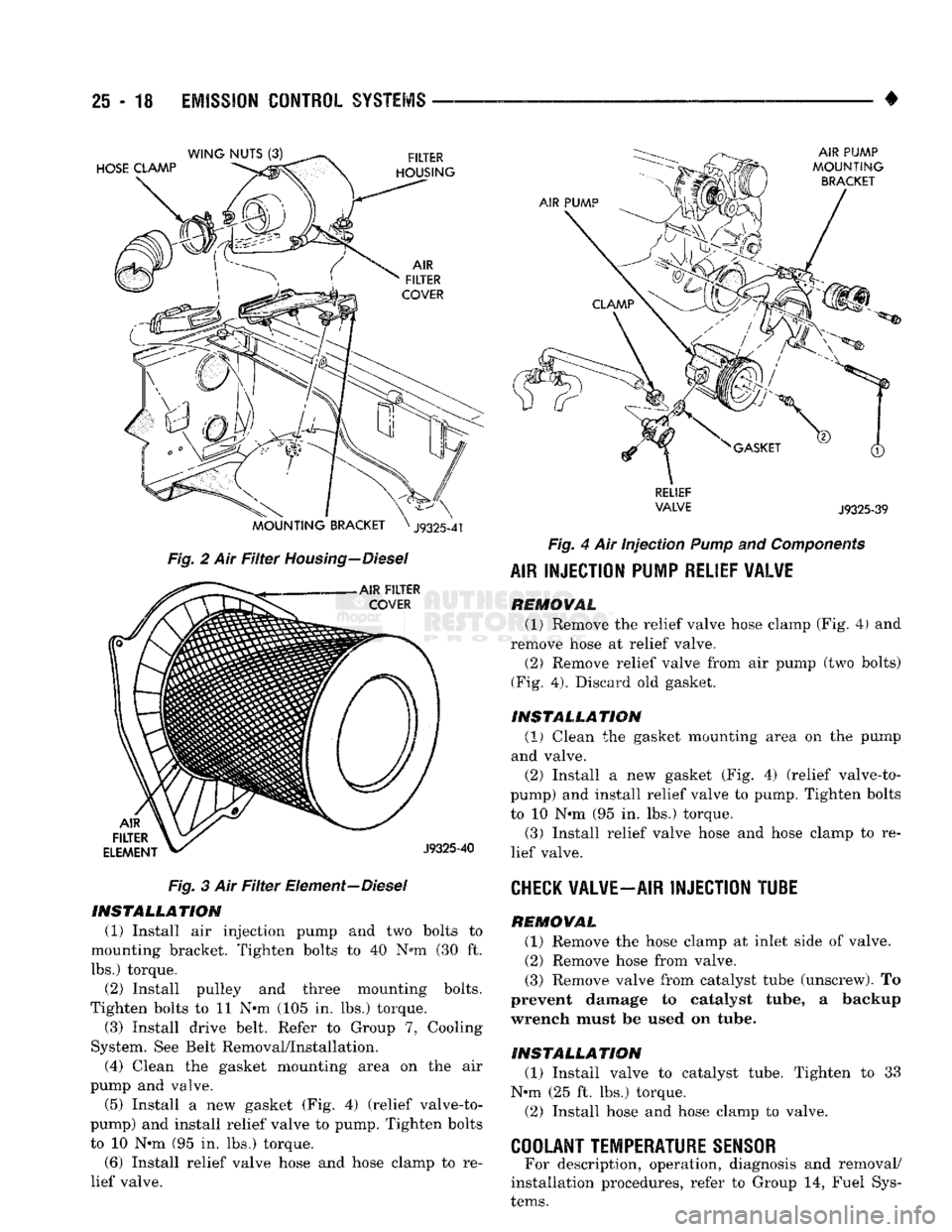
TION Remove the hose clamp at air filter housing (Fig.
2).
Remove mounting nuts and remove air filter
housing from vehicle.
To replace air filter element only: Remove hose clamp
and hose at air filter housing inlet tube. Remove three
wingnuts and air filter housing cover (Figs. 2 and 3). Clean inside of housing before replacing filter. Housing
removal is not necessary for filter replacement.
When installing a new air filter element, push el
ement into cover. Be sure it is pushed into tabs in
back of filter housing. Install wing nuts.
If housing had been removed, install mounting
nuts and tighten to 10 N»m (95 in. lbs.) torque.
AIR INJECTION PUMP
REMOVAL (1) Remove the relief valve hose clamp (Fig. 4) and
remove hose at relief valve.
(2) Remove relief valve from air pump (two bolts)
(Fig. 4). (3) Loosen (but do not remove at this time) the
three air pump pulley mounting bolts (number 2—figure 4).
(4) Relax the automatic belt tensioner and remove
the engine accessory drive belt. Refer to Group 7, Cooling System. See Belt Removal/Installation.
(5) Remove the three air pump pulley bolts and re
move pulley from pump.
(6) Remove the two air pump mounting bolts
(number
1—figure
4) and remove pump from mount
ing bracket.
Page 1495 of 1502
25
- 18
EMISSION
CONTROL
SYSTEMS
Fig. 2 Air Filter Housing—Diesel Fig. 3 Air Filter Element—Diesel INSTALLATION
(1) Install air injection pump and two bolts to
mounting bracket. Tighten bolts to 40 N*m (30 ft.
lbs.) torque. (2) Install pulley and three mounting bolts.
Tighten bolts to 11 N*m (105 in. lbs.) torque.
(3) Install drive belt. Refer to Group 7, Cooling
System. See Belt Removal/Installation.
(4) Clean the gasket mounting area on the air
pump and valve. (5) Install a new gasket (Fig. 4) (relief valve-to-
pump) and install relief valve to pump. Tighten bolts to 10 N*m (95 in. lbs.) torque.
(6) Install relief valve hose and hose clamp to re
lief valve. •
RELIEF
VALVE
J9325-39
Fig. 4 Air Injection
Pump
and
Components
AIR
INJECTION PUMP RELIEF VALVE REMOVAL
(1) Remove the relief valve hose clamp (Fig. 4) and
remove hose at relief valve.
(2) Remove relief valve from air pump (two bolts)
(Fig. 4). Discard old gasket.
INSTALLATION (1)
Clean the gasket mounting area on the pump
and valve. (2) Install a new gasket (Fig. 4) (relief valve-to-
pump) and install relief valve to pump. Tighten bolts
to 10 N*m (95 in. lbs.) torque. (3) Install relief valve hose and hose clamp to re
lief valve.
CHECK
VALVE—AIR INJECTION TUBE REMOVAL
(1) Remove the hose clamp at inlet side of valve.
(2) Remove hose from valve.
(3) Remove valve from catalyst tube (unscrew). To
prevent damage to catalyst tube, a backup
wrench must be used on tube.
INSTALLATION
(1) Install valve to catalyst tube. Tighten to 33
N«m (25 ft. lbs.) torque.
(2) Install hose and hose clamp to valve.
COOLANT TEMPERATURE SENSOR
For description, operation, diagnosis and removal/
installation procedures, refer to Group 14, Fuel Sys
tems.
Page 1500 of 1502
COMPONENT AND SYSTEM INDEX
Name
Group-page
AUDIO
SYSTEMS
8F-1
SERVICE
PROCEDURES 8F-7
TEST PROCEDURES 8F-2
BATTERY/STARTER/GENERATOR SERVICE 8B-1 BATTERY SERVICE PROCEDURES 8B-1
GENERATOR SERVICE 8B-6
SPECIFICATIONS 8B-9
STARTER SERVICE PROCEDURES 8B-4
BODY COMPONENTS 23-1 CAB/BODY INTERIOR COMPONENTS
23-35
DOORS
23-21
EXTERIOR COMPONENTS 23-1
FIXED GLASS
23-29
PAINT
CODE CHART
23-54
REFINISHING PROCEDURES
23-54
BRAKES
5-1 BENDIX DISC BRAKE 5-37 BRAKE ADJUSTMENTS-BRAKE BLEEDING 5-7
BRAKE DIAGNOSIS 5-3
CHRYSLER
DISC BRAKE 5-27 DRUM BRAKES—ELEVEN INCH 5-46
DRUM BRAKES-TWELVE INCH 5-50
GENERAL INFORMATION 5-1 MASTER CYLINDER—COMBINATION VALVE-BRAKE
LINES 5-10
PARKING BRAKES 5-56
POWER BRAKE BOOSTER-BRAKE PEDAL 5-20 POWER BRAKE VACUUM PUMP-DIESEL ENGINE. . 5-22
REAR
WHEEL ANTILOCK
(RWAL)
BRAKES 5-59
SPECIFICATIONS 5-65
CHIME/BUZZER WARNING
SYSTEMS
8U-1
CLUTCH 6-1 CLUTCH DIAGNOSIS 6-2 CLUTCH SERVICE 6-11
COOLING SYSTEM 7-1
DIAGNOSIS 7-4
ENGINE ACCESSORY DRIVE BELTS 7-40
ENGINE BLOCK HEATERS 7-48
SERVICE
PROCEDURES 7-15 SPECIFICATIONS 7-49
ELECTRICAL 8A-1 BATTERY TEST PROCEDURES 8A-2
ENGINE STARTER MOTOR TEST PROCEDURES.... 8A-9
GENERAL INFORMATION 8A-1
GENERATOR TEST PROCEDURES ON VEHICLE . . . 8A-13
GROUP INDEX 8A-1
SPECIFICATIONS 8A-18
BATTERY/STARTING/CHARGING
SYSTEMS
DIAGNOSTICS 8A-1
EMISSION
CONTROL
SYSTEMS.
25-1 AIR INJECTION SYSTEM—5.9L HDC-GAS ENGINE . 25-15 COMPONENT REMOVAL/INSTALLATION 25-17 EVAPORATIVE EMISSION CONTROLS 25-6
EXHAUST EMISSION CONTROLS 25-10
GENERAL INFORMATION 25-1
ENGINES 9-1 3.9L ENGINE SERVICE PROCEDURES 9-17 5.2L ENGINE SERVICE PROCEDURES 9-47
5.9L (DIESEL) ENGINE SERVICE PROCEDURES . . . 9-107
Name
Group-page
5.9L ENGINE SERVICE PROCEDURES 9-77 ENGINE DIAGNOSIS 9-5
STANDARD SERVICE PROCEDURES 9-1
EXHAUST SYSTEM AND INTAKE MANIFOLD 11-1
EXHAUST SYSTEM DIAGNOSIS 11-3
GENERAL INFORMATION 11-1
SERVICE
PROCEDURES (DIESEL ENGINES) 11-17
SERVICE
PROCEDURES (GASOLINE ENGINES) 11-4
SPECIFICATIONS 11-27
FRAME AND BUMPERS 13-1 ATTACHED COMPONENTS 13-30
BUMPERS
13-1
FRAME 13-20
SNOW PLOW 13-3
FRONT SUSPENSION AND AXLE 2-1 FRONT SUSPENSION—2WD VEHICLES 2-7
FRONT SUSPENSION—4WD VEHICLES 2-14 FRONT WHEEL ALIGNMENT 2-3
GENERAL INFORMATION 2-1 MODEL 44 FRONT AXLE 2-17
MODEL 60 FRONT AXLE 2-49
TORQUE SPECIFICATIONS 2-75
FUEL SYSTEM 14-1 ACCELERATOR PEDAL AND THROTTLE CABLE . . . 14-25
DIESEL
FUEL INJECTION—COMPONENT DESCRIPTION/SYSTEM OPERATION 14-76
DIESEL
FUEL INJECTION-GENERAL DIAGNOSIS. . 14-88
DIESEL
FUEL INJECTION-SERVICE
PROCEDURES
14-106
FUEL DELIVERY SYSTEM-EXCEPT DIESEL 14-3
FUEL DELIVERY-DIESEL ENGINE 14-15 FUEL TANKS 14-20
GENERAL INFORMATION 14-1 MULTI-PORT FUEL INJECTION (MPI)-COMPONENT DESCRIPTION/SYSTEM OPERATION-EXCEPT
DIESEL
14-29
MULTI-PORT FUEL INJECTION
(MPlj-COMPONENT
REMOVAL/INSTALLATION-EXCEPT DIESEL .... 14-64
MULTI-PORT FUEL INJECTION (MPI)—GENERAL DIAGNOSIS-EXCEPT DIESEL 14-43
SERVICE
ADJUSTMENTS-DIESEL
14-122
SPECIFICATIONS
14-123
HEATING AND AIR CONDITIONING 24-1 CLIMATE CONTROL SYSTEM
24-29
COMPRESSOR
SERVICE
(SD-709)
24-21 DIAGNOSTIC PROCEDURES 24-3
GENERAL INFORMATION 24-1 REFRIGERANT SYSTEM SERVICE PROCEDURES . . 24-17
TORQUE SPECIFICATIONS
24-39
HORNS 8G-1
SERVICE
PROCEDURES 8G-3
TEST PROCEDURES 8G-1
IGNITION
SYSTEMS
8D-1 COMPONENT IDENTIFICATION/SYSTEM OPERATION. 8D-1
COMPONENT REMOVAL/INSTALLATION 8D-18 DIAGNOSTICS/SERVICE PROCEDURES 8D-7
IGNITION
SWITCH
8D-25
SPECIFICATIONS
8D-28
INSTRUMENT PANEL AND GAUGES 8E-1