belt DODGE TRUCK 1993 Service Manual Online
[x] Cancel search | Manufacturer: DODGE, Model Year: 1993, Model line: TRUCK, Model: DODGE TRUCK 1993Pages: 1502, PDF Size: 80.97 MB
Page 696 of 1502
(7) Install vibration damper.
(8) Install fuel lines (refer to Group 14, Fuel Sys
tem).
(9) Install water pump and housing assembly us
ing new gaskets (refer to Group 7, Cooling System).
Tighten bolts to 41 N-m (30 ft. lbs.) torque.
(10) Install power steering pump (refer to Group
19,
Steering).
(11) Install the serpentine belt (refer to Group 7,
Cooling System). (12) Install the cooling system fan. Tighten the
bolts to 23 N-m (17 ft. lbs.) torque. (13) Position the fan shroud and install the bolts.
Tighten the bolts to 11 N-m (95 in. lbs.) torque. (14) Fill cooling system (refer to Group 7, Cooling
System for the proper procedure). (15) Connect the negative cable to the battery.
FRONT CRANKSHAFT
OIL
SEAL
REPLACEMENT
The oil seal can be replaced without removing the
timing chain cover provided the cover is not mis aligned. (1) Disconnect the negative cable from the battery.
(2) Remove vibration damper.
(3) If front seal is suspected of leaking, check front
oil seal alignment to crankshaft. The seal installa
tion/alignment tool 6635, should fit with minimum interference. If tool does not fit, the cover must be re
moved and installed properly. (4) Place a suitable tool behind the lips of the oil
seal to pry the oil seal outward. Be careful not to
damage the crankshaft seal surface of cover. (5) Place the smaller diameter of the oil seal over
Front Oil Seal Installation Tool 6635 (Fig. 6). Seat
the oil seal in the groove of the tool. (6) Position the seal and tool onto the crankshaft
(Fig. 7). (7) Using the vibration damper bolt, tighten the
bolt to draw the seal into position on the crankshaft (Fig. 8). (8) Remove the vibration damper bolt and seal in
stallation tool. (9) Install the vibration damper.
(10) Connect the negative cable to the battery.
CAMSHAFT
This procedure requires that the engine is removed
from the vehicle. The camshaft has an integral oil pump and distrib
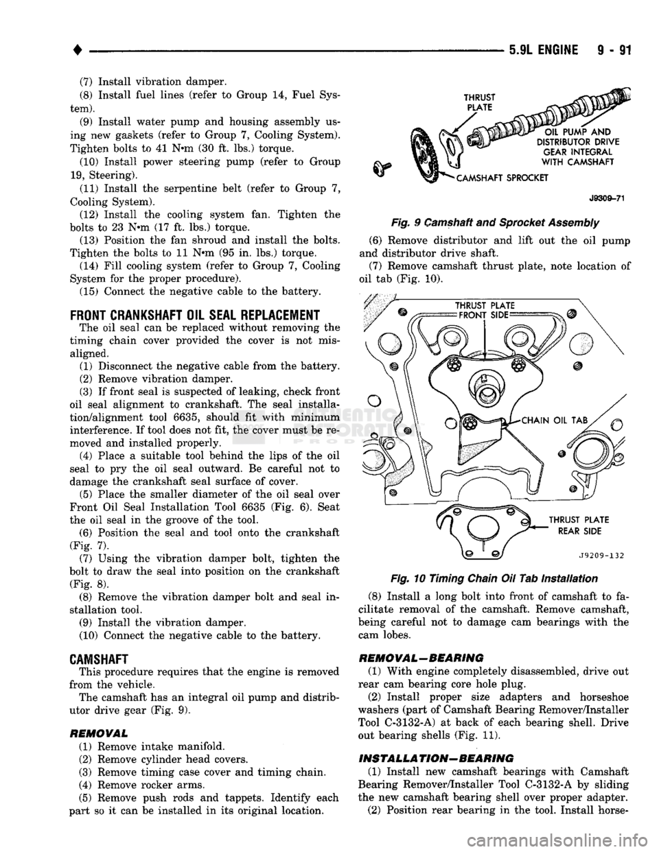
utor drive gear (Fig. 9).
REMOVAL
(1) Remove intake manifold.
(2) Remove cylinder head covers.
(3) Remove timing case cover and timing chain.
(4) Remove rocker arms.
(5) Remove push rods and tappets. Identify each
part so it can be installed in its original location.
THRUST
PLATE
OIL PUMP
AND
DISTRIBUTOR DRIVE
GEAR
INTEGRAL
WITH
CAMSHAFT
•CAMSHAFT SPROCKET
J8309-71
Fig.
9 Camshaft and
Sprocket Assembly
(6) Remove distributor and lift out the oil pump
and distributor drive shaft. (7) Remove camshaft thrust plate, note location of
oil tab (Fig. 10).
THRUST PLATE
REAR
SIDE
J9209-132
Fig.
10 Timing
Chain
Oil Tab
Installation
(8) Install a long bolt into front of camshaft to fa
cilitate removal of the camshaft. Remove camshaft,
being careful not to damage cam bearings with the cam lobes.
REMOVAL-BEARING
(1) With engine completely disassembled, drive out
rear cam bearing core hole plug. (2) Install proper size adapters and horseshoe
washers (part of Camshaft Bearing Remover/Installer
Tool C-3132-A) at back of each bearing shell. Drive out bearing shells (Fig. 11).
INSTALLATION-BEARING
(1) Install new camshaft bearings with Camshaft
Bearing Remover/Installer Tool C-3132-A by sliding
the new camshaft bearing shell over proper adapter.
(2) Position rear bearing in the tool. Install horse-
Page 715 of 1502
9
- 119 5.9L
(DIESEL) ENGINE
Fig.
10 intercooler
Ducts
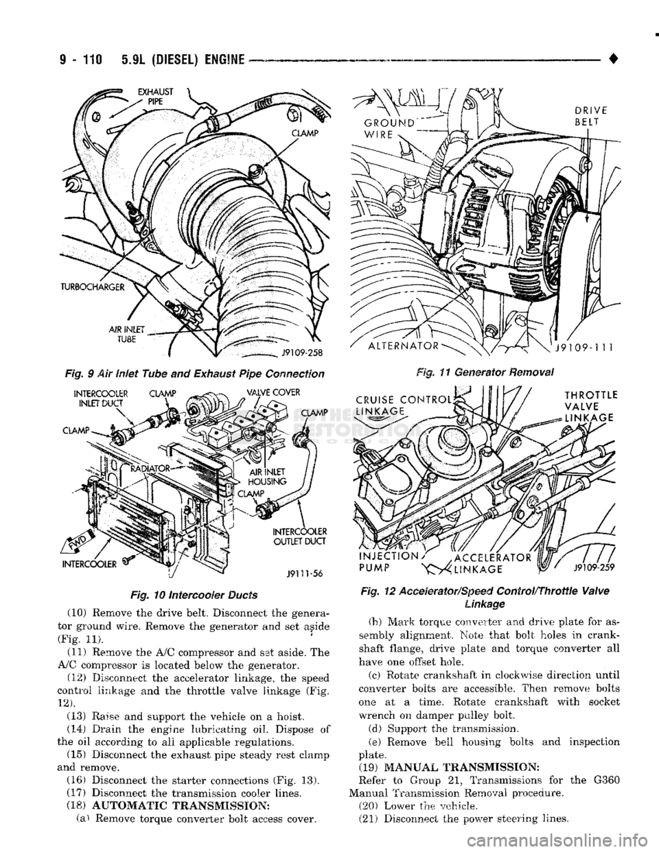
(10) Remove the drive belt. Disconnect the genera
tor ground wire. Remove the generator and set aside (Fig. 11).
(11) Remove the A/0 compressor and set aside. The
A/C compressor is located below the generator. (12) Disconnect the accelerator linkage, the speed
control linkage and the throttle valve linkage (Fig.
12).
(13) Raise and support the vehicle on a hoist.
(14)
Drain the engine lubricating oil. Dispose of
the oil according to all applicable regulations. (15) Disconnect the exhaust pipe steady rest clamp
and remove. (16) Disconnect the starter connections (Fig. 13).
(17) Disconnect the transmission cooler lines.
(18) AUTOMATIC TRANSMISSION: (a) Remove torque converter bolt access cover. •
Fig, 11 Generator Removal
Fig. 12 Accelerator/Speed
Control/Throttle
Valve
Linkage
(b) Mark
torque
converter and
drive
plate for
as
sembly
alignment.
Note
that bolt
holes
in crank
shaft flange, drive plate and torque converter all
have
one offset hole.
(c) Rotate crankshaft in clockwise direction until
converter
bolts
are accessible. Then remove
bolts
one
at a
time.
Rotate crankshaft with socket wrench on damper pulley bolt.
(d) Support the transmission.
(e)
Remove bell housing bolts and inspection
plate. (19) MANUAL TRANSMISSION:
Refer to Group 21, Transmissions for the G360
Manual Transmission Removal procedure. (20) Lower the vehicle.
(21) Disconnect the power steering lines.
Page 727 of 1502
9
- 122 5.9L
(DIESEL) ENGINE
•
GEAR
HOUSING
/
COVER
GEAR
HOUSING
REMOVAL
(1) Remove the engine assembly from the vehicle.
(2) Remove the front end components and the gear
housing cover (refer to Gear Housing Cover Removal
for the proper procedures). (3) Remove the following:
• Camshaft
• Gear driven accessories
• Fuel injection pump (refer to Group 14, Fuel Sys
tem)
• Fan hub assembly (refer to Group 7, Cooling Sys
tem)
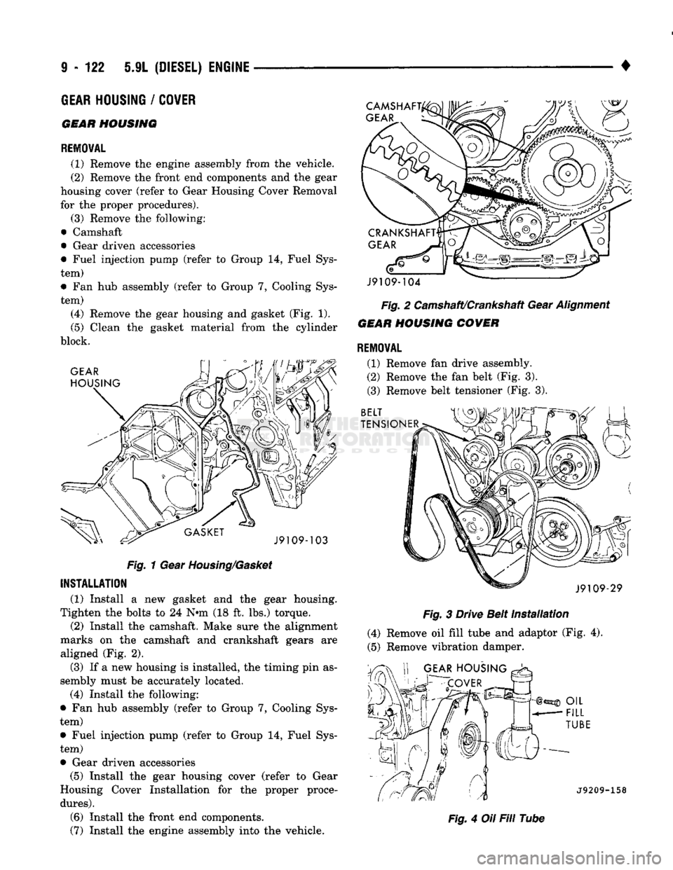
(4) Remove the gear housing and gasket (Fig. 1).
(5) Clean the gasket material from the cylinder
block.
Fig.
1 Gear
Housing/Gasket
INSTALLATION
(1) Install a new gasket and the gear housing.
Tighten the bolts to 24 N*m (18 ft. lbs.) torque. (2) Install the camshaft. Make sure the alignment
marks on the camshaft and crankshaft gears are aligned (Fig. 2),
(3) If a new housing is installed, the timing pin as
sembly must be accurately located. (4) Install the following:
• Fan hub assembly (refer to Group 7, Cooling Sys
tem)
• Fuel injection pump (refer to Group 14, Fuel Sys
tem) • Gear driven accessories (5) Install the gear housing cover (refer to Gear
Housing Cover Installation for the proper proce
dures).
(6) Install the front end components.
(7) Install the engine assembly into the vehicle. J9109-104
Fig.
2 Camshaft/Crankshaft Gear
Alignment
GEAR
HOUSING COVER REMOVAL
(1) Remove fan drive assembly.
(2) Remove the fan belt (Fig. 3).
(3) Remove belt tensioner (Fig. 3).
Fig.
3 Drive Belt
Installation
(4) Remove oil fill tube and adaptor (Fig. 4).
(5) Remove vibration damper.
-158
Fig.
4 Oil Fill Tube
Page 728 of 1502
•
5.9L
(DIESEL)
ENGINE
9 - 123 (6) Remove the bolts that hold the gear cover to
the gear housing. (7) Gently pry the cover away from the housing,
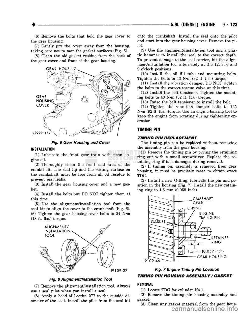
taking care not to mar the gasket surfaces (Fig. 5). (8) Clean the old gasket residue from the back of
the gear cover and front of the gear housing.
Fig.
5 Gear
Housing
and
Cover
INSTALLATION
(1) Lubricate the front gear train with clean en
gine oil.
(2) Thoroughly clean the front seal area of the
crankshaft. The seal lip and the sealing surface on
the crankshaft must be free from all oil residue to
prevent seal leaks.
(3) Install the gear housing cover and a new gas
ket.
(4) Install the bolts but DO NOT tighten them at
this time.
(5) Use the alignment/installation tool from the
seal kit to align the cover to the crankshaft (Fig. 6). (6) Tighten the gear housing cover bolts to 24 N*m
(18 ft. lbs.) torque.
Fig.
6 Alignment/Installation Tool
(7) Remove the alignment/installation tool. Always
use a seal pilot when you install a seal.
(8) Apply a bead of Loctite 277 to the outside di
ameter of the seal. Install the pilot from the seal kit onto the crankshaft. Install the seal onto the pilot
and start into the gear housing cover. Remove the pi
lot. (9) Use the alignment/installation tool and a plas
tic hammer to install the seal to the correct depth.
To prevent damage to the seal carrier, hit the align ment/installation tool alternately at the 12, 3, 6 and 9 o'clock positions.
(10) Install the oil fill tube and mounting bolts.
Tighten the bolts to 43 N*m (32 ft. lbs.) torque. (11) Install the vibration damper. DO NOT tighten
the bolts to the correct torque valve at this time.
(12) Install the belt tensioner. Tighten the mount
ing bolts to 43 Nnn (32 ft. lbs.) torque. (13) Raise the belt tensioner to install the belt.
(14) Tighten the vibration damper bolts to 125
N*m (92 ft. lbs.) torque. Use an engine barring tool to keep the engine from rotating during tightening op
eration.
TIMING
PIN TIMING PIN REPLACEMENT The timing pin can be replaced without removing
the assembly from the gear housing. (1) Remove the timing pin by prying the retaining
ring out with a small screwdriver. Replace the re
taining ring if it is damaged during removal.
(2) If timing pin assembly is removed from gear
housing, it must be precisely reset to obtain exact
TDC.
(3) Install a new O-Ring, lubricate the pin and po
sition in the housing (Fig. 7). Install the new retain
ing ring to 1.5 mm (0.059 inch).
Fig.
7
Engine
Timing Pin Location
TIMING PIN HOUSING ASSEMBLY/ GASKET
REMOVAL
(1) Locate TDC for cylinder No.l.
(2) Remove the timing pin housing assembly and
gasket.
(3) Clean any gasket material from the gear hous-
Page 732 of 1502
•
5.9L
(DIESEL) ENGINE
9 - 127
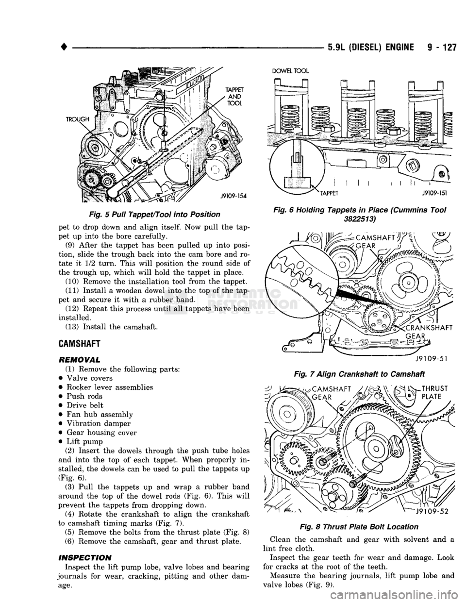
Fig.
5 Pull
Tappet/Tool
into
Position pet to drop down and align
itself.
Now pull the tap
pet up into the bore carefully. (9) After the tappet has been pulled up into posi
tion, slide the trough back into the cam bore and ro tate it 1/2 turn. This will position the round side of
the trough up, which will hold the tappet in place.
(10) Remove the installation tool from the tappet. (11) Install a wooden dowel into the top of the tap
pet and secure it with a rubber band.
(12) Repeat this process until all tappets have been
installed. (13) Install the camshaft.
CAMSHAFT
REMOVAL (1) Remove the following parts:
• Valve covers
• Rocker lever assemblies
• Push rods • Drive belt
• Fan hub assembly • Vibration damper
• Gear housing cover
• Lift pump (2) Insert the dowels through the push tube holes
and into the top of each tappet. When properly in
stalled, the dowels can be used to pull the tappets up (Fig. 6).
(3) Pull the tappets up and wrap a rubber band
around the top of the dowel rods (Fig. 6). This will
prevent the tappets from dropping down.
(4) Rotate the crankshaft to align the crankshaft
to camshaft timing marks (Fig. 7).
(5) Remove the bolts from the thrust plate (Fig. 8)
(6) Remove the camshaft, gear and thrust plate.
INSPECTION
Inspect the lift pump lobe, valve lobes and bearing
journals for wear, cracking, pitting and other dam
age.
DOWEL
TOOL
Fig.
6
Holding
Tappets in Place
(Cummins
Tool 3822513)
J9109-51
Fig.
7
Align
Crankshaft to Camshaft
Fig.
8 Thrust
Plate
Bolt
Location
Clean the camshaft and gear with solvent and a
lint free cloth.
Inspect the gear teeth for wear and damage. Look
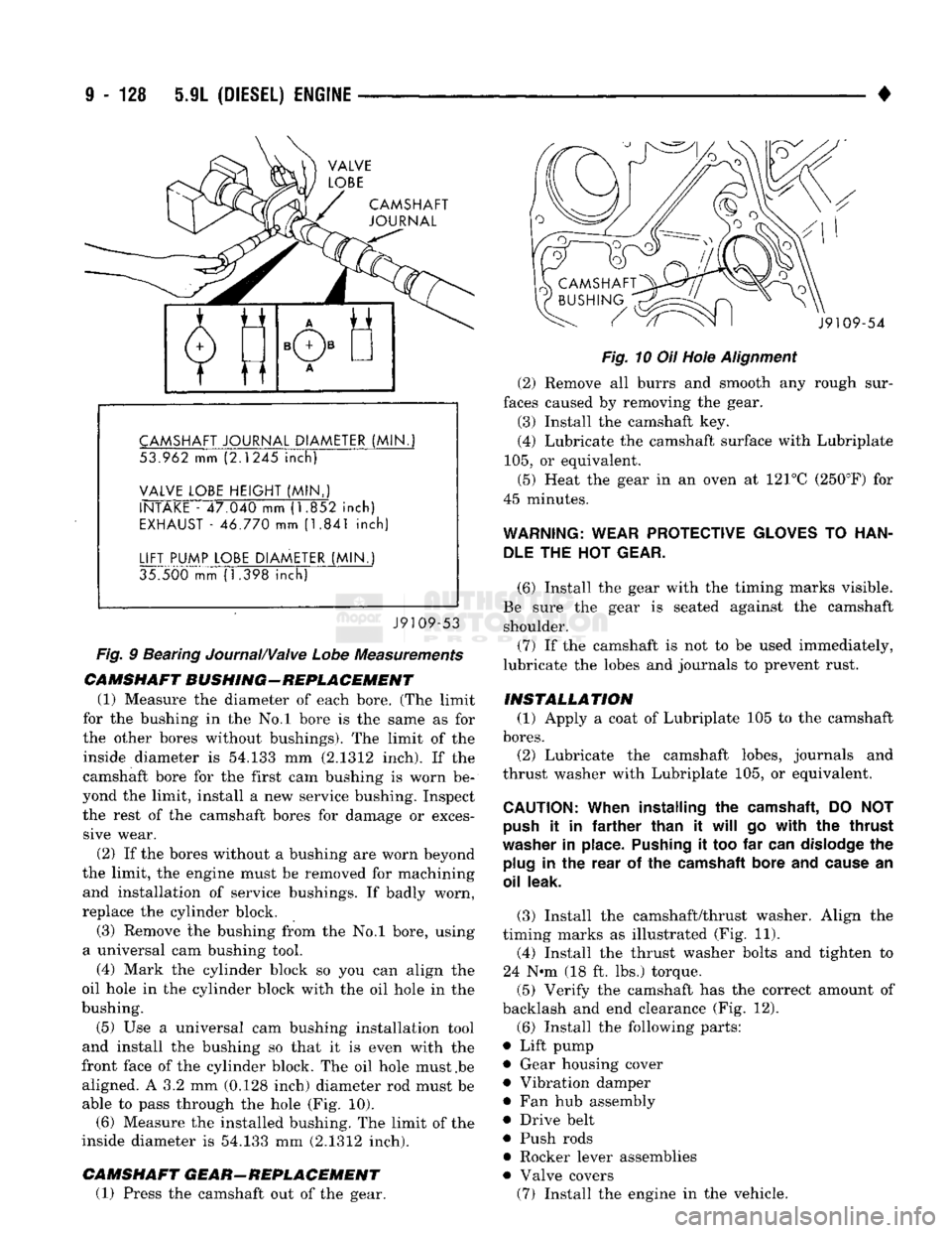
for cracks at the root of the teeth. Measure the bearing journals, lift pump lobe and
valve lobes (Fig. 9).
Page 733 of 1502
9
- 128 5.9L
(DIESEL)
ENGINE
•
CAMSHAFT
JOURNAL
CAMSHAFT
JOURNAL
DIAMETER
(MIN.
53.962 mm (2.1245
inch)
VALVE
LOBE
HEIGHT
(MIN..)
INTAKE
- 47.040 mm (1.852
inch)
EXHAUST
- 46.770 mm (1.841
inch)
LIFT
PUMP
LOBE
DIAMETER
(MIN.)
35.500 mm (1.398
inch)
J9109-53
Fig.
9 Bearing Journal/Valve
Lobe
Measurements
CAMSHAFT
BUSHING-REPLACEMENT
(1) Measure the diameter of each bore. (The limit
for the bushing in the No.l bore is the same as for
the other bores without bushings). The limit of the inside diameter is 54.133 mm (2.1312 inch). If the
camshaft bore for the first cam bushing is worn be
yond the limit, install a new service bushing. Inspect the rest of the camshaft bores for damage or exces sive wear.
(2) If the bores without a bushing are worn beyond
the limit, the engine must be removed for machining and installation of service bushings. If badly worn,
replace the cylinder block.
(3) Remove the bushing from the No.l bore, using
a universal cam bushing tool.
(4) Mark the cylinder block so you can align the
oil hole in the cylinder block with the oil hole in the
bushing.
(5) Use a universal cam bushing installation tool
and install the bushing so that it is even with the
front face of the cylinder block. The oil hole must .be aligned. A 3.2 mm (0.128 inch) diameter rod must be able to pass through the hole (Fig. 10). (6) Measure the installed bushing. The limit of the
inside diameter is 54.133 mm (2.1312 inch).
CAMSHAFT
GEAR-REPLACEMENT
(1) Press the camshaft out of the gear. J9109-54
Fig.
10 Oil Hole
Alignment
(2) Remove all burrs and smooth any rough sur
faces caused by removing the gear. (3) Install the camshaft key.
(4) Lubricate the camshaft surface with Lubriplate
105,
or equivalent.
(5) Heat the gear in an oven at 121°C (250°F) for
45 minutes.
WARNING:
WEAR
PROTECTIVE
GLOVES
TO
HAN
DLE
THE HOT
GEAR.
(6) Install the gear with the timing marks visible.
Be sure the gear is seated against the camshaft shoulder.
(7) If the camshaft is not to be used immediately,
lubricate the lobes and journals to prevent rust.
INSTALLATION
(1) Apply a coat of Lubriplate 105 to the camshaft
bores.
(2) Lubricate the camshaft lobes, journals and
thrust washer with Lubriplate 105, or equivalent.
CAUTION:
When
installing
the
camshaft,
DO NOT
push
it in
farther
than
it
will
go
with
the
thrust
washer
in
place.
Pushing
it too far
can
dislodge
the
plug
in the
rear
of the
camshaft
bore
and
cause
an
oil
leak.
(3) Install the camshaft/thrust washer. Align the
timing marks as illustrated (Fig. 11). (4) Install the thrust washer bolts and tighten to
24 N-m (18 ft. lbs.) torque.
(5) Verify the camshaft has the correct amount of
backlash and end clearance (Fig. 12).
(6) Install the following parts:
• Lift pump • Gear housing cover
• Vibration damper
• Fan hub assembly
• Drive belt
• Push rods
• Rocker lever assemblies
• Valve covers (7) Install the engine in the vehicle.
Page 745 of 1502
9
- 140 5.9L
(DIESEL)
ENGINE
• procedure providing
the
thrust surface width
is not
being ground.
The
preferred procedure must
be
used
when
the
main bearing thrust width surface
is
ground. When
the
thrust surface width requires
grinding,
the
main journal must
be
ground
to the
same undersize dimension
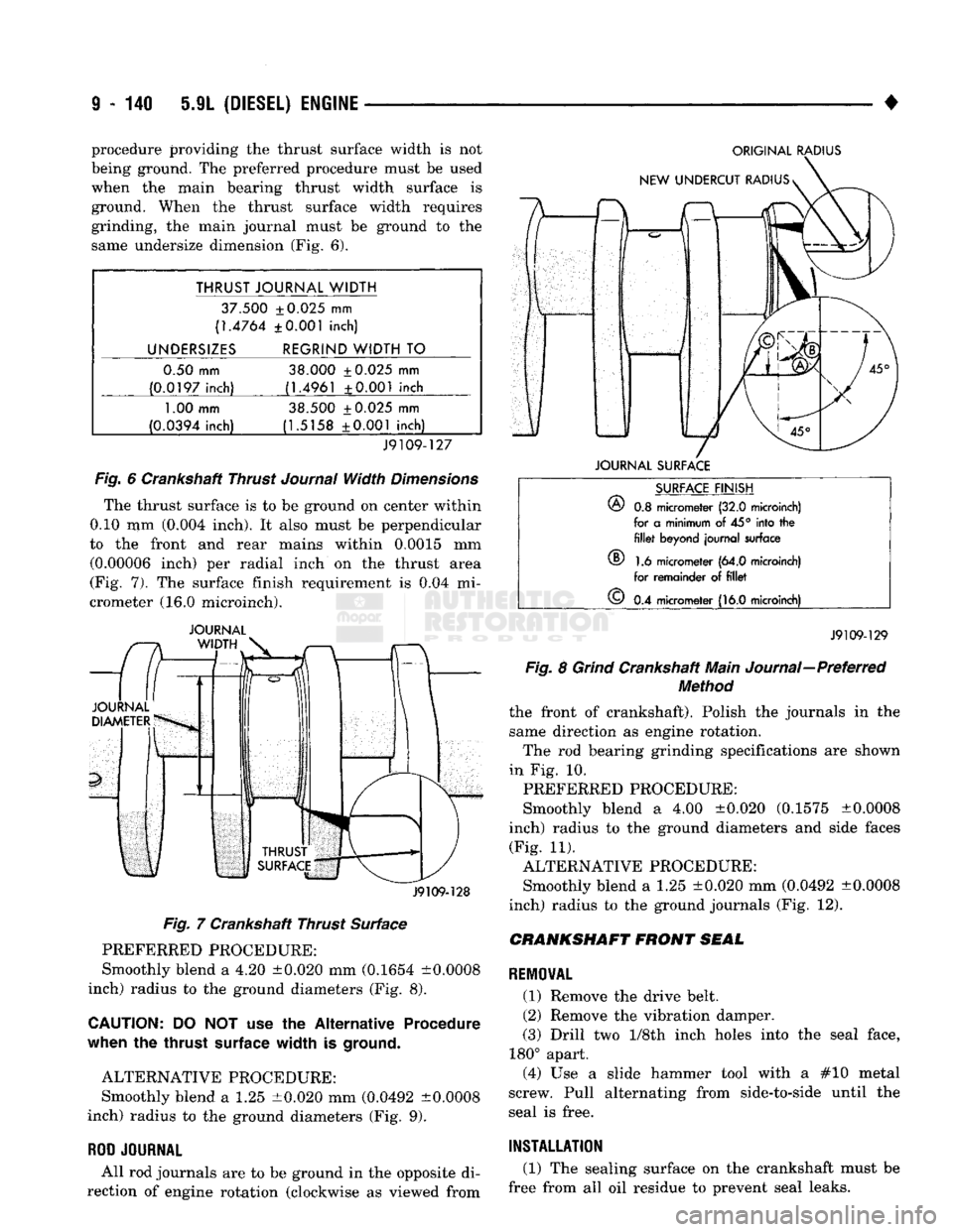
(Fig. 6).
THRUST JOURNAL WIDTH
37.500 ±0.025
mm
(1.4764 ±0.001 inch)
UNDERSIZES REGRIND WIDTH
TO
0.50 mm 38.000 ±0.025
mm
(0.0197 inch) (1.4961 ±0.001 inch
1.00
mm 38.500 ±0.025
mm
(0.0394 inch) (1.5158 ±0.001 inch)
J9109-127
Fig.
6
Crankshaft Thrust
Journal
Width
Dimensions
The thrust surface
is to be
ground
on
center within
0.10
mm
(0.004 inch).
It
also must
be
perpendicular
to
the
front
and
rear mains within 0.0015
mm
(0.00006 inch)
per
radial inch
on the
thrust area
(Fig.
7). The
surface finish requirement
is 0.04 mi
crometer
(16.0
microinch).
JOURNAL
J9109-128
Fig.
7
Crankshaft Thrust Surface PREFERRED PROCEDURE:
Smoothly blend
a 4.20
±0.020
mm
(0.1654 ±0.0008
inch) radius
to the
ground diameters
(Fig. 8).
CAUTION:
DO NOT use the
Alternative Procedure
when
the
thrust
surface
width
is
ground.
ALTERNATIVE PROCEDURE: Smoothly blend
a 1.25
±0.020
mm
(0.0492 ±0.0008
inch) radius
to the
ground diameters
(Fig. 9).
ROD
JOURNAL
All
rod
journals
are to be
ground
in the
opposite
di
rection
of
engine rotation (clockwise
as
viewed from
ORIGINAL
RADIUS
JOURNAL
SURFACE
®
SURFACE
FINISH
®
0.8
micrometer
(32.0
microinch)
for
a
minimum
of 45°
into
the fillet
beyond journal surface
1.6
micrometer
(64.0
microinch)
for remainder
of fillet
©
0.4
micrometer
(16.0
microinch)
J9109-129
Fig.
8
Grind
Crankshaft Main Journal—Preferred
Method
the front
of
crankshaft). Polish
the
journals
in the
same direction
as
engine rotation. The
rod
bearing grinding specifications
are
shown
in
Fig. 10.
PREFERRED PROCEDURE:
Smoothly blend
a 4.00
±0.020 (0.1575 ±0.0008
inch) radius
to the
ground diameters
and
side faces (Fig.
11).
ALTERNATIVE PROCEDURE: Smoothly blend
a 1.25
±0.020
mm
(0.0492 ±0.0008
inch) radius
to the
ground journals
(Fig. 12).
CRANKSHAFT
FRONT
SEAL
REMOVAL
(1) Remove
the
drive belt.
(2) Remove
the
vibration damper.
(3) Drill
two 1/Sth
inch holes into
the
seal face,
180° apart. (4)
Use a
slide hammer tool with
a #10
metal
screw. Pull alternating from side-to-side until
the
seal
is
free.
INSTALLATION
(1)
The
sealing surface
on the
crankshaft must
be
free from
all oil
residue
to
prevent seal leaks.
Page 746 of 1502
5-9L
(DIESEL) ENGINE
9 - 141
ORIGINAL RADIUS
NEW UNDERCUT RADIUS JOURNAL SURFACE ORIGINAL RADIUS
NEW UNDERCUT RADIUSs
SURFACE FINISH
®
0.8 micrometer (32.0 microinch) for a minimum of
45°
into the
fillet
beyond journal surface
(D 1.6 micrometer (64.0 microinch) for remainder of
fillet
©
0.4 micrometer (16.0 microinch)
WIDTH
OF
REGRIND/UNDERCUT RADIUS
®
34.5
±0.025
mm
(1.358
±0.001
in)
JOURNAL SURFACE
J9109-130
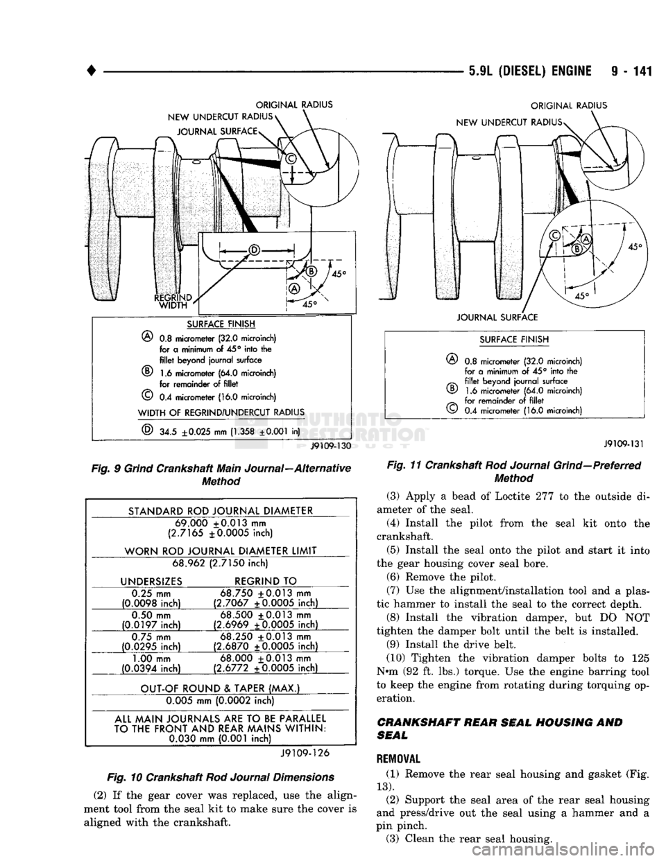
Fig. 9 Grind Crankshaft Main Journal—Alternative Method
STANDARD ROD JOURNAL DIAMETER 69.000 +0.013 mm
(2.7165 ±0.0005 inch)
WORN ROD JOURNAL DIAMETER LIMIT 68.962 (2.7150 inch)
UNDERSIZES REGRIND TO
0.25 mm
(0.0098 inch) 68.750 +0.013 mm
(2.7067 ±0.0005 inch)
0.50 mm
(0.0197 inch) 68.500 +0.013 mm
(2.6969 ±0.0005 inch)
0.75 mm
(0.0295 inch) 68.250 +0.013 mm
(2.6870 ±0.0005 inch)
1.00 mm
(0.0394 inch) 68.000 +0.013 mm
(2.6772 ±0.0005 inch)
OUT-OF ROUND & TAPER (MAX.) 0.005 mm (0.0002 inch)
ALL MAIN JOURNALS
ARE
TO
BE
PARALLEL
TO THE FRONT AND REAR MAINS WITHIN: 0.030 mm (0.001 inch)
J9109-126
Fig. 10 Crankshaft Rod Journal Dimensions
(2) If the gear cover was replaced, use the align
ment tool from the seal kit to make sure the cover is aligned with the crankshaft.
SURFACE FINISH
©
0.8 micrometer (32.0 microinch)
for a minimum of 45° into the
fillet
beyond journal surface 1.6 micrometer (64.0 microinch)
for remainder of
fillet
0.4 micrometer (16.0 microinch)
CD
©
J9109-131
Fig. 11 Crankshaft Rod Journal Grind—Preferred Method
(3) Apply a bead of Loctite 277 to the outside di
ameter of the seal.
(4) Install the pilot from the seal kit onto the
crankshaft.
(5) Install the seal onto the pilot and start it into
the gear housing cover seal bore. (6) Remove the pilot.
(7) Use the alignment/installation tool and a plas
tic hammer to install the seal to the correct depth.
(8) Install the vibration damper, but DO NOT
tighten the damper bolt until the belt is installed.
(9) Install the drive belt.
(10) Tighten the vibration damper bolts to 125
Nun (92 ft. lbs.) torque. Use the engine barring tool
to keep the engine from rotating during torquing op eration.
CRANKSHAFT REAR SEAL HOUSING AND
SEAL
REMOVAL
(1) Remove the rear seal housing and gasket (Fig.
13).
(2) Support the seal area of the rear seal housing
and press/drive out the seal using a hammer and a
pin pinch.
(3) Clean the rear seal housing.
Page 749 of 1502
9 - 146 5.9L (DIESEL) ENGINE
•
DIAL
INDICATOR
CYLINDER BLOCK
GASKET
J9109-97
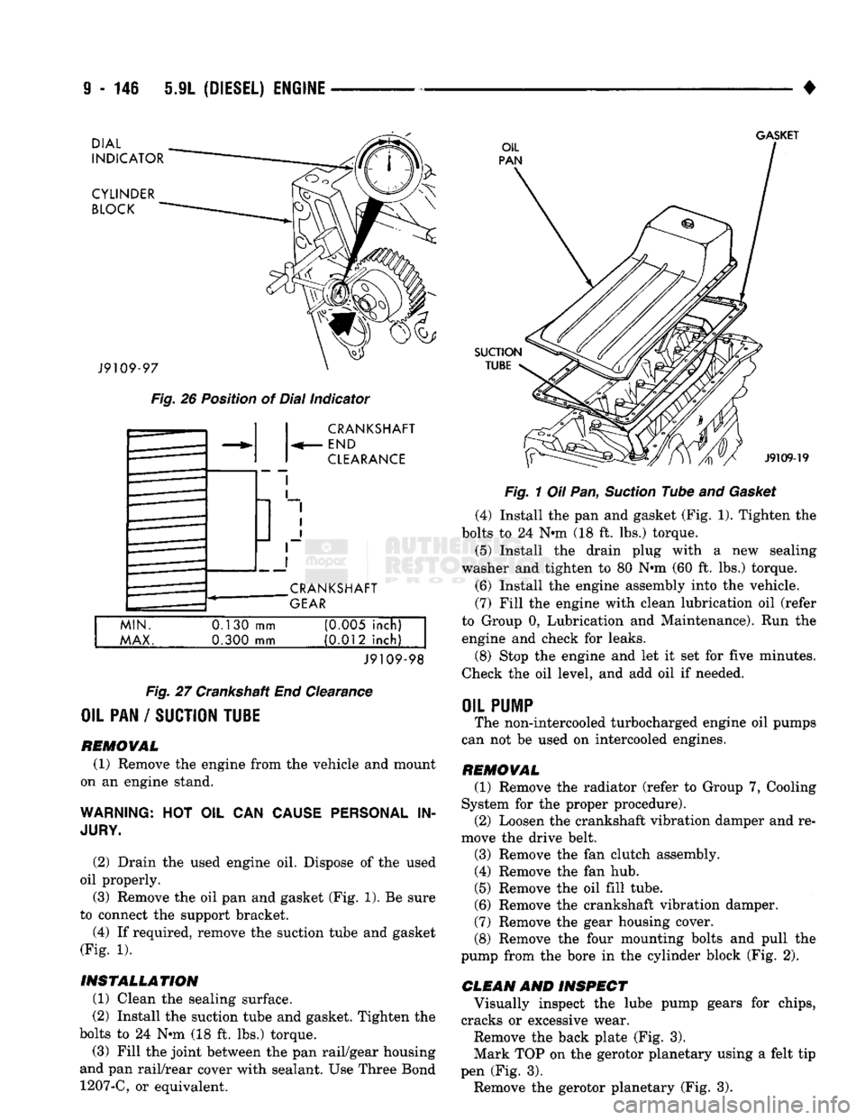
Fig.
26 Position of Dial Indicator CRANKSHAFT
END
CLEARANCE
CRANKSHAFT
GEAR
MIN.
MAX.
0.130
mm
0.300 mm (0M5 inch)
(0.012 inch)
J9109-98
Fig.
27 Crankshaft End Clearance
OIL PAN / SUCTION TU1E
REMOVAL (1) Remove the engine from the vehicle and mount
on an engine stand.
WARNING:
HOT OIL CAN
CAUSE PERSONAL
IN
JURY.
(2) Drain the used engine oil. Dispose of the used
oil properly. (3) Remove the oil pan and gasket (Fig. 1). Be sure
to connect the support bracket.
(4) If required, remove the suction tube and gasket
(Fig. 1).
INSTALLATION (1) Clean the sealing surface.
(2) Install the suction tube and gasket. Tighten the
bolts to 24 Nin (18 ft. lbs.) torque.
(3) Fill the joint between the pan rail/gear housing
and pan rail/rear cover with sealant. Use Three Bond 1207-C, or equivalent.
SUCTION
TUBE
J9109-19
Fig.
1 Oil Pan,
Suction
Tube and
Gasket
(4) Install the pan and gasket (Fig. 1). Tighten the
bolts to 24 N-m (18 ft. lbs.) torque.
(5) Install the drain plug with
a
new sealing
washer and tighten to 80 Nnn (60 ft. lbs.) torque.
(6) Install the engine assembly into the vehicle.
(7) Fill the engine with clean lubrication oil (refer
to Group 0, Lubrication and Maintenance). Run the engine and check for leaks.
(8) Stop the engine and let it set for five minutes.
Check the oil level, and add oil if needed.
OIL
PUMP
The non-intercooled turbocharged engine oil pumps
can not be used on intercooled engines.
REMOVAL (1) Remove the radiator (refer to Group 7, Cooling
System for the proper procedure). (2) Loosen the crankshaft vibration damper and re
move the drive belt.
(3) Remove the fan clutch assembly. (4) Remove the fan hub.
(5) Remove the oil fill tube.
(6) Remove the crankshaft vibration damper.
(7) Remove the gear housing cover.
(8) Remove the four mounting bolts and pull the
pump from the bore in the cylinder block (Fig. 2).
CLEAN AND INSPECT Visually inspect the lube pump gears for chips,
cracks or excessive wear.
Remove the back plate (Fig. 3).
Mark TOP on the gerotor planetary using a felt tip
pen (Fig. 3). Remove the gerotor planetary (Fig. 3).
Page 756 of 1502
5.9L
(DIESEL)
ENGINE
9-153
TORQUE
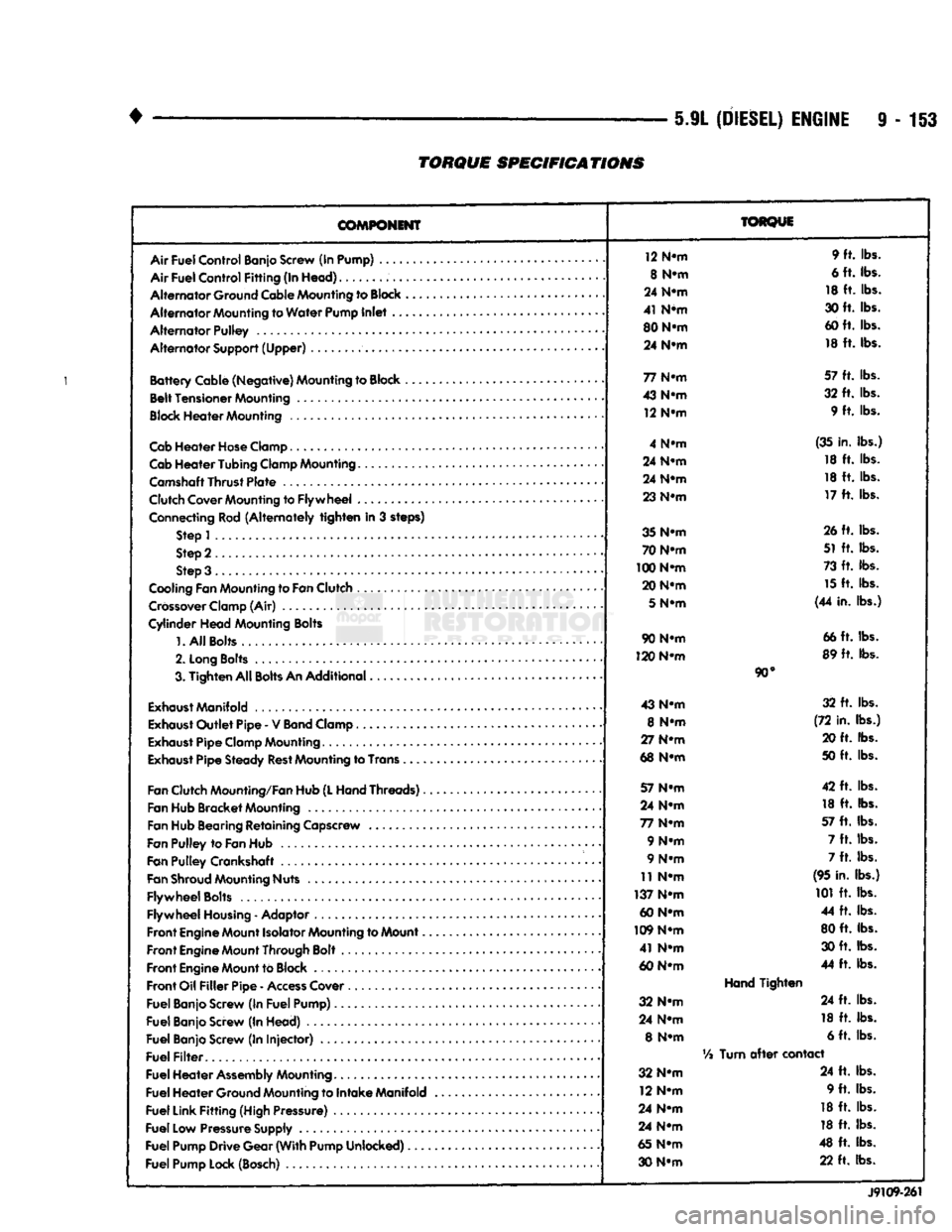
SPECIFICATIONS
COMPONENT
Air
Fuel
Control
Banjo Screw (In Pump) ....
Air
Fuel
Control
Fitting
(In
Head)
Alternator
Ground Cable Mounting to
Block
Alternator
Mounting to
Water
Pump
Inlet
..
Alternator
Pulley
Alternator
Support
(Upper)
Battery
Cable
(Negative)
Mounting to Block ,
Belt
Tensioner
Mounting
Block
Heater
Mounting
Cab
Heater
Hose
Clamp
Cab
Heater
Tubing
Clamp Mounting.......
Camshaft
Thrust
Plate
Clutch Cover Mounting to
Flywheel
...
Connecting Rod
(Alternately
tighten
in 3 steps) Step 1
Step 2
Step 3 .
Cooling Fan Mounting to
Fan
Clutch
Crossover
Clamp (Air)
Cylinder
Head
Mounting Bolts
1.
All
Bolts....
2.
Long
Bolts
.........
3.
Tighten
All
Bolts
An
Additional
Exhaust
Manifold
Exhaust
Outlet
Pipe
- V
Band
Clamp
Exhaust
Pipe
Clamp Mounting
Exhaust
Pipe
Steady
Rest
Mounting to Trans .
Fan
Clutch Mounting/Fan Hub
(L
Hand
Threads)..
Fan Hub
Bracket
Mounting
Fan Hub Bearing
Retaining
Capscrew
Fan
Pulley
to
Fan
Hub
Fan
Pulley
Crankshaft .
Fan
Shroud
Mounting Nuts
Flywheel
Bolts
Flywheel
Housing
- Adaptor
Front
Engine
Mount Isolator Mounting to Mount..
Front
Engine
Mount Through Bolt
Front
Engine
Mount to Block
Front
Oil
Filler
Pipe
-
Access
Cover
Fuel
Banjo Screw (In
Fuel
Pump)
Fuel
Banjo Screw (In
Head)
Fuel
Banjo Screw (In
Injector)
Fuel
Filter
Fuel
Heater
Assembly
Mounting
Fuel
Heater
Ground Mounting to
Intake
Manifold
Fuel
Link
Fitting
(High Pressure)
Fuel
Low Pressure Supply
Fuel
Pump
Drive
Gear
(With
Pump
Unlocked)
Fuel
Pump Lock (Bosch)
TORQUE
12 N-m 9 ft. lbs.
8 N-m 6 ft. lbs.
24 N-m 18 ft. lbs.
41 N*m 30 ft. lbs.
80 N-m 60 ft. lbs.
24 N-m 18 ft. lbs.
77 N-m 57 ft. lbs.
43 N-m 32 ft. lbs.
12 N-m 9 ft. lbs.
4 N-m (35 in. lbs.)
24 N-m 18 ft. lbs.
24 N-m 18 ft. lbs.
23 N-m 17 ft. lbs.
35 N-m 26 ft. lbs.
70 N-m 51 ft. lbs.
100 N-m 73 ft. lbs.
20 N-m 15 ft. lbs.
5
N-m (44 in. lbs.)
90 N-m 66 ft. lbs.
120 N-m 89 ft. lbs.
90°
43 N-m 32 ft. lbs.
8 N-m (72 in. lbs.)
27 N-m 20 ft. lbs.
68 N-m 50 ft. lbs.
57 N-m 42 ft. lbs.
24 N-m 18 ft. lbs.
77 N-m 57 ft. lbs.
9 N-m 7 ft. lbs.
9 N-m 7 ft. lbs.
11 N-m (95 in. lbs.)
137 N-m 101 ft. lbs.
60 N-m 44 ft. lbs.
109 N-m 80 ft. lbs.
41 N-m 30 ft. lbs.
60 N-m 44 ft. lbs.
Hand
Tighten
32 N-m 24 ft. lbs.
24 N-m 18 ft. lbs.
8 N-m 6 ft. lbs.
Vi
Turn
after
contact
32 N-m 24 ft. lbs.
12 N-m 9 ft. lbs.
24 N-m 18 ft. lbs.
24 N-m 18 ft. lbs.
65 N-m 48 ft. lbs.
30 N-m 22 ft. lbs.
J9109-261