brake sensor DODGE TRUCK 1993 Service User Guide
[x] Cancel search | Manufacturer: DODGE, Model Year: 1993, Model line: TRUCK, Model: DODGE TRUCK 1993Pages: 1502, PDF Size: 80.97 MB
Page 247 of 1502
5
- 60
BRAKES
Fig.
2
Antilock
Electronic Control
Module
RWAL
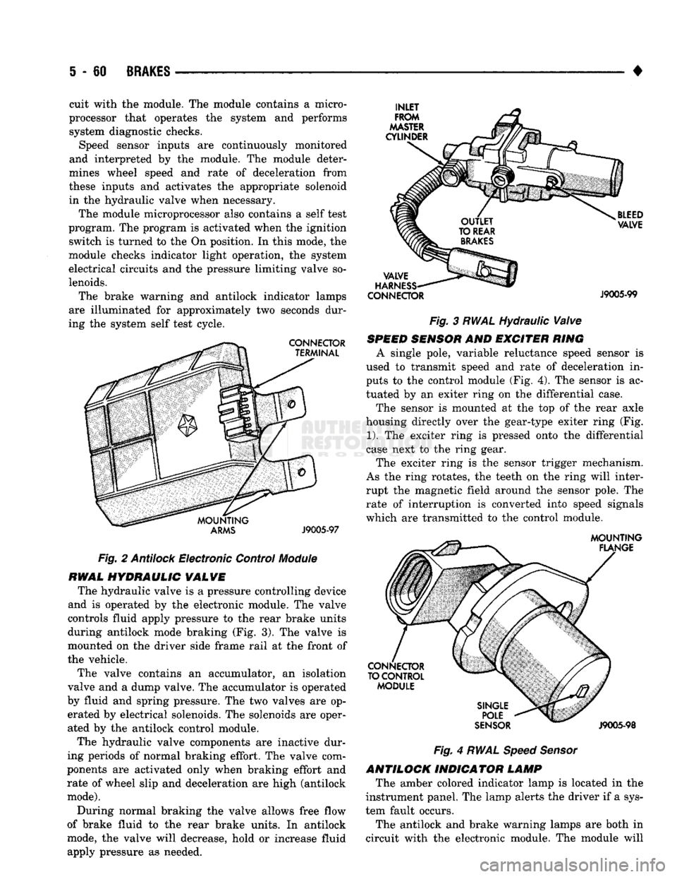
HYDRAULIC
VALVE
The hydraulic valve is a pressure controlling device
and is operated by the electronic module. The valve
controls fluid apply pressure to the rear brake units
during antilock mode braking (Fig. 3). The valve is
mounted on the driver side frame rail at the front of
the vehicle.
The valve contains an accumulator, an isolation
valve and a dump valve. The accumulator is operated
by fluid and spring pressure. The two valves are op erated by electrical solenoids. The solenoids are oper
ated by the antilock control module.
The hydraulic valve components are inactive dur
ing periods of normal braking effort. The valve com
ponents are activated only when braking effort and rate of wheel slip and deceleration are high (antilock
mode).
During normal braking the valve allows free flow
of brake fluid to the rear brake units. In antilock
mode, the valve will decrease, hold or increase fluid
apply pressure as needed. •
CONNECTOR
J9005-99
Fig. 3 RWAL Hydraulic Valve
SPEED
SENSOR
AND EXCITER RING
A single pole, variable reluctance speed sensor is
used to transmit speed and rate of deceleration in
puts to the control module (Fig. 4). The sensor is ac
tuated by an exiter ring on the differential case.
The sensor is mounted at the top of the rear axle
housing directly over the gear-type exiter ring (Fig.
1).
The exciter ring is pressed onto the differential
case next to the ring gear.
The exciter ring is the sensor trigger mechanism.
As the ring rotates, the teeth on the ring will inter
rupt the magnetic field around the sensor pole. The rate of interruption is converted into speed signals
which are transmitted to the control module.
Fig.
4
RWAL Speed Sensor
ANTILOCK INDICATOR LAMP The amber colored indicator lamp is located in the
instrument panel. The lamp alerts the driver if a sys
tem fault occurs.
The antilock and brake warning lamps are both in
circuit with the electronic module. The module will
cuit with the module. The module contains a micro
processor that operates the system and performs system diagnostic checks. Speed sensor inputs are continuously monitored
and interpreted by the module. The module deter
mines wheel speed and rate of deceleration from
these inputs and activates the appropriate solenoid in the hydraulic valve when necessary.
The module microprocessor also contains a self test
program. The program is activated when the ignition switch is turned to the On position. In this mode, the
module checks indicator light operation, the system
electrical circuits and the pressure limiting valve so
lenoids.
The brake warning and antilock indicator lamps
are illuminated for approximately two seconds dur
ing the system self test cycle.
Page 248 of 1502
•
BRAKES
5 - 61 cause the two lamps to illuminate or flash to alert
the driver that system operation is either normal or
that a fault has occurred.
SYSTEM
OPERATION
During light brake applications, rear wheel decel
eration and/or slip is not sufficient to activate the an
tilock system. Brake fluid apply pressure at the rear
wheels is normal. However, when braking effort, de gree of wheel slip and rate of deceleration approach
programmed limits, sensor inputs will cause the module to activate the system.
Normal
Braking
Mode
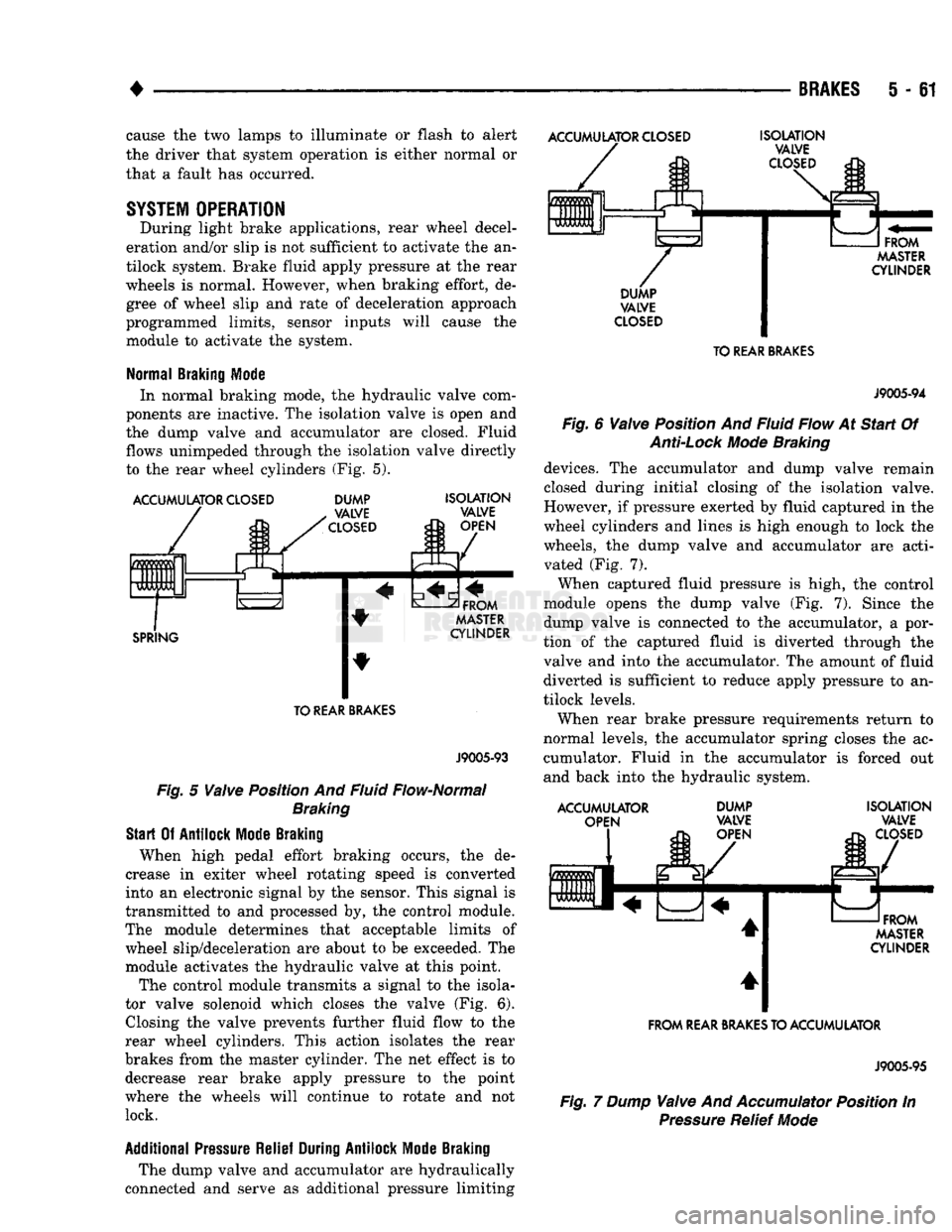
In normal braking mode, the hydraulic valve com
ponents are inactive. The isolation valve is open and
the dump valve and accumulator are closed. Fluid
flows unimpeded through the isolation valve directly
to the rear wheel cylinders (Fig. 5).
ACCUMULATOR
CLOSED
ACCUMULATOR
CLOSED
0 m
m
0 UUb Ft
L DUMP
VALVE
CLOSED
SPRING
ISOLATION
VALVE
OPEN
FROM
MASTER
CYLINDER TO
REAR
BRAKES
J9005-93
Fig.
5
Valve
Position And Fluid Flow-Normal
Braking
Start
Of
Antilock
Mode
Braking
When high pedal effort braking occurs, the de
crease in exiter wheel rotating speed is converted
into an electronic signal by the sensor. This signal is
transmitted to and processed by, the control module.
The module determines that acceptable limits of wheel slip/deceleration are about to be exceeded. The
module activates the hydraulic valve at this point.
The control module transmits a signal to the isola
tor valve solenoid which closes the valve (Fig. 6). Closing the valve prevents further fluid flow to the
rear wheel cylinders. This action isolates the rear
brakes from the master cylinder. The net effect is to decrease rear brake apply pressure to the point
where the wheels will continue to rotate and not lock.
Additional
Pressure
Relief
During
Antilock
Mode
Braking
The dump valve and accumulator are hydraulically
connected and serve as additional pressure limiting
ISOLATION
VALVE
CLOSED
FROM
MASTER
CYLINDER
DUMP
VALVE
CLOSED
TO
REAR
BRAKES
J9005-94
Fig.
6
Valve
Position And Fluid Flow At
Start
Of
Anti-Lock
Mode
Braking
devices. The accumulator and dump valve remain
closed during initial closing of the isolation valve.
However, if pressure exerted by fluid captured in the
wheel cylinders and lines is high enough to lock the
wheels, the dump valve and accumulator are acti vated (Fig. 7).
When captured fluid pressure is high, the control
module opens the dump valve (Fig. 7). Since the
dump valve is connected to the accumulator, a por
tion of the captured fluid is diverted through the
valve and into the accumulator. The amount of fluid diverted is sufficient to reduce apply pressure to an
tilock levels.
When rear brake pressure requirements return to
normal levels, the accumulator spring closes the ac cumulator. Fluid in the accumulator is forced out
and back into the hydraulic system.
ACCUMULATOR OPEN DUMP
VALVE
OPEN ISOLATION
VALVE
CLOSED
FROM
MASTER
CYLINDER
FROM
REAR
BRAKES
TO ACCUMULATOR
J9005-95
Fig.
7 Dump
Valve
And
Accumulator
Position In
Pressure
Relief
Mode
Page 249 of 1502
i - 62
BRAKES
•
Isolation/Dump
Valve Cycle Times
Activation (opening/closing) of the isolation and
dump valves is continuous during antilock operation.
The valves cycle rapidly in response to speed sensor inputs and control module signal commands. Cycle
times are measured in milliseconds.
As the demand for antilock mode brake operation
is decreased, the module deactivates the hydraulic
valve components to restore normal brake operation.
ANTILOCK
SERVICE
DIAGNOSIS
GENERAL INFORMATION An antilock system malfunction will be indicated
by illumination of the amber antilock warning lamp.
The red brake warning lamp may also illuminate.
If a problem occurs, system diagnosis should begin
with a fluid level check followed by a visual exami
nation of the system electrical and hydraulic connec
tions.
If obvious defects (low fluid, leaks, loose connections, etc.) are not evident, road test the vehi
cle.
A road test should help determine if a malfunc
tion is actually related to an antilock component.
During the road test, note if other conditions are
evident such as a low pedal, pull, grab, or similar condition. Remember that brake malfunctions such as low fluid, system leaks, parking brakes partially
applied, will also affect the antilock system. The idea
is to determine if a malfunction is actually related to
an anti-lock component.
If a road test does reveal a problem, repeat the
road test with the owner driving. Make sure the owner is not riding the brake pedal, or has forgotten
to release the parking brakes. Either situation will
generate a fault and cause the antilock light to illu
minate.
SYSTEM FAULT
CODES
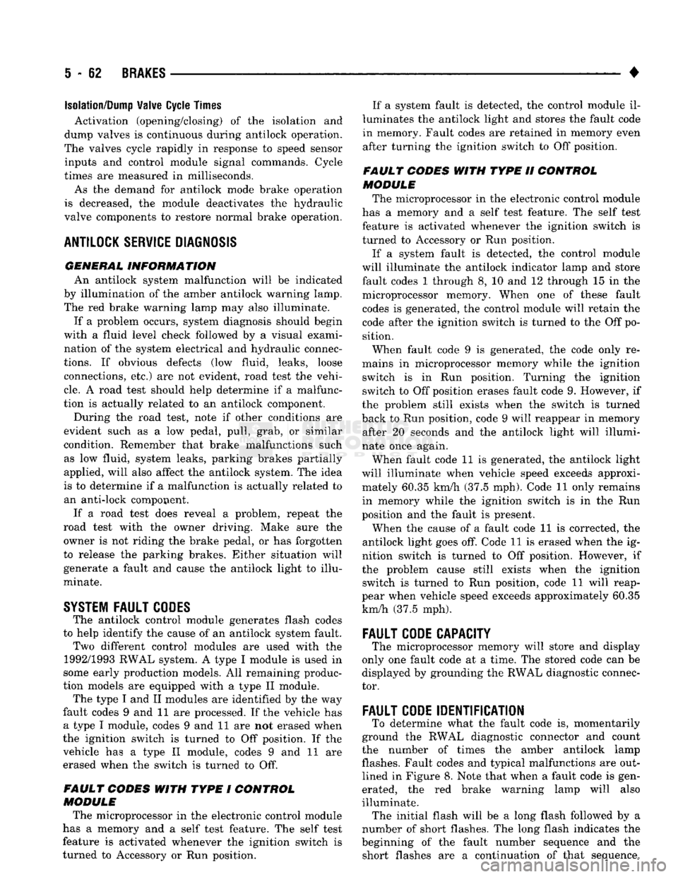
The antilock control module generates flash codes
to help identify the cause of an antilock system fault. Two different control modules are used with the
1992/1993 RWAL system. A type I module is used in
some early production models. All remaining produc
tion models are equipped with a type II module. The type I and II modules are identified by the way
fault codes 9 and 11 are processed. If the vehicle has a type I module, codes 9 and 11 are not erased when
the ignition switch is turned to Off position. If the vehicle has a type II module, codes 9 and 11 are
erased when the switch is turned to Off.
FAULT CODES WITH TYPE I CONTROL
MODULE
The microprocessor in the electronic control module
has a memory and a self test feature. The self test
feature is activated whenever the ignition switch is
turned to Accessory or Run position. If a system fault is detected, the control module il
luminates the antilock light and stores the fault code
in memory. Fault codes are retained in memory even after turning the ignition switch to Off position.
FAULT CODES WITH TYPE II CONTROL
MODULE The microprocessor in the electronic control module
has a memory and a self test feature. The self test
feature is activated whenever the ignition switch is
turned to Accessory or Run position.
If a system fault is detected, the control module
will illuminate the antilock indicator lamp and store
fault codes 1 through 8, 10 and 12 through 15 in the
microprocessor memory. When one of these fault
codes is generated, the control module will retain the code after the ignition switch is turned to the Off po
sition.
When fault code 9 is generated, the code only re
mains in microprocessor memory while the ignition switch is in Run position. Turning the ignition
switch to Off position erases fault code 9. However, if
the problem still exists when the switch is turned
back to Run position, code 9 will reappear in memory after 20 seconds and the antilock light will illumi
nate once again.
When fault code 11 is generated, the antilock light
will illuminate when vehicle speed exceeds approxi mately 60.35 km/h (37.5 mph). Code 11 only remains in memory while the ignition switch is in the Run
position and the fault is present.
When the cause of a fault code 11 is corrected, the
antilock light goes off. Code 11 is erased when the ig
nition switch is turned to Off position. However, if
the problem cause still exists when the ignition switch is turned to Run position, code 11 will reap
pear when vehicle speed exceeds approximately 60.35 km/h (37.5 mph).
FAULT
CODE
CAPACITY
The microprocessor memory will store and display
only one fault code at a time. The stored code can be
displayed by grounding the RWAL diagnostic connec
tor.
FAULT
CODE
IDENTIFICATION
To determine what the fault code is, momentarily
ground the RWAL diagnostic connector and count
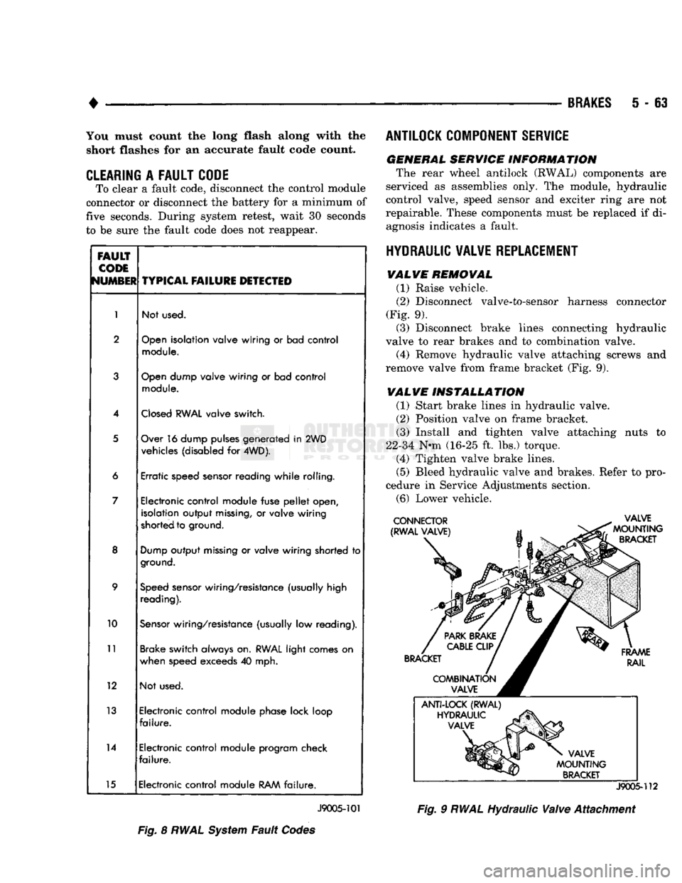
the number of times the amber antilock lamp flashes. Fault codes and typical malfunctions are outlined in Figure 8. Note that when a fault code is gen
erated, the red brake warning lamp will also
illuminate. The initial flash will be a long flash followed by a
number of short flashes. The long flash indicates the
beginning of the fault number sequence and the short flashes are a continuation of that sequence.
Page 250 of 1502
•
BRAKES
5 - 63 You must count the long flash along with the
short flashes for an accurate fault code count.
CLEARING
A
FAULT CODE
To clear a fault code, disconnect the control module
connector or disconnect the battery for a minimum of
five seconds. During system retest, wait 30 seconds
to be sure the fault code does not reappear.
FAULT
CODE
NUMBER
TYPICAL
FAILURE
DETECTED
1
Not used.
2
Open
isolation valve wiring
or
bad control
module.
3
Open
dump valve wiring
or
bad control
module.
4
Closed
RWAL
valve switch.
5
Over 16 dump pulses generated
in
2WD
vehicles (disabled
for
4WD).
6 Erratic speed sensor reading while rolling.
7 Electronic control module fuse
pellet
open,
isolation output
missing,
or
valve wiring
shorted to ground.
8
Dump
output
missing
or
valve wiring shorted
to
ground.
9
Speed
sensor wiring/resistance (usually high
reading).
10
Sensor
wiring/resistance (usually
low
reading).
11
Brake switch always on.
RWAL
light comes
on
when speed exceeds
40
mph.
12 Not used.
13 Electronic control module phase lock loop
failure.
14 Electronic control module program check
failure.
15 Electronic control module
RAM
failure.
J9005-101
Fig.
8
RWAL
System
Fault
Codes ANTILOCK COMPONENT SERVICE
GENERAL SERVICE INFORMATION
The rear wheel antilock (RWAL) components are
serviced as assemblies only. The module, hydraulic
control valve, speed sensor and exciter ring are not
repairable. These components must be replaced if di agnosis indicates a fault.
HYDRAULIC VALVE REPLACEMENT VALVE REMOVAL
(1) Raise vehicle.
(2)
Disconnect valve-to-sensor harness connector
(Fig. 9). (3) Disconnect brake lines connecting hydraulic
valve to rear brakes and to combination valve.
(4) Remove hydraulic valve attaching screws and
remove valve from frame bracket (Fig. 9).
VALVE INSTALLATION
(1) Start brake lines in hydraulic valve.
(2)
Position valve on frame bracket. (3) Install and tighten valve attaching nuts to
22-34 N-m (16-25 ft. lbs.) torque. (4) Tighten valve brake lines.
(5)
Bleed hydraulic valve and brakes. Refer to pro
cedure in Service Adjustments section.
(6)
Lower vehicle.
J9005-112
Fig.
9
RWAL
Hydraulic
Valve
Attachment
Page 251 of 1502
5
- 64
BRAKES
•
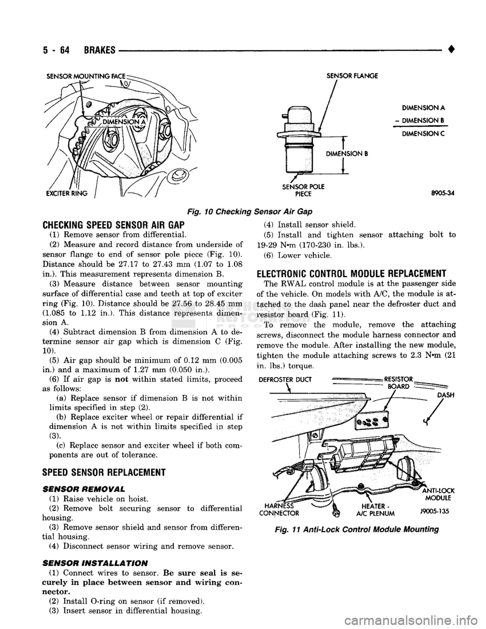
Fig.
10
Checking
CHECKING SPEED SENSOR
AIR GAP (1) Remove sensor from differential.
(2) Measure and record distance from underside of
sensor flange to end of sensor pole piece (Fig. 10).
Distance should be 27.17 to 27.43 mm (1.07 to 1.08
in.).
This measurement represents dimension B.
(3) Measure distance between sensor mounting
surface of differential case and teeth at top of exciter
ring (Fig. 10). Distance should be 27.56 to 28.45 mm (1.085 to 1.12 in,). This distance represents dimen
sion A.
(4) Subtract dimension B from dimension A to de
termine sensor air gap which is dimension C (Fig.
10).
(5) Air gap should be minimum of 0.12 mm (0.005
in.) and a maximum of 1.27 mm (0.050 in.). (6) If air gap is not within stated limits, proceed
as follows: (a) Replace sensor if dimension B is not within
limits specified in step (2). (b) Replace exciter wheel or repair differential if
dimension A is not within limits specified in step
(3).
(c) Replace sensor and exciter wheel if both com
ponents are out of tolerance.
SPEED
SENSOR REPLACEMENT
SENSOR
REMOVAL
(1) Raise vehicle on hoist.
(2) Remove bolt securing sensor to differential
housing.
(3) Remove sensor shield and sensor from differen
tial housing. (4) Disconnect sensor wiring and remove sensor.
SENSOR
INSTALLATION
(1) Connect wires to sensor. Be sure seal is se
curely in place between sensor and wiring con
nector. (2) Install O-ring on sensor (if removed). (3) Insert sensor in differential housing.
SENSOR
FLANGE
DIMENSION A
-
DIMENSION
B
DIMENSION C
SENSOR
POLE
PIECE
8905-34
Sensor
Air Gap (4) Install sensor shield.
(5) Install and tighten sensor attaching bolt to
19-29 Nnn (170-230 in. lbs.).
(6) Lower vehicle.
ELECTRONIC CONTROL MODULE REPLACEMENT
The RWAL control module is at the passenger side
of the vehicle. On models with A/C, the module is at
tached to the dash panel near the defroster duct and
resistor board (Fig. 11). To remove the module, remove the attaching
screws, disconnect the module harness connector and
remove the module. After installing the new module,
tighten the module attaching screws to 2.3 N»m (21 in. lbs.) torque.
Fig.
11
Anti-Lock
Control
Module
Mounting
Page 384 of 1502
•
INSTRUMENT PANEL
AND
GAUGES
8E - 3
MALFUNCTION INDICATOR (CHECK ENGINE)
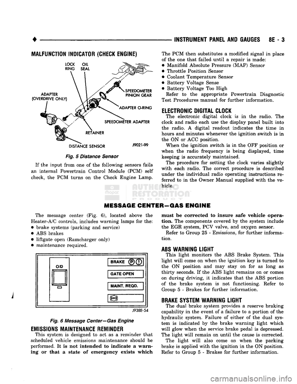
Fig.
5
Distance Sensor
If
the
input from
one of the
following sensors fails
an internal Powertrain Control Module
(PCM)
self
check,
the PCM
turns
on the
Check Engine Lamp. The
PCM
then substitutes
a
modified signal
in
place
of
the one
that failed until
a
repair
is
made:
• Manifold Absolute Pressure (MAP) Sensor
• Throttle Position Sensor
• Coolant Temperature Sensor
• Battery Voltage Sense
• Battery Voltage
Too
High
Refer
to the
appropriate Powertrain Diagnostic
Test Procedures manual
for
further information.
ELECTRONIC DIGITAL CLOCK
The electronic digital clock
is in the
radio.
The
clock
and
radio each
use the
display panel built into
the radio.
A
digital readout indicates
the
time
in
hours
and
minutes whenever
the
ignition switch
is in
the
ON or ACC
position. When
the
ignition switch
is in the OFF
position
or
when
the
radio frequency
is
being displayed, time keeping
is
accurately maintained. The procedure
for
setting
the
clock varies slightly
with each radio.
The
correct procedure
is
described under
the
individual radio operating instructions
re
ferred
to in the
Owner Manual supplied with
the ve
hicle.
MESSAGE CENTER—GAS ENGINE
The message center
(Fig. 6),
located above
the
Heater-A/C controls, includes warning lamps
for the:
• brake systems (parking
and
service)
•
ABS
brakes • liftgate open (Ramcharger only)
• maintenance required.
O/D
BRAKE
(P)(7
GATE OPEN
MAINT
REQD.
J938E-54
Fig.
6
Message Center—Gas Engine
EMISSIONS
MAINTENANCE REMINDER
This system
is
designed
to act as a
reminder that
scheduled vehicle emissions maintenance should
be
performed.
It is not
intended
to
indicate
a
warn
ing
or
that
a
state
of
emergency exists which must
be
corrected
to
insure safe vehicle opera
tion.
The
components covered
by the
system include
the
EGR
system,
PCV
valve,
and
oxygen sensor. Refer
to
Group
25 -
Emissions,
for
further informa
tion.
ABS
WARNING
LIGHT
This light monitors
the ABS
Brake System. This
light will come
on
when
the
ignition
key is
turned
to
the
ON
position
and may
stay
on for as
long
as
thirty seconds.
If the ABS
light remains
on or
comes on during driving,
it
indicates that
the ABS
portion
of
the
brake system
is not
functioning. Refer
to
Group
5 -
Brakes
for
further information.
BRAKE
SYSTEM WARNING
LIGHT
The dual brake system provides
a
reserve braking
capability
in the
event
of a
failure
to a
portion
of the
hydraulic system. Failure
of
either
of the
dual sys
tem
is
indicated
by the
brake warning light which
will glow when
the
service brake pedal
is
depressed.
The light will remain
on
until
the
cause
is
corrected. The light will also come
on
when
the
parking
brake
is
applied with
the
ignition
in the ON
position.
Refer
to
Group
5 -
Brakes
for
further information.
Page 385 of 1502
8E
- 4
INSTRUMENT PANEL
AND
GAUGES
•
MESSAGE CENTER—DIESEL
ENGINE
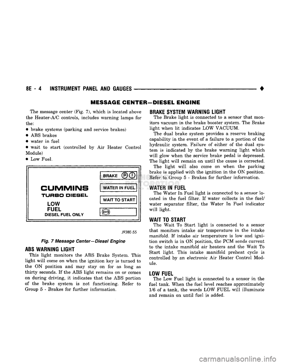
The message center (Fig. 7), which
is
located above
the Heater-A/C controls, includes warning lamps
for
the:
• brake systems (parking
and
service brakes)
• ABS brakes
• water
in
fuel
• wait
to
start (controlled
by Air
Heater Control
Module)
• Low Fuel.
BRAKE
CUMMINS
TURBO
DIESEL,
LOW
FUEL
DIESEL
FUEL ONLY WATER
IN
FUEL
WAIT
TO
START
J938E-55
Fig.
7
Message Center—Diesel Engine
ABS
WARNING LIGHT
This light monitors
the
ABS Brake System. This
light will come
on
when the ignition key
is
turned
to
the
ON
position
and may
stay
on for as
long
as
thirty seconds.
If
the ABS light remains
on or
comes
on during driving,
it
indicates that
the
ABS portion
of
the
brake system
is not
functioning. Refer
to
Group
5 -
Brakes
for
further information.
BRAKE
SYSTEM WARNING LIGHT
The Brake light
is
connected
to a
sensor that mon
itors vacuum
in
the brake booster system. The Brake
light when
lit
indicates LOW VACUUM. The dual brake system provides
a
reserve braking
capability
in
the event
of a
failure
to a
portion
of
the
hydraulic system. Failure
of
either
of the
dual sys
tem
is
indicated
by the
brake warning light which
will glow when
the
service brake pedal
is
depressed.
The light will remain
on
until
the
cause
is
corrected. The light will also come
on
when
the
parking
brake
is
applied with the ignition
in
the ON position. Refer
to
Group
5 -
Brakes
for
further information.
WATER
IN
FUEL
The Water
In
Fuel light
is
connected
to a
sensor lo
cated
in the
fuel filter.
If
water collects
in the
fuel/
water separator filter,
the
Water
In
Fuel indicator
will light.
WAIT
TO
START
The Wait
To
Start light
is
connected
to a
sensor
that monitors intake
air
temperature
in the
intake
manifold.
If
intake
air
temperature
is low and
igni
tion switch
is in
ON position,
the
PCM sends current
to
the
intake manifold
air
heaters
and the
Wait
To
Start light. This intake manifold preheat cycle
is
controlled
by an
electronic
Air
Heater Control Mod
ule.
LOW FUEL
The Low Fuel light
is
connected
to a
sensor
in the
fuel tank. When the fuel level reaches approximately 1/6
of a
tank,
the
words LOW FUEL will illuminate
and remain
on
until fuel
is
added.
Page 389 of 1502
8E
- 8 INSTRUMENT PANEL AND GAUGES
•
BRAKE
WARNING
LAMP
SWITCH TO BRAKE
WARNING LAMP
PR!
451
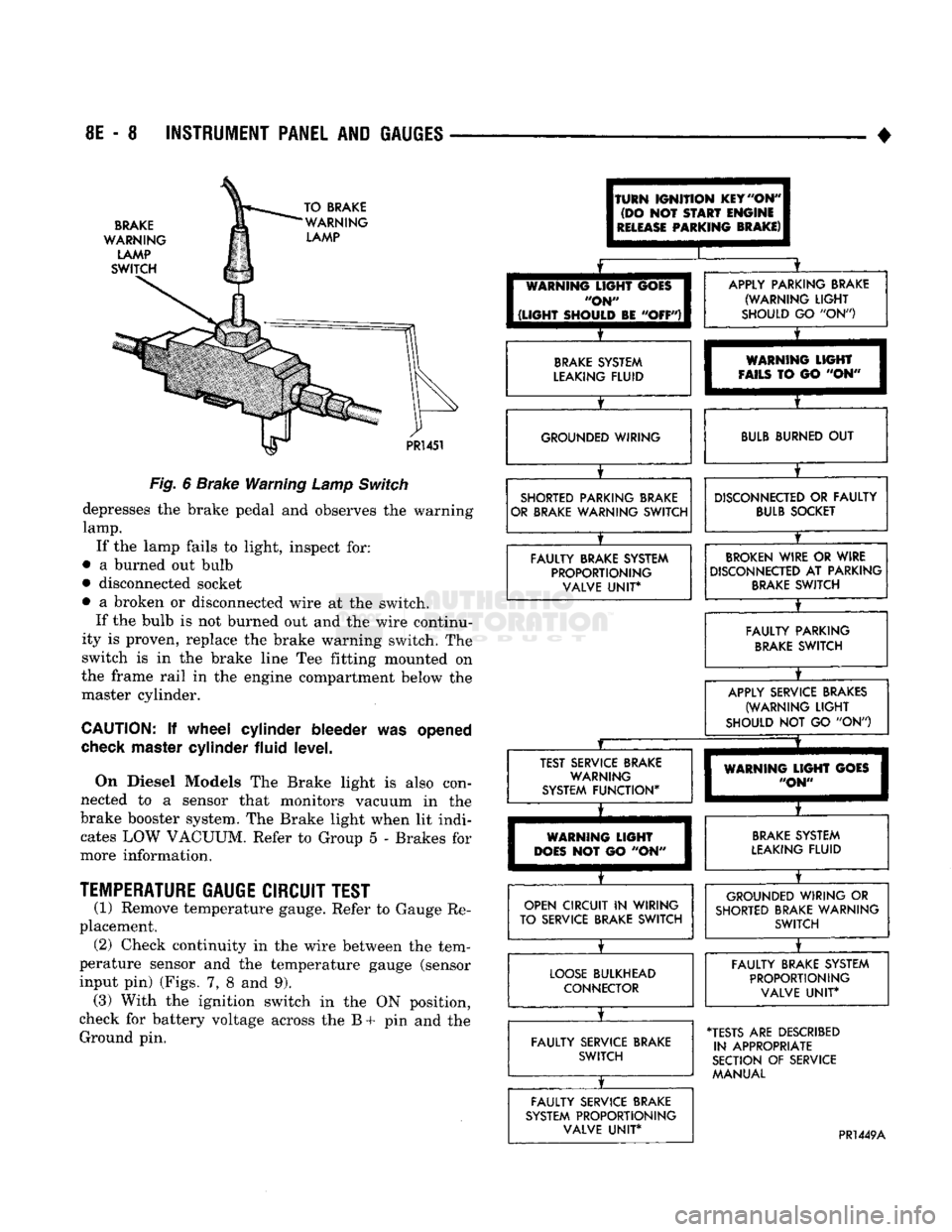
Fig.
6
Brake Warning
Lamp
Switch
depresses
the
brake pedal
and
observes
the
warning
lamp.
If
the
lamp fails
to
light, inspect
for:
•
a
burned
out
bulb
• disconnected socket
•
a
broken
or
disconnected wire
at the
switch. If
the
bulb
is not
burned
out and the
wire continu
ity
is
proven, replace
the
brake warning switch.
The
switch
is in the
brake line
Tee
fitting mounted
on
the frame rail
in the
engine compartment below
the
master cylinder.
CAUTION:
If
wheel cylinder bleeder
was
opened
check
master cylinder fluid level.
On Diesel Models
The
Brake light
is
also con
nected
to a
sensor that monitors vacuum
in the
brake booster system.
The
Brake light when
lit
indi cates
LOW
VACUUM. Refer
to
Group
5 -
Brakes
for
more information.
TEMPERATURE
GAUGE CIRCUIT TEST
(1) Remove temperature gauge. Refer
to
Gauge
Re
placement. (2) Check continuity
in the
wire between
the
tem
perature sensor
and the
temperature gauge (sensor
input
pin)
(Figs.
7, 8 and 9).
(3) With
the
ignition switch
in the ON
position,
check
for
battery voltage across
the B + pin and the
Ground
pin.
(TURN
IGNITION
KEY
"ON"
(DO
NOT
START
ENGINE
I
RELEASE
PARKING
BRAKE)
I
I
[
WARNING
LIGHT
GOES
I
"ON"
I
1
(LIGHT
SHOULD
BE
"OFF")!
X
APPLY PARKING BRAKE (WARNING
LIGHT
SHOULD
GO "ON")
BRAKE
SYSTEM
LEAKING FLUID
X
WARNING
LIGHT
FAILS
TO GO "ON" GROUNDED WIRING
BULB
BURNED
OUT
SHORTED PARKING BRAKE
OR BRAKE WARNING SWITCH
X
DISCONNECTED
OR
FAULTY
BULB
SOCKET
FAULTY BRAKE SYSTEM PROPORTIONING VALVE
UNIT*
BROKEN
WIRE
OR
WIRE
DISCONNECTED
AT
PARKING
BRAKE
SWITCH
X
FAULTY PARKING
BRAKE
SWITCH
X
APPLY SERVICE BRAKES
(WARNING
LIGHT
SHOULD
NOT GO "ON")
JZ
X
TEST SERVICE BRAKE WARNING
SYSTEM FUNCTION*
X
WARNING
LIGHT
GOES
"ON"
WARNING
LIGHT
DOES
NOT GO "ON"
BRAKE
SYSTEM
LEAKING FLUID
OPEN CIRCUIT
IN
WIRING
TO SERVICE BRAKE SWITCH
X
GROUNDED WIRING
OR
SHORTED BRAKE WARNING SWITCH
LOOSE
BULKHEAD CONNECTOR
X
FAULTY BRAKE SYSTEM
PROPORTIONING VALVE
UNIT*
FAULTY SERVICE BRAKE SWITCH
X
•TESTS
ARE
DESCRIBED
IN APPROPRIATE
SECTION
OF
SERVICE MANUAL
FAULTY SERVICE BRAKE
SYSTEM PROPORTIONING VALVE
UNIT*
PR1449A
Page 419 of 1502
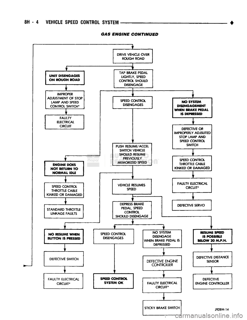
8H - 4 VEHICLE
SPEED
CONTROL SYSTEM
GAS
ENGINE
CONTINUED
UNIT
DISENGAGES
ON ROUGH ROAD
IMPROPER
ADJUSTMENT OF STOP LAMP AND SPEED
CONTROL SWITCH*
FAULTY
ELECTRICAL CIRCUIT
£
ENGINE DOES
NOT RETURN TO NORMAL IDLE
SPEED
CONTROL
THROTTLE
CABLE
KINKED OR DAMAGED
STANDARD
THROTTLE
LINKAGE FAULTS 1
DRIVE VEHICLE OVER
ROUGH ROAD
TAP BRAKE PEDAL
LIGHTLY,
SPEED
CONTROL SHOULD
DISENGAGE
SPEED
CONTROL
DISENGAGES
PUSH RESUME/ACCEL SWITCH VEHICLE
SHOULD RESUME PREVIOUSLY
MEMORIZED SPEED
VEHICLE RESUMES
SPEED
DEPRESS
BRAKE
PEDAL,
SPEED CONTROL
SHOULD DISENGAGE NO SYSTEM
DISENGAGEMENT
WHEN MAKE PEDAL
IS
DEPRESSED
DEFECTIVE OR
IMPROPERLY ADJSUTED
STOP LAMP AND
SPEED
CONTROL SWITCH
y
f
SPEED
CONTROL
THROTTLE
CABLE
KINKED OR DAAAAGED
1
FAULTY
ELECTRICAL CIRCUIT*
f
DEFECTIVE SERVO NO RESUME WHEN
BUTTON
IS
PRESSED
SPEED
CONTROL
DISENGAGES
DEFECTIVE SWITCH
FAULTY
ELECTRICAL CIRCUIT* NO SYSTEM
DISENGAGE
WHEN BRAKE PEDAL IS
DEPRESSED
SPEED
CONTROL
SYSTEM OK
1
f
DEFECTIVE ENGINE CONTROLLER
1
FAULTY
ELECTRICAL CIRCUIT*
r
STICKY BRAKE SWITCH RESUM
ISPO
BELOW
2
E
SPEED
SSIBLE
10
M.P.H.
y t
DEFECTIVE DISTANCE
SENSOR
y f
DEFECTIVE
ENGINE CONTROLLER
J928H-14
Page 421 of 1502
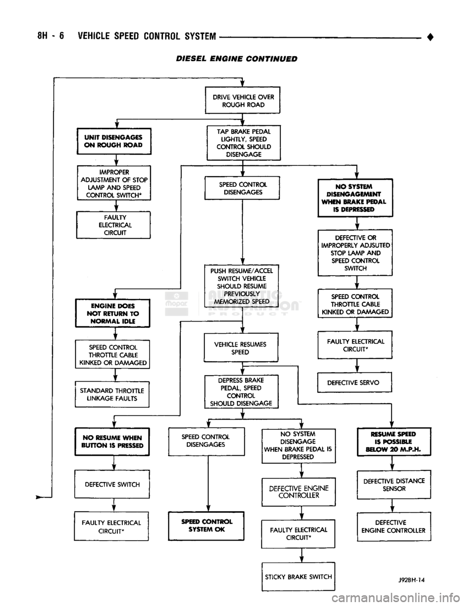
- 6
VEHICLE SPEED CONTROL SYSTEM
• £
UNIT
DISENGAGES
ON ROUGH ROAD
IMPROPER
ADJUSTMENT
OF
STOP LAMP AND SPEED
CONTROL SWITCH*
i
FAULTY
ELECTRICAL CIRCUIT
ENGINE DOES
NOT RETURN
TO
NORMAL IDLE
SPEED
CONTROL
THROTTLE
CABLE
KINKED OR DAAAAGED
STANDARD
THROTTLE
LINKAGE FAULTS
NO RESUME WHEN
BUTTON
IS
PRESSED
DRIVE VEHICLE OVER
ROUGH ROAD
±
TAP BRAKE PEDAL
LIGHTLY,
SPEED
CONTROL SHOULD
DISENGAGE
SPEED
CONTROL
DISENGAGES
PUSH RESUME/ACCEL SWITCH VEHICLE
SHOULD RESUME PREVIOUSLY
MEMORIZED SPEED
VEHICLE RESUMES
SPEED
DEPRESS
BRAKE
PEDAL,
SPEED CONTROL
SHOULD DISENGAGE NO SYSTEM
DISENGAGEMENT
WHEN MAKE PEDAL
IS
DEPRESSED
DEFECTIVE OR
IMPROPERLY ADJSUTED STOP LAMP
AND
SPEED
CONTROL SWITCH
1
1
SPEED
CONTROL
THROTTLE
CABLE
KINKED
OR
DAAAAGED
1
FAULTY
ELECTRICAL CIRCUIT*
1
DEFECTIVE SERVO
SPEED
CONTROL
DISENGAGES
DEFECTIVE SWITCH
FAULTY
ELECTRICAL CIRCUIT*
1
NO SYSTEM
DISENGAGE
WHEN BRAKE PEDAL
IS
DEPRESSED
SPEED
CONTROL
SYSTEM
OK
1
r
DEFECTIVE ENGINE CONTROLLER
* r
FAULTY
ELECTRICAL CIRCUIT*
r
STICKY BRAKE SWITCH RESUM
ISPO
BELOW*
E
SPEED
SSIBLE
10
M.P.H.
1
DEFECTIVE DISTANCE
SENSOR
f
DEFECTIVE
ENGINE CONTROLLER
J928H-14 DIESEL ENGINE CONTINUED