brake sensor DODGE TRUCK 1993 Service Service Manual
[x] Cancel search | Manufacturer: DODGE, Model Year: 1993, Model line: TRUCK, Model: DODGE TRUCK 1993Pages: 1502, PDF Size: 80.97 MB
Page 874 of 1502
•
FUEL
SYSTEM
14 - 55
Fig.
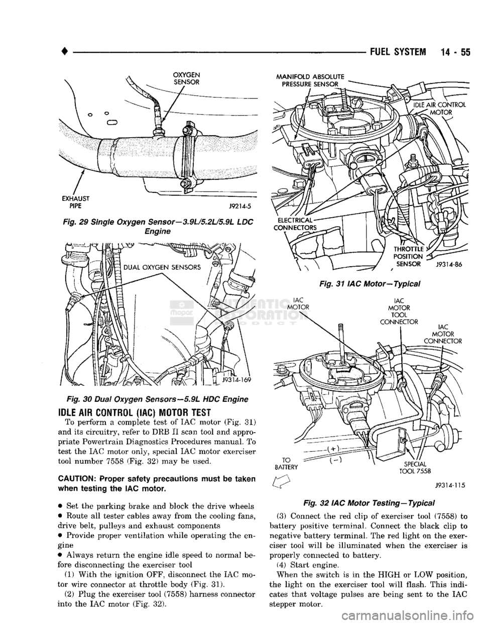
30
Dual
Oxygen
Sensors—5.9L
HDC
Engine
IDLE
AIR
CONTROL
(IAC)
MOTOR
TEST
To perform a complete test of IAC motor (Fig. 81)
and its circuitry, refer to DRB II scan tool and appro
priate Powertrain Diagnostics Procedures manual. To
test the IAC motor only, special IAC motor exerciser tool number 7558 (Fig. 32) may be used.
CAUTION:
Proper safety precautions must be
taken
when
testing
the IAC
motor,
• Set the parking brake and block the drive wheels
• Route all tester cables away from the cooling fans,
drive belt, pulleys and exhaust components
• Provide proper ventilation while operating the en
gine
• Always return the engine idle speed to normal be
fore disconnecting the exerciser tool
(1) With the ignition OFF, disconnect the IAC mo
tor wire connector at throttle body (Fig. 31).
(2) Plug the exerciser tool (7558) harness connector
into the IAC motor (Fig. 32).
MANIFOLD
ABSOLUTE
Fig.
31 IAC Motor—Typical
Fig.
32 IAC Motor
Testing—
Typical
(3) Connect the red clip of exerciser tool (7558) to
battery positive terminal. Connect the black clip to
negative battery terminal. The red light on the exer
ciser tool will be illuminated when the exerciser is
properly connected to battery. (4) Start engine.
When the switch is in the HIGH or LOW position,
the light on the exerciser tool will flash. This indi cates that voltage pulses are being sent to the IAC
stepper motor.
Page 883 of 1502
MULTI-PORT
FUEL
INJECTION
(MPI)-COMPONENT
REMOVAL/INSTALLATION
—EXCEPT DIESEL
INDEX
page
Accelerator Pedal
and Throttle
Cable
. 64
Air Conditioning (A/C) Clutch Relay
64
Air
Filter/Filter
Housing
64
Automatic Shut Down (ASD) Relay
. 64
Brake
Switch
64
Camshaft
Position
Sensor
..................
64
Charge
Air
Temperature
Sensor
64
Crankshaft Position
Sensor
64
Engine
Coolant Temperature
Sensor
65
EVAP
Canister Purge Solenoid
65
Fuel
Filter
65
Fuel Filter/Fuel Pressure Regulator—5.9L Engine
. 65
Fuel Injector(S)
67
Fuel Pressure Regulator
67
Fuel Pump Module
68
Fuel Pump Relay
68
ACCELERATOR
PEDAL
AND THROTTLE
CABLE
Refer
to
the
Accelerator Pedal
and
Throttle Cable
section
of
this group
for
removal/installation proce
dures.
AIR
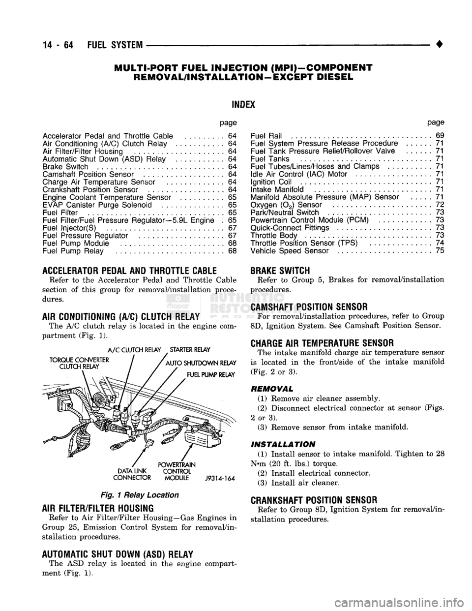
CONDITIONING (A/C) CLUTCH RELAY The A/C clutch relay
is
located
in
the
engine com
partment (Fig.
1).
A/C CLUTCH RELAY STARTER RELAY
DATA LINK CONTROL
CONNECTOR MODULE
J9314-164
Fig.
1 Relay Location
AIR
FILTER/FILTER
HOUSING
Refer
to
Air Filter/Filter Housing—Gas Engines
in
Group
25,
Emission Control System
for
removal/in
stallation procedures.
AUTOMATIC SHUT DOWN (ASD) RELAY The ASD relay
is
located
in
the
engine compart
ment (Fig.
1).
page
Fuel Rail
69
Fuel System Pressure Release Procedure
......
71
Fuel Tank Pressure Relief/Rollover Valve
71
Fuel Tanks
71
Fuel
Tubes/Lines/Hoses
and
Clamps
71
Idle
Air
Control (IAC) Motor
71
Ignition Coil
71
Intake Manifold
71
Manifold Absolute Pressure (MAP)
Sensor
71
Oxygen
(02)
Sensor
72
Park/Neutral Switch
. 73
Powertrain Control Module (PCM)
73
Quick-Connect
Fittings
73
Throttle
Body
73
Throttle
Position
Sensor
(TPS)
......
74
Vehicle
Speed
Sensor
75
BRAKE
SWITCH
Refer
to
Group
5,
Brakes
for
removal/installation
procedures.
CAMSHAFT
POSITION
SENSOR
For removal/installation procedures, refer
to
Group
8D,
Ignition System. See Camshaft Position Sensor.
CHARGE
AIR
TEMPERATURE SENSOR
The intake manifold charge
air
temperature sensor
is located
in the
front/side
of
the
intake manifold (Fig.
2
or
3).
REMOVAL
(1) Remove
air
cleaner assembly.
(2) Disconnect electrical connector
at
sensor (Figs.
2
or
3). (3) Remove sensor from intake manifold.
INSTALLATION
(1) Install sensor
to
intake manifold. Tighten
to 28
Nnn (20
ft.
lbs.) torque.
(2) Install electrical connector.
(3) Install
air
cleaner.
CRANKSHAFT
POSITION
SENSOR
Refer
to
Group 8D, Ignition System
for
removal/in
stallation procedures.
Page 895 of 1502
DIESEL
FUEL
INJECTION—COMPONENT
DESCRIPTION/SYSTEM
OPERATION
NDEX
page
Air
Conditioning (A/C) Clutch
Relay-PCM
Output
. 81
Air
Conditioning (A/C)
Controls-PCM
Input
.... 77
Air
Intake Heater
Relays—PCM
Output
........ 81
Auto
Shut
Down
(ASD)
Relay-PCM
Output
.... 82
Automatic
Shut
Down
(ASD)
Sense-PCM
input
. 78
Battery
Voltage-PCM
Input
78
Brake
Switch—PCM
Input
....... 78
Charge
Air
Temperature
Sensor—PCM
Input
... 78
Engine
Speed
Sensor—PCM
Input
........... 78
Fuel
Drain Manifold
83
Fuel
Heater
83
Fuel
Injection
Pump
83
Fuel
Injectors
84
Fuel
Solenoid
84
Fuel/Water
Separator
Filter ................. 84
General
Information
76
Generator
Field-PCM
Output
. 81
High
Pressure
Fuel
Lines
85
Ignition
Sense—PCM
Input
78
KSB
Solenoid
....... 85
Malfunction Indicator
Lamp—PCM
Output
...... 82
Manual
Shut
Down
Lever
.................. 85
GENERAL
INFORMATION
The fuel system of the 5.9L (in-line six-cylinder)
turbo-diesel engine (Fig. 1) consists of the following components:
• Fuel tank
• Low and high pressure fuel supply lines
• Mechanical lift pump
• Fuel/water separator filter
• Fuel heater
• Fuel injection pump
• Fuel injectors • Fuel return lines For information regarding fuel requirements of the
5.9L turbo-diesel engine, refer to the Fuel Require
ments—Diesel Engines paragraph at the front of this group. Although various components, relays and switches
are operated by the powertrain control module (PCM), the diesel fuel injection system (Fig. 1) is not
directly regulated by the PCM. Refer to the proceed
ing Powertrain Control Module section for additional
information.
SYSTEM
DIAGNOSIS
The PCM tests many of its own input and output
circuits. If a diagnostic trouble code (DTC) is found in a major system, this information is stored in the
PCM memory. Refer to On-Board Diagnostics in the Diesel Fuel Injection—General Diagnosis section of
page
Mechanical
Lift
Pump
86
Overdrive
Indicator
Lamp—PCM
Output
....... 82
Overdrive
Solenoid-PCM
Output
............ 82
Overdrive/Override
Switch—PCM
Input
........ 79
Park/Neutral
Switch-PCM
Input
79
Power
Ground-PCM
Input
. 79
Powertrain Control Module
(PCM)
76
SCI
Receive-PCM
Input
. . 80
SCI
Transmit-PCM
Output
. . . 82
Sensor
Return-PCM
Input
................. 80
Signal
Ground-PCM
Input
. 80
Speed
Control-PCM
Input
80
Speed
Control-PCM
Output
82
System
Diagnosis
76
System
Operation
86
Tachometer-PCM
Output
82
Throttle
Position
Sensor
(TPS)-PCM
Input
80
Vehicle
Speed
Sensor-PCM
Input
80
Wait-To-Start
Lamp-PCM
Output
82
Water-ln-Fuel
Lamp-PCM
Output
83
Water-ln-Fuel
Sensor-PCM
input
80
this group for DTC information. The DRB II scan tool can be used to access the DTC messages stored in the PCM memory.
POWERTRAIN
CONTROL
MODULE
(PCM)
The powertrain control module (PCM) (Fig. 2) was
formerly referred to as the SBEC or engine control ler. The PCM is a pre-programmed, dual micropro
cessor digital computer. The PCM is located in the engine compartment be
hind the battery and under the left front fender (Fig.
2).
The PCM contains a voltage convertor, which con
verts battery voltage to a regulated 8.0 volts. This is used to power the engine speed sensor. The PCM also
provides a 5 volt supply for the throttle position sensor (TPS). The TPS is not used if equipped with a
manual transmission.
Various sensors, switches and relays provide the
inputs necessary for operation of the PCM.
The PCM Inputs are from:
9
Air conditioning control switch
• Automatic shut down (ASD) sense circuit
• Battery voltage
• Brake light switch • Charge air temperature sensor ® Coolant temperature sensor (Auto, trans, only)
• Engine speed sensor
• Ignition
• Overdrive/override switch
• Park/neutral switch (Auto, trans, only)
Page 897 of 1502
14-78
FUEL SYSTEM
• If
the A/C low
pressure switch opens (indicating
a
low refrigerant level),
the PCM
will
not
receive
an
A/C select signal.
The PCM
will then remove
the
ground from
the A/C
relay. This will deactivate
the
A/C compressor clutch.
If evaporator switch opens, (indicating that evapo
rator
is not in
proper temperature range),
PCM
will
not receive
the A/C
request signal.
The PCM
will
then remove
the
ground from
the A/C
relay, deacti
vating
the A/C
compressor clutch.
AUTOMATIC SHUT DOWN
(ASD)
SENSE-PCM
INPUT
A
12
volt signal
at
this input indicates
to the PCM
that
the ASD has
been activated.
The ASD
relay
is
located
in the
engine compartment
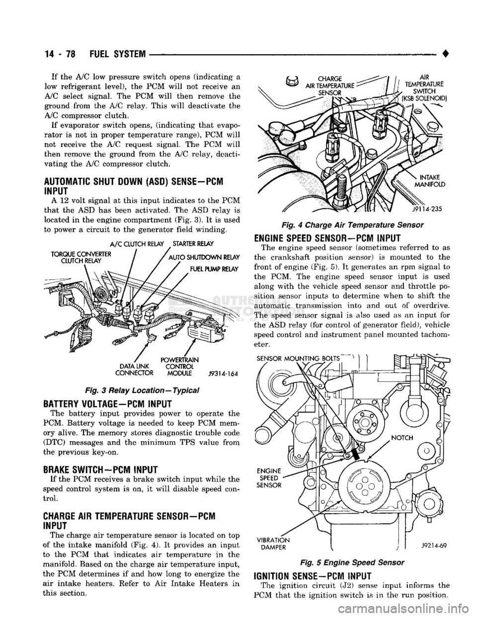
(Fig.
3).
It is
used
to power
a
circuit
to the
generator field winding.
TORQUE
CONVERTER
CLUTCH RELAY A/C
CLUTCH RELAY
.
STARTER RELAY
AUTO
SHUTDOWN
RELAY
FUEL PUMP RELAY
DATA
LINK
CONNECTOR
POWERTRAIN
CONTROL
MODULE
J9314-164
Fig.
3
Relay Location—Typical
BATTERY VOLTAGE-PC! INPUT
The battery input provides power
to
operate
the
PCM. Battery voltage
is
needed
to
keep
PCM
mem
ory alive.
The
memory stores diagnostic trouble code (DTC) messages
and the
minimum
TPS
value from
the previous key-on,
BRAKE
SWITCH-PCM INPUT
If
the PCM
receives
a
brake switch input while
the
speed control system
is on, it
will disable speed con
trol.
CHARGE AIR TEMPERATURE SENSOR—PCM INPUT
The charge
air
temperature sensor
is
located
on top
of
the
intake manifold
(Fig. 4). It
provides
an
input
to
the PCM
that indicates
air
temperature
in the
manifold. Based
on the
charge
air
temperature input,
the
PCM
determines
if and how
long
to
energize
the
air intake heaters. Refer
to Air
Intake Heaters
in
this section. AIR
TEMPERATURE
SWITCH
(KSB
SOLENOID)
j9114-235
Fig.
4
Charge
Air
Temperature Sensor
ENGINE
SPEED
SENSOR-PCM
INPUT
The engine speed sensor (sometimes referred
to as
the crankshaft position sensor)
is
mounted
to the
front
of
engine
(Fig. 5). It
generates
an rpm
signal
to
the
PCM. The
engine speed sensor input
is
used along with
the
vehicle speed sensor
and
throttle
po
sition sensor inputs
to
determine when
to
shift
the
automatic transmission into
and out of
overdrive.
The speed sensor signal
is
also used
as an
input
for
the
ASD
relay
(for
control
of
generator field), vehicle speed control
and
instrument panel mounted tachom
eter.
SENSOR
MOUNTING BOLTS
VIBRATION
DAMPER
J9214-69
Fig.
5
Engine Speed Sensor
IGNITION
SENSE-PCM
INPUT
The ignition circuit
(J2)
sense input informs
the
PCM that
the
ignition switch
is in the run
position.
Page 899 of 1502
14 - 80
FUEL SYSTEM
•
SCI
RECEIVE-PCM
INPUT
The serial communication interface (SCI) receive
and transmit outputs allow the PCM to communicate
with the DRB II scan tool.
SENSOR
RETURN-PCM
INPUT
Sensor return provides a low noise ground refer
ence for all system sensors.
SIGNAL
GROUND-PCM
INPUT
Provides a common ground for the input signals.
SPEED
CONTROL-PCM
INPUT
The PCM regulates the speed control system based
on inputs it receives. The speed control operating
range is from 35 to 85 mph. Inputs that effect speed control operation are:
• Park/neutral switch
• Vehicle speed sensor
• Throttle position sensor
• Engine speed sensor
• Brake switch
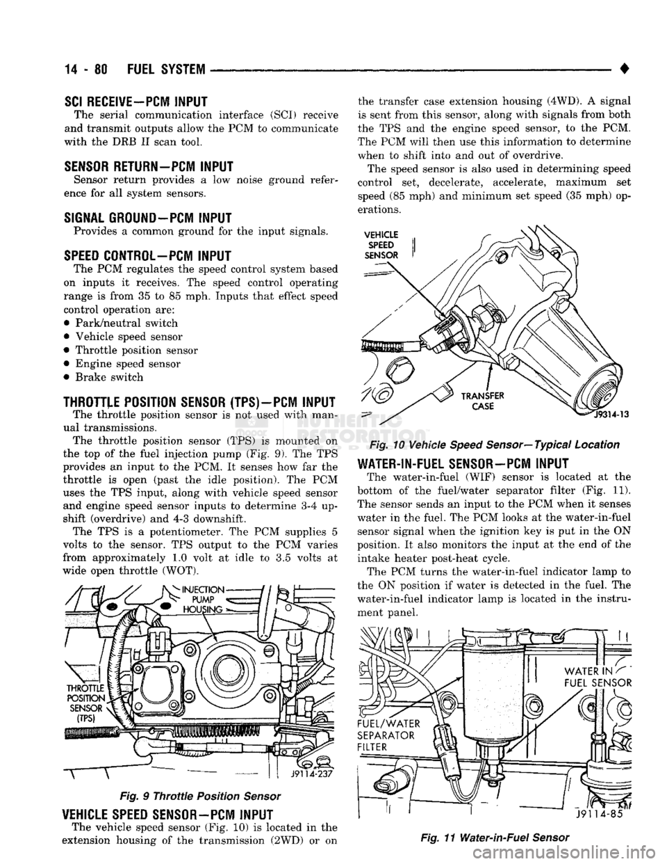
THROTTLE
POSITION SENSOR (TPS) —PCM
INPUT
The throttle position sensor is not used with man
ual transmissions. The throttle position sensor (TPS) is mounted on
the top of the fuel injection pump (Fig. 9). The TPS
provides an input to the PCM. It senses how far the
throttle is open (past the idle position). The PCM uses the TPS input, along with vehicle speed sensor and engine speed sensor inputs to determine 3-4 up
shift (overdrive) and 4-3 downshift. The TPS is a potentiometer. The PCM supplies 5
volts to the sensor. TPS output to the PCM varies
from approximately 1.0 volt at idle to 3.5 volts at
wide open throttle (WOT). T
J9114-237
Fig.
9
Throttle
Position
Sensor
VEHICLE SPEED SENSOR-PCM
INPUT
The vehicle speed sensor (Fig. 10) is located in the
extension housing of the transmission (2WD) or on the transfer case extension housing (4WD). A signal
is sent from this sensor, along with signals from both
the TPS and the engine speed sensor, to the PCM.
The PCM will then use this information to determine
when to shift into and out of overdrive.
The speed sensor is also used in determining speed
control set, decelerate, accelerate, maximum set
speed (85 mph) and minimum set speed (35 mph) op
erations.
VEHICLE
SPEED
SENSOR
Fig.
10 Vehicle
Speed
Sensor—Typical Location
WATER-IN-FUEL SENSOR-PCM
INPUT
The water-in-fuel (WIF) sensor is located at the
bottom of the fuel/water separator filter (Fig. 11). The sensor sends an input to the PCM when it senses
water in the fuel. The PCM looks at the water-in-fuel sensor signal when the ignition key is put in the ON
position. It also monitors the input at the end of the intake heater post-heat cycle. The PCM turns the water-in-fuel indicator lamp to
the ON position if water is detected in the fuel. The
water-in-fuel indicator lamp is located in the instru ment panel.
J91 14-85
Fig.
11 Water-in-Fuel
Sensor
Page 901 of 1502
14 - 82
FUEL 'SYSTEM
—. — ~—— — «
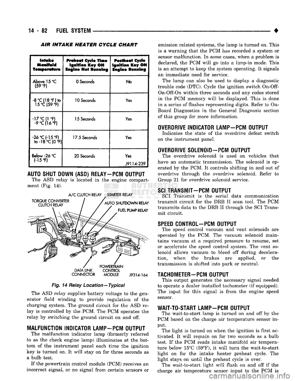
INTAKE HEATER CYCLE CHART
Intake
featperafwre
Preheat
Cycle
Time
Ignition
l£ey ON
Engine
Not
Running
Pestheat
Cycle
Ignition
Key ON
Snglne Running
Above
15
°C
(59
°F)
0 Seconds
No
-8°C(18°F)to
15°C (59
°F)
10
Seconds
Yes
-17°C(1
°F)
-9
°C(]6°F)
15
Seconds
Yes
«2d°C(-15°F)
to-18°C(0
°F) 17.5
Seconds
Yes
Below-26
°C (-15
*F)
20 Seconds
Yes
J9114-239
AUTO SHUT DOWN (ASD) RELAY-PCM OUTPUT
The ASD relay is located in the engine compart
ment (Fig. 14).
TORQUE CONVERTER
CLUTCH RELAY A/C CLUTCH RELAY STARTER RELAY
AUTO SHUTDOWN RELAY FUEL PUMP RELAY DATA LINK
CONNECTOR
POWERTRAIN
CONTROL MODULE
J9314-164
Fig.
14 Relay Location—Typical The ASD relay supplies battery voltage to the gen
erator field winding to provide regulation of the
charging system. The ground circuit for the ASD re
lay is controlled by the PCM. The PCM operates the
relay by switching the ground circuit on and off.
MALFUNCTION INDICATOR LAMP-PCM OUTPUT
The malfunction indicator lamp (formerly referred
to as the check engine lamp) illuminates at the bot
tom of the instrument panel each time the ignition
key is turned on. It will stay on for three seconds as
a bulb test. If the powertrain control module (PCM) receives an
incorrect signal, or no signal from certain sensors or emission related systems, the lamp is turned on. This
is a warning that the PCM has recorded a system or
sensor malfunction. In some cases, when a problem is
declared, the PCM will go into a limp-in mode. This is an attempt to keep the system operating. It signals
an immediate need for service.
The lamp can also be used to display a diagnostic
trouble code (DTC). Cycle the ignition switch
On-Off-
On-Off-On within three seconds and any codes stored
in the PCM memory will be displayed. This is done
in a series of flashes representing digits. Refer to On-
Board Diagnostics in the General Diagnosis section
of this group for more information.
OVERDRIVE
INDICATOR LAMP-PCM OUTPUT
Indicates the state of the overdrive defeat switch
on the instrument panel.
OVERDRIVE
S0LEN0ID-PCM OUTPUT
The overdrive solenoid is used on vehicles that
have an automatic transmission. The solenoid is op erated by the PCM. It controls shifting in and out of
overdrive through the overdrive solenoid. Refer to Group 21 for overdrive solenoid service.
SCI
TRANSMIT—PCM OUTPUT
SCI Transmit is the serial data communication
transmit circuit for the DRB II scan tool. The PCM
transmits data to the DRB II through the SCI Trans
mit circuit.
SPEED
C0NTR0L-PCM OUTPUT
The speed control vacuum and vent solenoids are
operated by the PCM. The vacuum solenoid main
tains vacuum at a required pressure to resume, set or accelerate the speed control system. The vent so
lenoid allows vacuum to bleed off during decelera
tion, when the brakes are applied, or the
transmission is shifted into park or neutral.
TACHOMETER-PCM
OUTPUT
This output generates the necessary signal needed
to operate a dealer installed tachometer (if equipped).
The input for this signal is from the engine speed sensor.
WAIT-TO-START LAMP-PCM OUTPUT
The wait-to-start lamp is turned on and off by the
PCM based on the charge air temperature sensor in
put. The light is turned on when the ignition is first ac
tivated. It will remain on for two seconds as a bulb
test. If the PCM reads intake manifold air tempera
ture below 15°C (59°F), it will turn the wait-to-start light on for the intake heater preheat cycle. The
light stays on until the preheat cycle is over. The wait-to-start light will flash on and off if the
charge air temperature sensor input to the PCM is
Page 906 of 1502
•
FUEL
SYSTEM
14 - 87
ENGINE
WARM-UP
• The PCM may start the air intake heater post-heat
cycle depending on intake air temperature. If manifold air temperature was at or below 15°C (59°F) when the
ignition switch was turned on, the cycle is started.
• If intake manifold air temperature is below 32°C
(90°F),
the KSB solenoid will be energized through
the air temperature switch. The solenoid remains en ergized until the air temperature switch opens. The
switch opens when intake manifold air temperature
is above 32°C (90°F).
• If the coolant temperature is below 16°C (60° F),
the transmission will not be allowed to enter over drive (automatic transmission).
• The PCM will turn on the water-in-fuel lamp if a signal is received from the water-in-fuel sensor.
CRUISE
OR
IDLE
• The PCM monitors intake manifold air tempera
ture through the charge temperature sensor input. • If intake manifold air temperature is below 32°C
(90°F),
the KSB solenoid will be energized through
the air temperature switch. The solenoid remains en ergized until the air temperature switch opens. The switch opens when intake manifold air temperature
is above 32°C (90°F).
• The air intake heater post-heat cycle will be com
pleted, if it is not already over.
• The vehicle speed sensor, engine speed sensor and
throttle position sensor inputs are used to control
transmission overdrive operation.
• If the coolant temperature is below 16° C (60° F),
the transmission will not be allowed to enter over drive (automatic transmission).
• If the transmission thermo-switch is open, the
transmission will not be allowed to enter into over
drive (automatic transmission). If the switch opens
when the vehicle is in overdrive, the transmission
will be downshifted. The transmission thermo-switch opens at 134°C (273°F).
• The thermo-switch will close once the transmission
fluid temperature drops to 116°C (240°F). • The PCM will turn on the water-in-fuel lamp if a signal is received from the water-in-fuel sensor.
ACCELERATION
• The vehicle speed sensor, engine speed sensor and
throttle position sensor inputs are used to control
transmission overdrive operation.
• If the coolant temperature is below 16° C (60° F),
the transmission will not be allowed to enter over
drive (automatic transmission).
• If intake manifold air temperature is below 32°C
(90°F),
the KSB solenoid will be energized through
the air temperature switch. The solenoid remains en ergized until the air temperature switch opens. The
switch opens when intake manifold air temperature
is above 32°C (90°F). • If the transmission thermo-switch is open, the
transmission will not be allowed to enter into over
drive (automatic transmission). If the switch opens
when the vehicle is in overdrive, the transmission
will be downshifted. The transmission thermo-switch opens at 134°C (273°F). The thermo-switch will close
once the transmission fluid temperature drops to 116°C (240°F).
• The PCM will turn on the water-in-fuel lamp if a
signal is received from the water-in-fuel sensor.
• If the speed control system resume/accelerate func
tion is being used, the PCM will only allow the vehi
cle to accelerate at a predetermined rate. If a speed
control has been set and the resume/accelerate but
ton is momentarily pushed in, the PCM will increase
vehicle speed by two miles per hour.
• If the brakes are applied, the PCM will disable the
speed control.
DECELERATION
• The vehicle speed sensor, engine speed sensor and
throttle position sensor inputs are used to control
transmission overdrive operation.
• If the coolant temperature is below 16° C (60° F),
the transmission will not be allowed to enter over drive (automatic transmission).
• If the transmission thermo-switch is open, the trans
mission will not be allowed to enter into overdrive (au
tomatic transmission). If the switch opens when the
vehicle is in overdrive, the transmission will be down shifted. The transmission thermo-switch opens at 134°C (273°F). The thermo-switch will close once the transmis
sion fluid temperature drops to 116°C (240°F).
• The PCM will turn on the water-in-fuel lamp if a
signal is received from the water-in-fuel sensor.
• If intake manifold air temperature is below 32°C
(90°F),
the KSB solenoid will be energized through
the air temperature switch. The solenoid remains en ergized until the air temperature switch opens. The
switch opens when intake manifold air temperature
is above 32°C (90°F).
• If the speed control system coast/set function is be
ing used, the PCM will only allow the vehicle to de celerate at a predetermined rate. If the coast/set
switch is pushed while the system is operating, the
PCM will set speed control to the rate the vehicle is
traveling at when the switch is released. • If the brakes are applied, the PCM will disable the speed control.
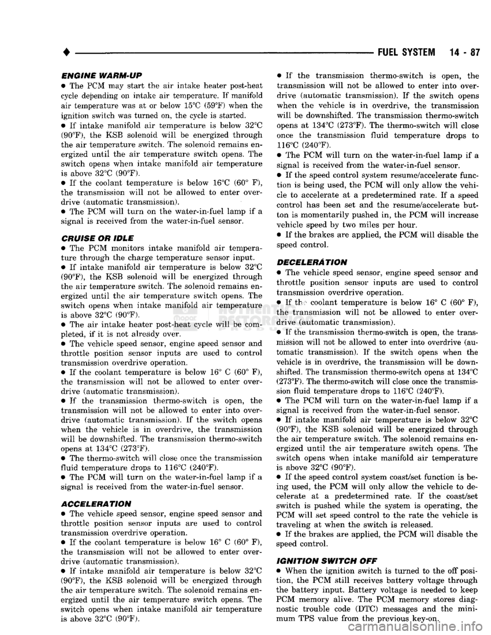
IGNITION SWITCH
OFF
• When the ignition switch is turned to the off posi
tion, the PCM still receives battery voltage through
the battery input. Battery voltage is needed to keep
PCM memory alive. The PCM memory stores diag nostic trouble code (DTC) messages and the mini
mum TPS value from the previous key-on.
Page 918 of 1502
CAV
WIRE
COLOR DESCRIPTION
CAV
WIRE
COLOR DESCRIPTION
1 WT/BK
WATER-IN-FUEL SENSOR 37 OVERDRIVE LAMP SIGNAL
2 TN/BK
COOLANT SENSOR (AUTOMATIC TRANSMISSION ONLY) 38
3 RD BATTERY
39
4
BK/LB*
SENSOR RETURN 40
5 BK/WT
SIGNAL GROUND 41
6 VT/WT*
5 VOLT SUPPLY 42
7 TN/YL 8 VOLT INPUT 43 GR/LB TACHOMETER
8 44
9 DB
IGNITION SENSE 45 LG DATA LINK RECIEVE
10 RD/WT*
OVERDRIVE OVERRIDE 46
11 BK/TN POWER GROUND
47 WT/OR* VEHICLE SENSOR
12 BK/TN
POWER GROUND 48 BR/RD* SPEED CONTROL COAST/SET SWITCH
13 49 YL/RD* SPEED CONTROL ON/OFF SWITCH
14 50 WT/LG* SPEED CONTROL RESUME/ACCEL SWITCH
15 OR/BK* HEATER
#2
RELAY 51 DB/YL ASD RELAY
16 YL/BK HEATER #1 RELAY 52
17 53 LG/RD* SPEED CONTROL VENT SOLENOID
18 54 BK/PK* WATER-IN-FUEL LAMP
19 55 OR/LG* OVERDRIVE SOLENOID
20 DG GENERATOR FIELD 56 DG/WT WAIT-TO-START LAMP
21 BK/RD
CHARGE (INTAKE) AIR TEMPERATURE SENSOR 57 DG/OR ASD SENSE
22
OR/DB*
THROTTLE POSITION SENSOR 58
23 59
24 GY/BK
REFERENCE PICKUP 60
25 PK
DATA LINK TRANSMIT WIRE COLOR CODES LB
LIGHT BLUE VT VIOLET
26 BK BLACK LG LIGHT GREEN WT
WHITE
27 BR
A/C CLUTCH REQUEST BR BROWN OR ORANGE
YL YELLOW
28 LG/RD THERMO SWITCH DB DARK BLUE PK PINK *
WITH TRACER
29 WT/PK* BRAKE SWITCH DG DARK GREEN
RD RED
30 BR/YL*
PARK/NEUTRAL SWITCH GY GRAY TN TAN
31 ruin
32 BK/PK*
MALFUNCTION INDICATOR LAMP
n
33 TN/RD*
SPEED CONTROL VACUUM SOLENOID CONNECTOR
J//000OOOOOOO
1 1
HI
173456789
10 J/^"*\
Hi
oooooooooo (1 Oj]
VlX
21
22
23
24
25
26
27
28
29
30
\V~V//
oooooooooo
\
II
12 13
14 15
16 17 18
19 20
\
34 DB/OR
WIDE OPEN THROTTLE (A/C) TERMINAL
J//000OOOOOOO
1 1
HI
173456789
10 J/^"*\
Hi
oooooooooo (1 Oj]
VlX
21
22
23
24
25
26
27
28
29
30
\V~V//
oooooooooo)}
31
32 33 34 35 36 37 38 39 40
1JU
35 SHOWN \\\
41 42 43 44 45 46 47 48 49
SO
1
^m^^
|
oooooooooo
1
1
oooooooooo
J//
36
Li
J9314-185
PCM
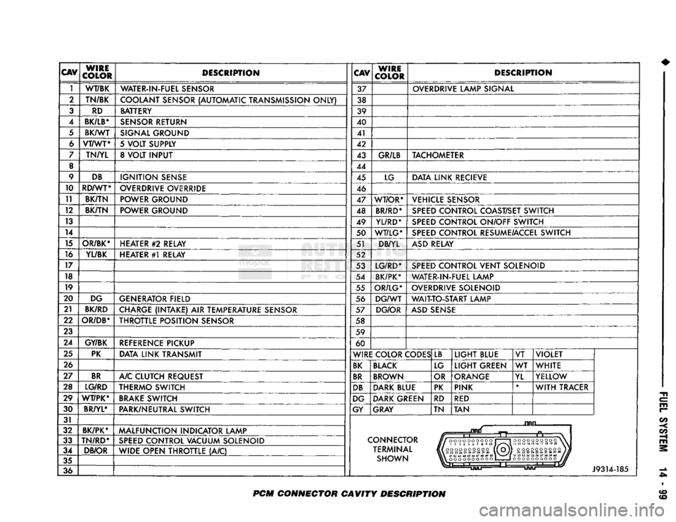
CONNECTOR CAVITY DESCRIPTION
Page 925 of 1502
14
- 106
FUEL SYSTEi
DIESEL FUEL
INJECTION-SERVICE
PROCEDURES
INDEX
page
Air Bleed Procedure
106
Air Fuel Control Tube
107
Air Intake Heater
107
Engine
Speed
Sensor
108
Fuel Drain Manifold
109
Fuel Heater
. 110
Fuel
Injection
Pump
110
Fuel
Injection
Pump Supply Line
114
Fuel
Injectors
114
AIR BLEED PROCEDURE
A certain amount
of air
becomes trapped
in the
fuel system when fuel system components
are
ser
viced
or
replaced. Bleed
the
system after fuel system service according
to the
following procedures.
WARNING:
DO NOT
BLEED
AIR
FROM
THE
FUEL
SYSTEM
OF
A
HOT
ENGINE.
DO
NOT
ALLOW FUEL
TO SPRAY ONTO
THE
EXHAUST MANIFOLD WHEN BLEEDING
AIR
FROM
THE
FUEL SYSTEM.
MANUAL BLEEDING
Some
air
enters
the
fuel system when
the
filters
or
injection pump supply line
are
changed. This small
amount
of air is
vented automatically from
the
injec
tion pump through
the
fuel drain manifold. This
is if
the filter
was
changed according
to
instructions.
The system will have
to be
bleed manually
if:
•
The
fuel filter
is not
filled before installation
•
Injection pump
is
replaced
•
High pressure fuel line connections
are
loosened
or
lines replaced
•
Initial engine start-up
or
start-up after
an ex
tended period
of no
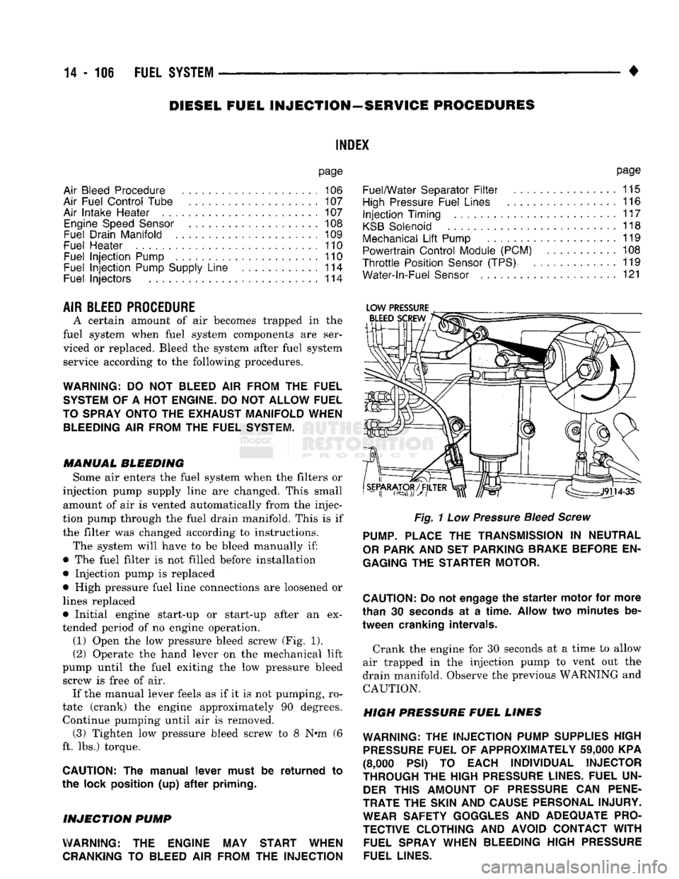
engine operation. (1) Open
the low
pressure bleed screw
(Fig. 1).
(2) Operate
the
hand lever
on the
mechanical lift
pump until
the
fuel exiting
the low
pressure bleed screw
is
free
of air.
If
the
manual lever feels
as if it is not
pumping,
ro
tate (crank)
the
engine approximately
90
degrees. Continue pumping until
air is
removed. (3) Tighten
low
pressure bleed screw
to 8 N»m (6
ft.
lbs.)
torque.
CAUTION:
The
manual lever must
be
returned
to
the lock position
(up) after
priming.
INJECTION
PUMP
WARNING:
THE
ENGINE
MAY
START WHEN
CRANKING
TO
BLEED
AIR
FROM
THE
INJECTION
page
Fuel/Water Separator
Filter
................
115
High
Pressure Fuel Lines
116
Injection
Timing
117
KSB
Solenoid
118
Mechanical
Lift
Pump
119
Powertrain Control Module (PCM)
108
Throttle
Position
Sensor
(TPS)
119
Water-ln-Fuel
Sensor
121
Fig.
1
Low
Pressure
Bleed Screw
PUMP.
PLACE
THE
TRANSMISSION
IN
NEUTRAL
OR
PARK
AND SET
PARKING BRAKE BEFORE
EN
GAGING
THE
STARTER MOTOR.
CAUTION:
Do
not
engage
the
starter
motor
for
more
than
30
seconds
at a
time.
Allow
two
minutes
be
tween cranking intervals.
Crank
the
engine
for 30
seconds
at a
time
to
allow
air trapped
in the
injection pump
to
vent
out the
drain manifold. Observe
the
previous WARNING
and
CAUTION.
HIGH PRESSURE FUEL LINES
WARNING:
THE
INJECTION PUMP SUPPLIES HIGH
PRESSURE
FUEL
OF
APPROXIMATELY
59,000
KPA
(8,000
PSI) TO
EACH INDIVIDUAL INJECTOR
THROUGH
THE
HIGH
PRESSURE
LINES. FUEL
UN
DER
THIS AMOUNT
OF
PRESSURE
CAN
PENE
TRATE
THE
SKIN
AND
CAUSE PERSONAL INJURY. WEAR SAFETY GOGGLES
AND
ADEQUATE PRO
TECTIVE CLOTHING
AND
AVOID CONTACT
WITH
FUEL SPRAY WHEN BLEEDING HIGH
PRESSURE
FUEL LINES.
Page 1480 of 1502
EMISSION
CONTROL SYSTEMS
25 - :
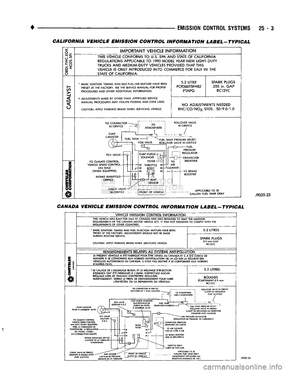
CALIFORNIA VEHICLE EMISSION CONTROL INFORMATION LABEL-TYPICAL
or,
o_ UJ
u_
U
^
>
CO
CQ
o
IMPORTANT
VEHICLE
INFORAAATION
THIS VEHICLE CONFORMS
TO
U.S.
EPA AND STATE
OF
CALIFORNIA REGULATIONS APPLICABLE
TO 1993
MODEL YEAR NEW
LIGHT-DUTY
TRUCKS
AND
MEDIUM-DUTY VEHICLES PROVIDED
THAT
THIS VEHICLE
IS
ONLY INTRODUCED
INTO
COMMERCE FOR
SALE
IN THE
STATE
OF
CALIFORNIA.
*
BASIC
IGNITION TIMING
AND
IDLE FUEL/AIR
MIXTURE HAVE BEEN
PRESET
AT THE
FACTORY.
SEE THE
SERVICE MANUAL
FOR
PROPER
PROCEDURES
AND
OTHER
ADDITIONAL
INFORMATION.
o
ADJUSTMENTS MADE
BY
OTHER
THAN
APPROVED
SERVICE MANUAL PROCEDURES
MAY
VIOLATE
FEDERAL
AND
STATE
LAWS.
CAUTION:
APPLY
PARKING BRAKE
WHEN
SERVICING
VEHICLE.
5.2
LITER
PCR360T5FHB2
PTAPG
SPARK
PLUGS
.035
in.
GAP RC12YC NO ADJUSTMENTS NEEDED
RHC/CO/NOx
STDS.
.50/9.0/1.0
TEE
CONNECTOR
W/ORIFICE
TO
ATMOSPHERE
ROLLOVER
VALVE
W/ORIFICE
/
PCV
VALVE-
TO
CLIMATE
CONTROL,
VEHICLE SPEED
CONTROL,
4X4
AXLE
(WHEN
EQUIPPED)
INTAKE
MANIFOLD"
ORIFICE
—
M
r-
M
EVAP
PURGE
SOLENOID
FILTER
THROTTLE
BODY
FUEL
TANK PRESSURE
RELIEF/
ROLLOVER
VALVE
W/ORIFICE
FUEL
PRESSURE
REGULATOR
1
r—O
O^-CRANKCASE
TO
AIR
CLEANER
APPLICABLE
TO
35
GALLON
FUEL
TANK
ONLY
J9325-23
CANADA VEHICLE EMISSION CONTROL INFORMATION LABEL-ATYPICAL
VEHICLE
EMISSION
CONTROL
INFORAAATION
THIS
VEHICLE
WAS
BUILT
FOR
SALE
IN
CANADA
AND WAS
DESIGNED
TO
MEET
THE
EMISSION
REQUIREMENTS
OF THE
CANADA
MOTOR
VEHICLE
ACT.
IT
WAS NOT
DESIGNED
TO
COMPLY
WITH
THE
REQUIREMENTS
OF
OTHER
COUNTRIES.
'
BASIC
IGNITION TIMING
AND
FUEL
INJECTION
MIXTURE HAVE BEEN
PRESET
AT
THE
FACTORY.
ADJUSTMENTS
SHOULD
NOT
BE
MADE
DURING
ROUTINE
SERVICE.
CAUTION:
APPLY
PARKING BRAKE
WHEN
SERVICING
VEHICLE.
5.2
LITRES
SPARK
PLUGS
0.9
mm GAP
RC12YC
RENSEIGNEMENTS RELATIFS
AU
SYSTEME
ANTIPOLLUTION
LE
PRESENT
VEHICULE
A
ETE
FABRIQUE'
POUR ETRE
VENDU
AU
CANADA
ET
IL
A
ETE
CONCU
DE
MANIERE
A
SE
CON
FORMER
AUX
NORMES
ANTIPOLLUTION
DE LA LOI SUR LA
SECURITE
DES
VEHICULES
AUTOMOBILES
DU
CANADA.
IL
N'EST
PAS
DESTINE'
A SE
CON
FORMER
AUX
NORMES
D'AUTRES
PAYS.
*
LE
CALAGE
DE
L'ALLUMAGE
INITIAL
ET LE
MELANGE
D'INJECTION
D'ESSENCE
ONT
ETC:
PREREGLE'S
A
L'USINE.
N'EFFECTUEZ
AUCUN
REGLAGE
LORS
DE
TRAVAUX
D'ENTRETIEN
REGULIERS.
AVERTISSEMENT:
SERREZ
LE
FREIN
DE
STATIONNEMENT
POUR
FAIRE
L'ENTRETIEN
OU
LA
RE'PARATION
DU
VEHICULE.
5.2
LITRES
,
BOUGIES
ECARTEMENT
0.9 mm
RC12YC
ROLLOVER VALVE W/ORIFICE CLAPET DE DECHARGE AVEC AJUTAGE EVAP PURGE SOLENOID
E'LECTROVALVE
DE
_
FUEL TANK PURGE
DU
FILTRE RESERVOIR
D'ESSENCE
-
A CHARBON ACTIF /
TO CLIMATE CONTROL,
VEHICLE SPEED CONTROL.
4X4 AXLE (WHEN EQUIPPED)
VERS LA COWMAN DE
DE
TEMPERATURE. LE REGULATEUR DE VITESSE, LESSIEU
4X4 (LORSQU'AINSI EQUIPE')
INTAKE MANIFOLD ORIFICE AJUTAGE DE LA TUBULURE D'ADMISSION FUEL TANK PRESSURE RELIEF/
I
ROLLOVER VALVE W/ORIFICE
CLAPET DE DECHARGE
DU
RESERVOIR D'ESSENCE AVEC AJUTAGE FUEL PRESSURE REGULATOR
REGULATEUR DE PRESSION DE CARBURANT CHECK VALVE W/ORIFICE
SOUPAPE
A
DOUBLE EFFET
-
AVEC AJUTAGE AAAP SENSOR
"
CAPTEUR DE PRESSION
ABSOLUE DE LA TUBULURE THROTTLE BODY
CORPS DE PAPILLON APPLICABLE
TO
35
GALLON FUEL TANK ONLY
UNIQUEMENT APPLICABLE
AU
RESERVOIR D'ESSENCE DE
132
L