low oil pressure DODGE TRUCK 1993 Service User Guide
[x] Cancel search | Manufacturer: DODGE, Model Year: 1993, Model line: TRUCK, Model: DODGE TRUCK 1993Pages: 1502, PDF Size: 80.97 MB
Page 213 of 1502
5
- 26
BRAKES
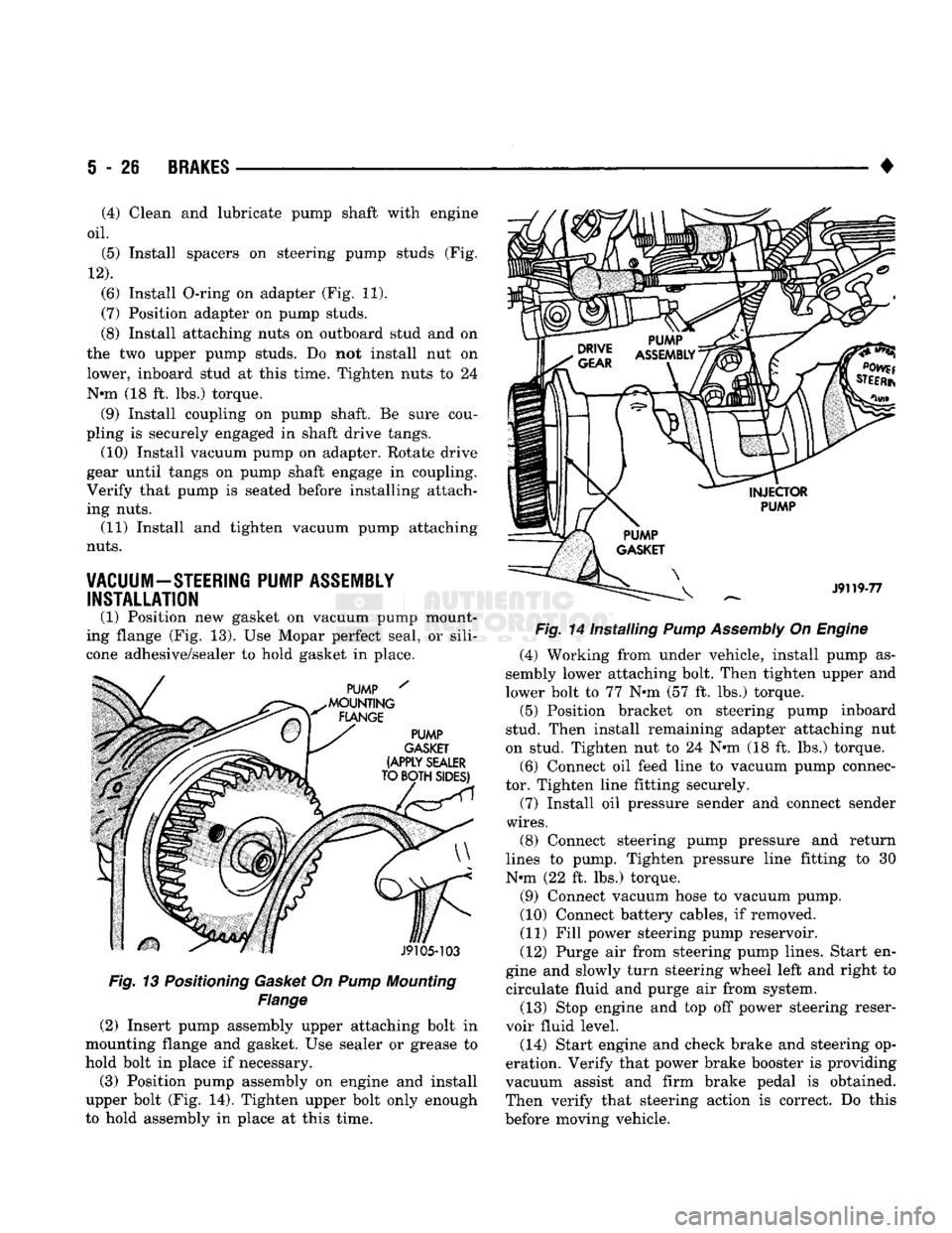
Fig. 13 Positioning Gasket On Pump Mounting
Flange
(2) Insert pump assembly upper attaching bolt in
mounting flange and gasket. Use sealer or grease to
hold bolt in place if necessary.
(3) Position pump assembly on engine and install
upper bolt (Fig. 14). Tighten upper bolt only enough
to hold assembly in place at this time. •
Fig. 14 Installing Pump Assembly On Engine (4) Working from under vehicle, install pump as
sembly lower attaching bolt. Then tighten upper and
lower bolt to 77 N»m (57 ft. lbs.) torque. (5) Position bracket on steering pump inboard
stud. Then install remaining adapter attaching nut
on stud. Tighten nut to 24 N«m (18 ft. lbs.) torque.
(6) Connect oil feed line to vacuum pump connec
tor. Tighten line fitting securely.
(7) Install oil pressure sender and connect sender
wires.
(8) Connect steering pump pressure and return
lines to pump. Tighten pressure line fitting to 30
N-m (22 ft. lbs.) torque.
(9) Connect vacuum hose to vacuum pump.
(10) Connect battery cables, if removed.
(11) Fill power steering pump reservoir.
(12) Purge air from steering pump lines. Start en
gine and slowly turn steering wheel left and right to circulate fluid and purge air from system.
(13) Stop engine and top off power steering reser
voir fluid level.
(14) Start engine and check brake and steering op
eration. Verify that power brake booster is providing
vacuum assist and firm brake pedal is obtained.
Then verify that steering action is correct. Do this
before moving vehicle.
(4) Clean and lubricate pump shaft with engine
oil.
(5) Install spacers on steering pump studs (Fig.
12).
(6) Install O-ring on adapter (Fig. 11).
(7) Position adapter on pump studs.
(8) Install attaching nuts on outboard stud and on
the two upper pump studs. Do not install nut on
lower, inboard stud at this time. Tighten nuts to 24
N-m (18 ft. lbs.) torque. (9) Install coupling on pump shaft. Be sure cou
pling is securely engaged in shaft drive tangs. (10) Install vacuum pump on adapter. Rotate drive
gear until tangs on pump shaft engage in coupling.
Verify that pump is seated before installing attach
ing nuts. (11) Install and tighten vacuum pump attaching
nuts.
VACUUM-STEERING PUMP ASSEMBLY INSTALLATION
(1) Position new gasket on vacuum pump mount
ing flange (Fig. 13). Use Mopar perfect seal, or sili
cone adhesive/sealer to hold gasket in place.
Page 260 of 1502
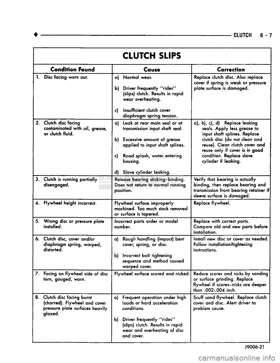
CLUTCH
6 - 7
CLUTCH
SLIPS
Condition
Found
Cause
Correction
1.
Disc
facing
worn
out. a) Normal wear.
b) Driver
frequently
"rides"
(slips)
clutch. Results in rapid
wear overheating.
c) Insufficient clutch cover diaphragm spring tension. Replace clutch
disc.
Also
replace
cover if spring is weak or pressure
plate
surface is damaged.
2. Clutch disc facing contaminated
with
oil, grease,
or clutch fluid. a) Leak at
rear
main seal or at
transmission
input shaft seal.
b) Excessive amount of grease applied to input shaft splines.
c) Road
splash,
water
entering
housing.
d) Slave cylinder leaking. a), b), c), d) Replace leaking
seals.
Apply
less
grease to
input shaft splines. Replace
clutch disc (do not clean and reuse). Clean clutch cover and
reuse only if cover is in good
condition. Replace slave
cylinder if leaking.
3. Clutch is running
partially
disengaged.
Release
bearing sticking-binding.
Does
not
return
to normal running
position.
Verify
that
bearing is actually
binding,
then
replace bearing and
transmission
front
bearing
retainer
if sleeve surface is damaged.
4. Flywheel height incorrect. Flywheel surface improperly
machined. Too much stock removed
or surface is tapered. Replace flywheel.
5. Wrong disc or pressure
plate
installed. Incorrect parts order or model
number. Replace
with
correct parts.
Compare old and new parts before installation.
6. Clutch
disc,
cover and/or diaphragm spring, warped,
distorted. a)
Rough
handling (impact) bent
cover, spring, or
disc.
b) Incorrect bolt tightening sequence and method caused
warped cover. Install new disc or cover as needed.
Follow installation/tightening
instructions.
7. Facing on
flywheel
side of disc torn,
gouged,
worn. Flywheel surface scored and nicked.
Reduce
scores and nicks by sanding
or surface grinding. Replace
flywheel
if scores-nicks are deeper
than
.002-.004
inch.
8. Clutch disc facing burnt (charred). Flywheel and cover
pressure
plate
surfaces heavily
glazed.
a) Frequent operation under high
loads
or hard acceleration
conditions.
b) Driver
frequently
"rides"
(slips)
clutch. Results in rapid
wear and overheating of disc and cover.
Scuff
sand flywheel. Replace clutch
cover and
disc.
Alert driver to problem cause.
J9006-21
Page 273 of 1502
7 - 2
COOLING
SYSTEM
•
NOTE: HEATER
COOLANT FLOW
CIRCUIT
IS
ALWAYS
OPEN
EXCEPT
WHEN
IN MAX. A/C
OR
OFF
MODES
HEATER
INTAKE MANIFOLD
COOLANT FLOW "METERED" FROM REAR
TO
FRONT
AND
BELOW EXHAUST HEAT
CROSSOVER
SHUT
OFF
VALVE
A/C
ONLY COOLANT FLOW
-
PUMP
TO
CYLINDER
BLOCK,
UP
THROUGH
CYLINDER
HEADS
TO
INTAKE MANIFOLD WATER BOX
TO
RADIATOR
—
TO PUMP
•BYPASS
THERMOSTAT CLOSED-HIGH FLOW
THERMOSTAT OPEN
-
LOW FLOW
CYLINDER
HEAD
RR07B52
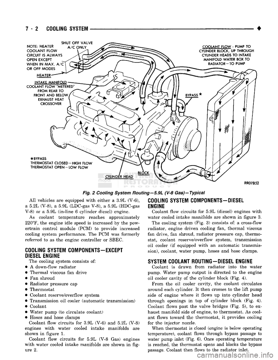
Fig.
2
Cooling
System
Routing—5.9L (V-8 Gas)—Typical All vehicles are equipped with either a 3.9L (V-6),
a 5.2L (V-8), a 5.9L (LDC-gas V-8), a 5.9L (HDC-gas
V-8) or a 5.9L (in-line 6 cylinder diesel) engine.
As coolant temperature reaches approximately
220°F,
the engine idle speed is increased by the pow-
ertrain control module (PCM) to provide increased
cooling system performance. The PCM was formerly
referred to as the engine controller or SBEC.
COOLING
SYSTEM
COMPONENTS—EXCEPT
DIESEL
ENGINE
The cooling system consists of:
• A down-flow radiator
• Thermal viscous fan drive
• Fan shroud
• Radiator pressure cap
• Thermostat
• Coolant reserve/overflow system
• Transmission oil cooler (automatic transmission)
• Coolant
• Water pump (to circulate coolant)
• Hoses and hose clamps Coolant flow circuits for 3.9L (V-6) and 5.2L (V-8)
engines with water cooled intake manifolds are
shown in figure 1. Coolant flow circuits for 5.9L (V-8 Gas) engines
with water cooled intake manifolds are shown in fig ure 2.
COOLING
SYSTEM
COMPONENTS-DIESEL
ENGINE
Coolant flow circuits for 5.9L (diesel) engines with
water cooled intake manifolds are shown in figure 3. The cooling system (Fig. 3) consists of: a cross-flow
radiator, engine driven cooling fan, thermal viscous
fan drive, fan shroud, radiator pressure cap, thermo stat, coolant reserve/overflow system, transmission
oil cooler (if equipped with an automatic transmis
sion),
coolant, water pump, hoses and hose clamps.
SYSTEM
COOLANT ROUTING-DIESEL ENGINE
Coolant is drawn from radiator into the water
pump. Water pump output is directed to the engine oil cooler cavity of the cylinder block (Fig. 4). From the oil cooler cavity, the coolant circulates
around each cylinder. It then crosses to the lift pump
side of engine where it flows up into cylinder head
through openings in top of cylinder block (Fig. 4). Coolant flows past the valve bridges (Fig. 5), to ex
haust manifold side of engine, to thermostat. As cool ant flows toward the thermostat, it provides cooling
for the injector nozzle.
When thermostat is closed (engine is below operating
temperature), coolant flows through bypass passage to
water pump inlet (Fig. 6). Once operating temperature is reached, the thermostat opens and blocks the bypass
passage. Coolant then flows to the radiator inlet.
Page 276 of 1502
•
COOLING
SYSTEM
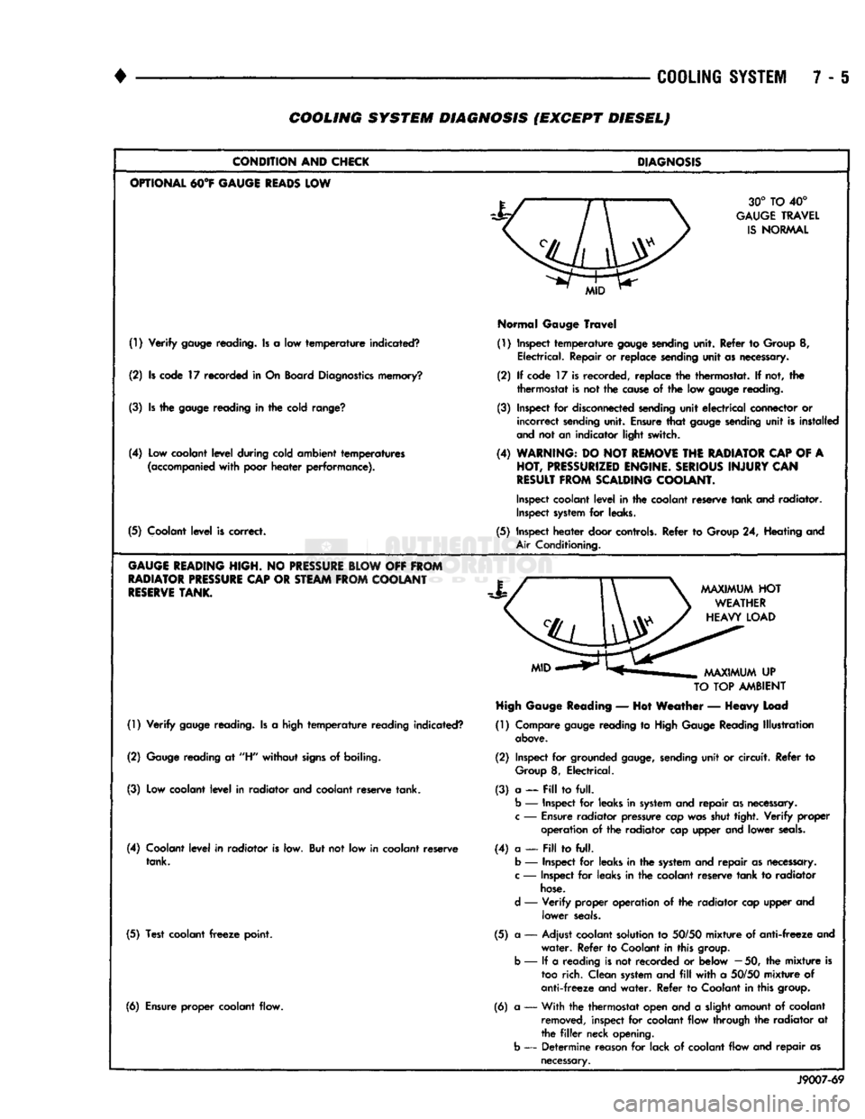
7 - 6 COOLING SYSTEM DIAGNOSIS (EXCEPT DIESEL)
CONDITION
AND
CHICK
OPTIONAL
M°¥
GAUGE
READS
LOW
(!) Verify
gauge
reading. Is a low temperature indicated?
(2) Is code 17 recorded in On Board
Diagnostics
memory?
(3) Is the
gauge
reading in the cold
range?
(4) Low coolant level during cold ambient temperatures
(accompanied
with poor heater performance).
(5) Coolant level is correct.
GAUGE
HEADING
HIGH.
NO
PRESSURE
BLOW
OFF
FROM
RADIATOR
PRESSURE
CAP
OR
STEAM
FROM
COOLANT
RESERVE
TANK.
(1) Verify
gauge
reading. Is a high temperature reading indicated?
(2)
Gauge
reading at
"H"
without
signs
of boiling.
(3) Low coolant level in radiator and coolant reserve tank.
(4) Coolant level in radiator is low. But not low in coolant reserve tank.
(5) Test coolant
freeze
point.
(6) Ensure proper coolant flow.
DIAGNOSIS
30° TO 40°
GAUGE
TRAVEL
IS
NORMAL
Normal
Gauge
Travel
(1) Inspect temperature
gauge
sending
unit. Refer to Group 8, Electrical. Repair or replace sending unit as necessary.
(2) If code 17 is recorded, replace the thermostat. If not, the thermostat is not the
cause
of the low
gauge
reading.
(3) Inspect for
disconnected
sending
unit electrical connector or incorrect
sending
unit. Ensure that
gauge
sending
unit is installed
and
not an indicator light switch.
(4)
WARNING:
DO NOT
REMOVE
THE
RADIATOR
CAP
OF A
HOT,
PRESSURIZED
ENGINE.
SERIOUS
INJURY
CAN
RESULT
FROM
SCALDING
COOLANT.
Inspect
coolant level in the coolant reserve tank and radiator.
Inspect
system
for leaks.
(5) Inspect heater door
controls.
Refer to Group 24, Heating and
Air
Conditioning.
TO
TOP
AMBIENT
High
Gauge
Reading
— Hot Weather — Heavy Load
(1) Compare
gauge
reading to
High
Gauge
Reading Illustration
above.
(2) Inspect for grounded
gauge,
sending
unit or circuit. Refer to
Group
8, Electrical.
(3) a — Pill to full.
b
— Inspect for leaks in
system
and repair as
necessary,
c
—
Ensure
radiator pressure cap was shut tight. Verify
proper
operation of the radiator cap upper and lower
seals.
(4) a —
Fill
to full,
b
— Inspect for leaks in the
system
and repair as
necessary,
c
— Inspect for leaks in the coolant reserve tank to radiator
hose.
d
— Verify proper operation of the radiator cap upper and lower
seals.
(5) a — Adjust coolant solution to
50/50
mixture of anti-freeze and water. Refer to Coolant in this
group,
b
— If a reading is not recorded or below
—
50, the mixture is
too
rich. Clean
system
and
fill
with a
50/50
mixture of
anti-freeze and water. Refer to Coolant in this
group.
(6) a •— With the thermostat open and a slight amount of coolant
removed,
inspect for coolant flow through the radiator at
the
filler
neck opening,
b
— Determine reason for lack of coolant flow and repair as
necessary.
J9007-69
Page 281 of 1502
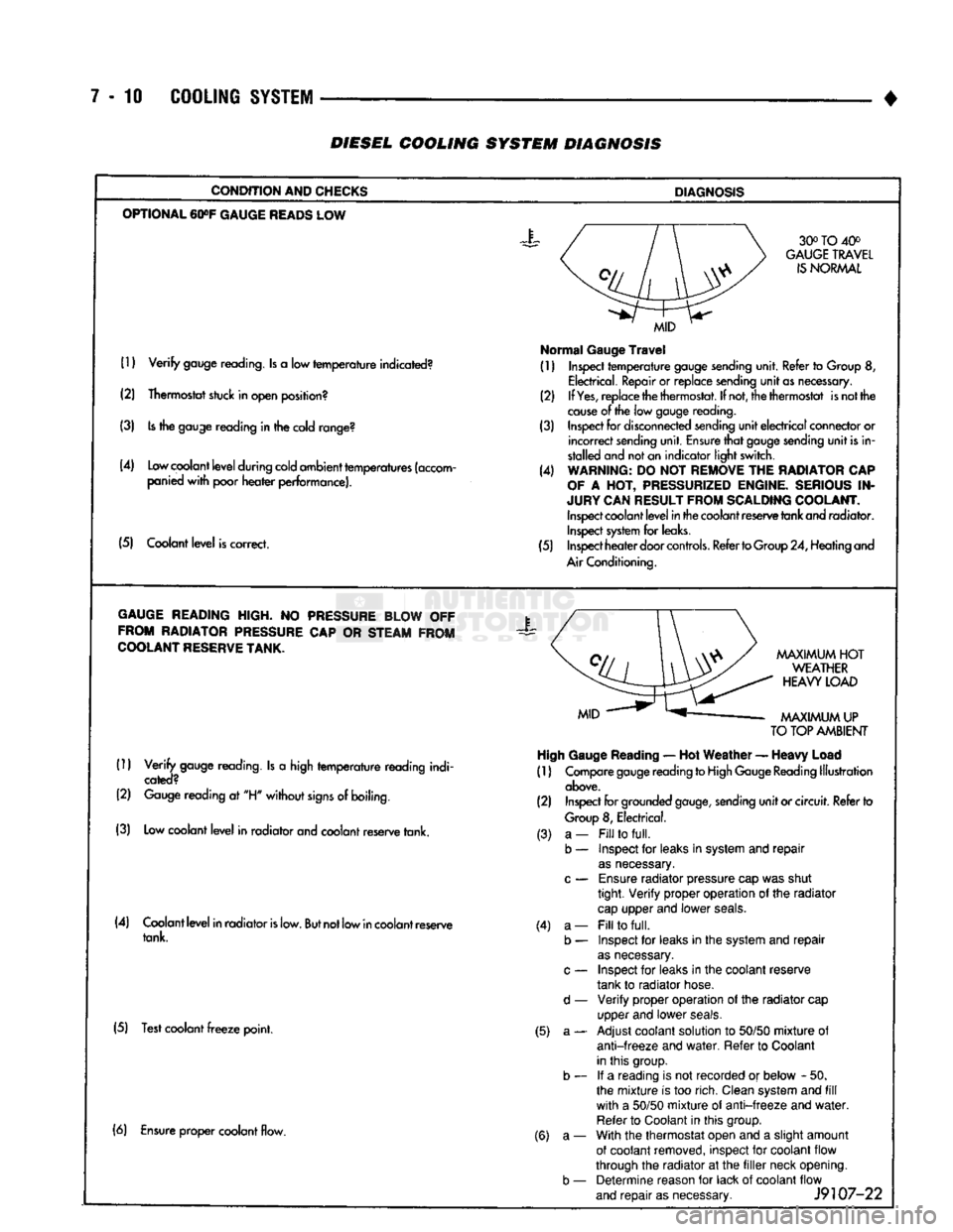
7-10 COOLING SYSTEM
•
DIESEL
COOLING SYSTEM
DIAGNOSIS
CONDITION AND CHECKS
DIAGNOSIS
OPTIONAL
60»F
GAUGE
READS
LOW 30° TO 40°
GAUGE
TRAVEL
IS
NORMAL
(1)
Verify
gauge reading. Is a low
temperature
indicated?
(2) Thermostat stuck in open position?
(3) Is the gauge reading in the cold range?
(4) Low coolant
level
during cold ambient temperatures (accom panied
with
poor
heater
performance).
(5) Coolant
level
is correct.
MID
Normal
Gauge
Travel
(1) Inspect
temperature
gauge sending unit. Refer to Group 8,
Electrical. Repair or replace sending
unit
as necessary.
(2) If
Yes,
replace the thermostat. If not, the thermostat is not the
cause
of the low gauge
reading.
(3) Inspect for disconnected sending
unit
electrical
connector or
incorrect
sending unit. Ensure
that
gauge sending
unit
is in
stalled and not an indicator light switch.
(4) WARNING: DO NOT REMOVE THE RADIATOR CAP
OF
A HOT, PRESSURIZED ENGINE. SERIOUS IN
JURY CAN RESULT FROM SCALDING COOLANT. Inspect coolant
level
in the coolant reserve tank and radiator. Inspect system for leaks.
(5) Inspect
heater
door
controls.
Refer to Group 24, Heating and
Air Conditioning.
GAUGE
READING HIGH. NO PRESSURE BLOW OFF FROM RADIATOR PRESSURE CAP OR STEAM FROM
COOLANT
RESERVE
TANK.
X
(1)
Verify
gauge reading. Is a high
temperature
reading indi
cated?
(2) Gauge reading at "H"
without
signs
of boiling.
(3) Low coolant
level
in radiator and coolant reserve tank.
MAXIMUM
HOT
WEATHER
HEAVY
LOAD
MAXIMUM
UP
TO
TOP AMBIENT High Gauge
Reading
— Hot
Weather
—
Heavy
Load
(1) Compare gauge reading to High Gauge Reading Illustration
above.
(2) Inspect for grounded
gauge,
sending
unit
or circuit. Refer to
Group
8, Electrical.
(4) Coolant
level
in radiator
is
low.
But
not low in coolant reserve tank.
(5) Test coolant
freeze
point. (3) a-
b — (4) a-
b —
d —
(5) a- (6) Ensure proper coolant flow.
(6) a-
b —
Fill
to
full.
Inspect for leaks in system and
repair
as
necessary.
Ensure
radiator pressure cap was shut
tight.
Verify
proper operation of the radiator
cap
upper and lower
seals.
Fill
to
full.
Inspect for leaks in the system and
repair
as
necessary.
Inspect for leaks in the coolant reserve
tank to radiator hose.
Verify
proper operation of the radiator cap
upper and lower
seals.
Adjust coolant solution to
50/50
mixture
of
anti-freeze
and
water.
Refer to Coolant
in this group. If a reading is not recorded or below - 50.
the
mixture
is too rich. Clean system and
fill
with
a
50/50
mixture
of
anti-freeze
and
water.
Refer to Coolant in this group.
With the thermostat open and a slight amount
of coolant removed, inspect for coolant flow
through the radiator at the
filler
neck opening. Determine reason for lack of coolant flow
and
repair
as necessary.
J9107-22
Page 283 of 1502
7
- 12
COOLING
SYSTEM
• DIESEL COOLING SYSTEM DIAGNOSIS-CONTINUED
CONDITION
AND
CHECKS
DIAGNOSIS
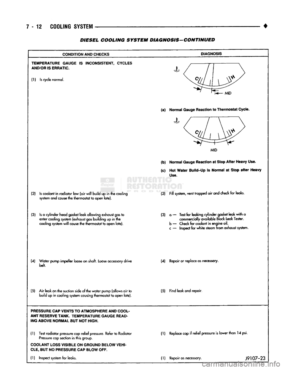
TEMPERATURE GAUGE
IS
INCONSISTENT,
CYCLES
AND/OR
IS
ERRATIC.
J
(1)
Is
cycle
normal.
(a)
Normal
Gauge
Reaction
to Thermostat
Cycle.
Normal
Gauge
Reaction
to Thermostat
Cycle.
MID
(b)
Normal
Gauge
Reaction
at
Stop
After
Heavy
Use.
(c)
Hot
Water
Build-Up
Is
Normal
at
Stop
after
Heavy
Use.
(2)
Is
coolant
in
radiator
low
(air
will
build
up in
the
cooling
system and cause
the
thermostat
to
open
late). (2)
Fill
system,
vent
trapped
air
and
check
for
leaks.
(3)
Is
a
cylinder
head
gasket
leak
allowing
exhaust
gas
to
enter
cooling
system
(exhaust
gas
building
up in
the
cooling
system
will
cause
the
thermostat
to
open
late).
(3)
a
—
Test
for
leaking
cylinder
gasket
leak
with
a
commercially
available
Block
Leak
Tester,
b
—
Check
for
coolant
in
enaine
oil.
c
—
Inspect
for
white
steam
from
exhaust
system.
(4)
Water
pump
impeller
loose
on
shaft.
Loose
accessory
drive
belt. (4)
Repair or
replace
as
necessary.
(5)
Air
leak
on
the
suction
side
of the
water
pump
(allows
air
to
build
up in
cooling
system causing
thermostat
to
open
late). (5)
Find
leak
and
repair.
PRESSURE
CAP
VENTS
TO
ATMOSPHERE
AND
COOL
ANT
RESERVE
TANK.
TEMPERATURE GAUGE
READ
ING ABOVE NORMAL
BUT NOT
HIGH.
(1)
Test
radiator
pressure
cap
relief
pressure.
Refer
to
Radiator
Pressure
cap
section
in
this
group.
ID
Replace
cap
if relief
pressure
is
lower
than
14
psi.
COOLANT
LOSS
VISIBLE
ON
GROUND BELOW VEHI
CLE,
BUT NO
PRESSURE
CAP
BLOW
OFF.
(1)
Inspect
system
for
leaks.
(1)
Repair
as
necessary.
J9107-23
Page 286 of 1502
•
COOLING SYSTEM
7 - 15
SERVICE
PROCEDURES
INDEX
page
Coolant
26
Coolant Reserve/Overflow System
30
Cooling System Cleaning/Reverse Flushing
28
Cooling System Fan—Diesel Engine
. 37
Cooling System
Fan—Gas
Engines
36
Cooling System
Hoses
34
Draining Cooling System
27
Pressure
Testing
Radiator
Caps
............. 32
Radiator Pressure
Cap 31
Radiators
32
Refilling
the
Cooling System
28
WATER PUMPS—EXCEPT DIESEL
A centrifugal water pump circulates coolant
through the water jackets, passages, intake manifold,
radiator core, cooling system hoses and heater core.
The pump is driven from the engine crankshaft by a drive belt. The water pump impeller is pressed onto the rear
of a shaft that rotates in a bearing pressed into the
water pump body. The body has a small hole for ven
tilation. The water pump seals are lubricated by an
tifreeze in the coolant mixture. Additional lubrication is not necessary. A quick test to determine if pump is working is to
check if heater warms properly. A defective water
pump will not be able to circulate heated coolant
through the long heater hose to the heater core. The water pump on all models can be removed
without discharging the air conditioning system (if equipped).
REMOVAL The water pump on all gas powered engines is
bolted directly to the engine timing chain case/cover.
A gasket is used as a seal between the water pump
and timing chain case/cover.
If water pump is replaced because of bearing/shaft
damage or leaking shaft seal, the mechanical cooling
fan assembly should also be inspected. Inspect for fa tigue cracks, loose blades or loose rivets that could
have resulted from excessive vibration. Replace fan if any of these conditions are found. Also check condi
tion of the thermal viscous fan drive. Refer to Vis
cous Fan Drive in this group. (1) Disconnect negative battery cable from battery.
(2) Drain cooling system. Refer to Draining Cool
ing System in this group. Do not waste reusable coolant. If solution is clean,
drain coolant into a clean container for reuse.
(3)
Disconnect throttle cable from clip at top of fan
shroud.
page
Testing
Cooling System
for
Leaks
. 29
Thermostat
22
Transmission
Oil
Cooler—Diesel
35
Transmission
Oil
Cooler—Except Diesel
35
Transmission Oil-To-Air Cooler
36
Viscous
Fan
Drive
38
Water
Pump
Bypass
Hose—All
Gas
Powered
Engines
.............................. 19
Water
Pumps—5.9L Diesel
18
Water
Pumps—Except Diesel
15
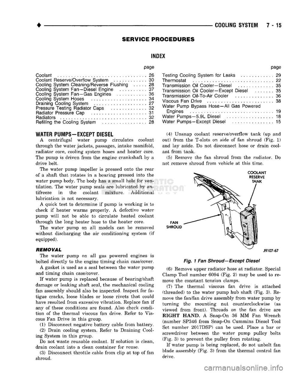
(4) Unsnap coolant reserve/overflow tank (up and
out) from the T-slots on side of fan shroud (Fig. 1) and lay aside. Do not disconnect hose or drain cool
ant from tank.
(5) Remove the fan shroud from the radiator. Do
not remove shroud from vehicle at this time.
FAN
SHROUD
J9107-67
Fig.
1 Fan
Shroud—Except
Diesel
(6) Remove upper radiator hose at radiator. Special
Clamp Tool number 6094 (Fig. 2) may be used to re
move the constant tension clamps.
(7) The thermal viscous fan drive is attached
(threaded) to the water pump hub shaft (Fig. 3). Re
move the fan/fan drive assembly from water pump by
turning the mounting nut counterclockwise (as viewed from front). Threads on the fan drive are RIGHT HAND. A Snap-On 36 MM Fan Wrench (number SP346 from Snap-On Cummins Diesel Tool
Set number 2017DSP) can be used. Place a bar or
screwdriver between the water pump pulley bolts (Fig. 3) to prevent the pulley from rotating.
If water pump is being replaced, do not unbolt fan
blade assembly (Fig. 3) from the thermal control fan drive.
Page 298 of 1502
•
COOLING
SYSTEM
7 - 27 down to -67.7°C (-90°F). A higher percentage will
freeze at a warmer temperature. Also, a higher per centage of antifreeze can cause the engine to over
heat because specific heat of antifreeze is lower than
that of water.
CAUTION:
Richer
antifreeze
mixtures
cannot
be
measured
with
normal
field
equipment
and can
cause
problems
associated
with 100
percent
ethyl
ene-glycol.
COOLANT SELECTION-ADDITIVES The presence of aluminum components in the cool
ing system requires strict corrosion protection. Main
tain coolant at specified level with a mixture of ethylene-glycol based antifreeze and water. Only use an antifreeze containing ALUGARD 340-2
™
such as
Mopar Antifreeze. If coolant becomes contaminated
or looses color, drain and flush cooling system and
fill with correctly mixed solution.
A 0.25 percent emulsifiable oil is added to the ra
diator at the factory to prevent solder corrosion.
CAUTION:
Do not use
coolant
additives
that are
claimed
to
improve
engine
cooling.
COOLANT SERVICE-EXCEPT DIESEL It is recommended that the cooling system be
drained and flushed at 84,000 kilometers (52,500
miles) or 3 years, whichever occurs first. Then every
two years or 48,000 kilometers (30,000 miles), which ever occurs first.
COOLANT SERVICE-DIESEL ENGINE It is recommended that the cooling system be
drained and flushed every 24 months or 38,600 kilo meters (24,000 miles), whichever occurs first.
COOLANT LEVEL CHECK-ROUTINE Do not remove radiator cap for routine coolant
level inspections. The coolant level can be checked at the coolant reserve/overflow tank.
The coolant reserve/overflow system provides a
quick visual method for determining the coolant
level without removing the radiator pressure cap.
With engine idling and at normal operating temper ature, observe coolant level in coolant reserve/over
flow tank. The coolant level should be between the MIN and MAX (diesel engine) or ADD and FULL (gas engines) marks.
ADDING ADDITIONAL COOLANT-ROUTINE Do not remove the radiator cap to add coolant
to the system. When adding coolant to maintain the correct level, do so at the coolant reserve/overflow
tank with a 50/50 mixture of ethylene-glycol anti
freeze (containing Alugard 340-2 ™) and water. Re move the radiator cap only for testing or when
refilling the system after service. Removing cap un necessarily can cause loss of coolant and allow air to
enter system. This produces corrosion.
COOLANT LEVEL CHECK-SERVICE The cooling system is closed and designed to main
tain coolant level to the top of the radiator.
WARNING:
DO
NOT OPEN RADIATOR DRAINCOCK
WITH
ENGINE RUNNING
OR
WHILE ENGINE
IS HOT
AND COOLING
SYSTEM
IS
UNDER
PRESSURE.
When vehicle servicing requires a coolant level
check in the radiator, drain several ounces of coolant
from the radiator drain cock. Do this while observing
the coolant reserve/overflow system tank. The cool ant level in the reserve/overflow tank should drop
slightly. If not, inspect for a leak between radiator and coolant reserve/overflow system connection. Re
move radiator cap. The coolant level should be to the
top of the radiator. If not and if coolant level in re serve/overflow tank is at the ADD (gas engines) or
MIN (5.9L diesel engine) mark, check for:
• An air leak in the coolant reserve/overflow tank
• An air leak in the radiator filler neck
• Leak in the pressure cap seal to the radiator filler
neck
LOW COOLANT LEVEL-AERATION If the coolant level in the radiator drops below the
top of the radiator core tubes, air will enter the sys
tem. Low coolant level can cause the thermostat pellet
to be suspended in air instead of coolant. This will cause the thermostat to open later, which in turn causes higher coolant temperature. Air trapped in
cooling system also reduces the amount of coolant
circulating in the heater core. This may result in low
heat output.
DEAERATION As the engine operates, air trapped in the cooling
system gathers under the radiator cap. The next time
engine is operated, thermal expansion of coolant will
push trapped air past radiator cap into coolant re serve/overflow tank. Here it escapes to atmosphere in
the tank. When engine cools down the coolant, it will
be drawn from reserve/overflow tank into radiator to replace removed air.
DRAINING
COOLING
SYSTEM
WARNING:
DO NOT
REMOVE
THE
CYLINDER BLOCK DRAIN PLUGS
OR
LOOSEN THE RADIATOR
DRAIN PLUG
WITH
SYSTEM
HOT AND
UNDER
PRESSURE.
SERIOUS BURNS
FROM
COOLANT
CAN OCCUR.
Page 299 of 1502
7 - 28
COOLING SYSTEM
DO NOT WASTE reusable coolant. If the solution
is clean, drain the coolant into a clean container for
reuse.
(1) Start the engine and place the heater control
temperature selector in the Full On position. Engine vacuum is needed to actuate the heater controls.
(2) Turn the ignition off. (3) Do not remove radiator cap when draining cool
ant from reserve/overflow tank. Open radiator drain
plug and when tank is empty, remove radiator cap. If
the coolant reserve/overflow tank does not drain, re fer to the Testing Cooling System for Leaks section
in this group. The coolant need not be removed from
tank unless the system is being refilled with fresh mixture.
(4) On vehicles equipped with gas powered en
gines,
remove the cylinder block drain plugs. These are located on the sides of the block towards the
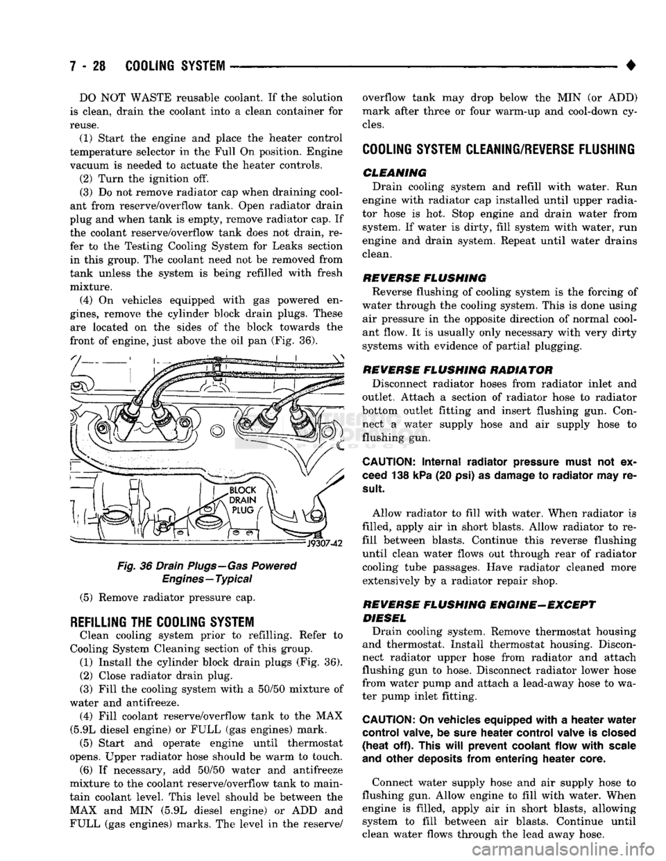
front of engine, just above the oil pan (Fig. 36).
Fig.
36 Drain Plugs—Gas Powered
Engines—Typical
(5) Remove radiator pressure cap.
REFILLING
THE
COOLING SYSTEM
Clean cooling system prior to refilling. Refer to
Cooling System Cleaning section of this group. (1) Install the cylinder block drain plugs (Fig. 36).
(2)
Close radiator drain plug.
(3) Fill the cooling system with a 50/50 mixture of
water and antifreeze. (4) Fill coolant reserve/overflow tank to the MAX
(5.9L diesel engine) or FULL (gas engines) mark. (5) Start and operate engine until thermostat
opens. Upper radiator hose should be warm to touch. (6) If necessary, add 50/50 water and antifreeze
mixture to the coolant reserve/overflow tank to main
tain coolant level. This level should be between the MAX and MIN (5.9L diesel engine) or ADD and FULL (gas engines) marks. The level in the reserve/ overflow tank may drop below the MIN (or ADD)
mark after three or four warm-up and cool-down cy
cles.
COOLING SYSTEM CLEANING/REVERSE FLUSHING
CLEMMING Drain cooling system and refill with water. Run
engine with radiator cap installed until upper radia
tor hose is hot. Stop engine and drain water from system. If water is dirty, fill system with water, run
engine and drain system. Repeat until water drains
clean.
REVERSE
FLUSHING
Reverse flushing of cooling system is the forcing of
water through the cooling system. This is done using air pressure in the opposite direction of normal cool
ant flow. It is usually only necessary with very dirty
systems with evidence of partial plugging.
REVERSE
FLUSHING
RADIATOR Disconnect radiator hoses from radiator inlet and
outlet. Attach a section of radiator hose to radiator
bottom outlet fitting and insert flushing gun. Con
nect a water supply hose and air supply hose to flushing gun.
CAUTION:
Internal
radiator
pressure must
not'ex
ceed 138 kPa (20 psi) as damage to
radiator
may re
sult
Allow radiator to fill with water. When radiator is
filled, apply air in short blasts. Allow radiator to re
fill between blasts. Continue this reverse flushing
until clean water flows out through rear of radiator cooling tube passages. Have radiator cleaned more extensively by a radiator repair shop.
REVERSE
FLUSHING
ENGINE-EXCEPT DIESEL Drain cooling system. Remove thermostat housing
and thermostat. Install thermostat housing. Discon
nect radiator upper hose from radiator and attach
flushing gun to hose. Disconnect radiator lower hose
from water pump and attach a lead-away hose to wa
ter pump inlet fitting.
CAUTION;
On vehicles equipped
with
a
heater
water
control
valve, be sure
heater
control
valve is closed
(heat
off). This
will
prevent
coolant
flow
with
scale
and
other
deposits
from
entering
heater
core.
Connect water supply hose and air supply hose to
flushing gun. Allow engine to fill with water. When engine is filled, apply air in short blasts, allowing system to fill between air blasts. Continue until
clean water flows through the lead away hose.
Page 301 of 1502
7 - 30
COOLING
SYSTEM
•
COOLING
SYSTEM
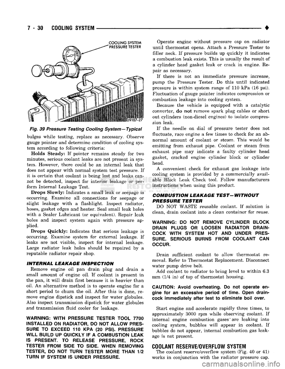
Fig.
39
Pressure
Testing
Cooling
System—Typical bulges while testing, replace as necessary. Observe
gauge pointer and determine condition of cooling sys
tem according to following criteria:
Holds Steady: If pointer remains steady for two
minutes, serious coolant leaks are not present in sys
tem. However, there could be an internal leak that does not appear with normal system test pressure. If
it is certain that coolant is being lost and leaks can
not be detected, inspect for interior leakage or per
form Internal Leakage Test.
Drops Slowly: Indicates a small leak or seepage is
occurring. Examine all connections for seepage or
slight leakage with a flashlight. Inspect radiator,
hoses,
gasket edges and heater. Seal small leak holes
with a Sealer Lubricant (or equivalent). Repair leak
holes and inspect system again with pressure ap
plied.
Drops Quickly: Indicates that serious leakage is
occurring. Examine system for external leakage. If
leaks are not visible, inspect for internal leakage.
Large radiator leak holes should be repaired by a
reputable radiator repair shop.
INTERNAL LEAKAGE INSPECTION Remove engine oil pan drain plug and drain a
small amount of engine oil. If coolant is present in
the pan, it will drain first because it is heavier than
oil.
An alternative method is to operate engine for a
short period to churn the oil. After this is done, re
move engine dipstick and inspect for water globules.
Also inspect transmission dipstick for water globules and transmission fluid cooler for leakage.
WARNING:
WITH
PRESSURE TESTER TOOL
7700
INSTALLED
ON
RADIATOR,
DO
NOT ALLOW
PRES
SURE
TO
EXCEED
110 KPA (20
PSI). PRESSURE
WILL
BUILD
UP
QUICKLY
IF A
COMBUSTION LEAK
IS
PRESENT.
TO
RELEASE
PRESSURE,
ROCK
TESTER
FROM SIDE
TO
SIDE. WHEN REMOVING
TESTER,
DO NOT
TURN TESTER MORE THAN
1/2
TURN
IF
SYSTEM
IS
UNDER
PRESSURE.
Operate engine without pressure cap on radiator
until thermostat opens. Attach a Pressure Tester to
filler neck. If pressure builds up quickly it indicates a combustion leak exists. This is usually the result of
a cylinder head gasket leak or crack in engine. Re
pair as necessary.
If there is not an immediate pressure increase,
pump the Pressure Tester. Do this until indicated
pressure is within system range of 110 kPa (16 psi). Fluctuation of gauge pointer indicates compression or
combustion leakage into cooling system.
Because the vehicle is equipped with a catalytic
converter, do not remove spark plug cables or short
out cylinders (non-diesel engines) to isolate compres
sion leak.
If the needle on dial of pressure tester does not
fluctuate, race engine a few times to check for an ab normal amount of coolant or steam. This would be
emitting from exhaust pipe. Coolant or steam from
exhaust pipe may indicate a faulty cylinder head
gasket, cracked engine cylinder block or cylinder
head. A convenient check for exhaust gas leakage into
cooling system is provided by a commercially avail able Block Leak Check tool. Follow manufacturers
instructions when using this product.
COMBUSTION LEAKAGE TEST-WITHOUT
PRESSURE TESTER DO NOT WASTE reusable coolant. If solution is
clean, drain coolant into a clean container for reuse.
WARNING:
DO NOT
REMOVE CYLINDER BLOCK DRAIN PLUGS
OR
LOOSEN RADIATOR DRAIN-
COCK
WITH
SYSTEM
HOT AND
UNDER PRES
SURE.
SERIOUS BURNS FROM COOLANT
CAN
OCCUR.
Drain sufficient coolant to allow thermostat re
moval. Refer to Thermostat Replacement. Disconnect
water pump drive belt. Add coolant to radiator to bring level to within 6.3
mm (1/4 in) of top of thermostat housing.
CAUTION:
Avoid
overheating.
Do not
operate
en
gine
for an
excessive
period
of
time.
Open
drain-
cock
immediately
after
test
to
eliminate
boil
over.
Start engine and accelerate rapidly three times, to
approximately 3000 rpm while observing coolant. If
internal engine combustion gases% are leaking into
cooling system, bubbles will appear in coolant. If
bubbles do not appear, internal combustion gas leak age is not present.
COOLANT
RESERVE/0WERFL0W
SYSTEM
The coolant reserve/overflow system (Fig. 40 or 41)
works in conjunction with the radiator pressure cap.