oil capacity DODGE TRUCK 1993 Service User Guide
[x] Cancel search | Manufacturer: DODGE, Model Year: 1993, Model line: TRUCK, Model: DODGE TRUCK 1993Pages: 1502, PDF Size: 80.97 MB
Page 751 of 1502
9
- 148 5.9L
(DIESEL) ENGINE
• Make sure the idler gear pin is installed in the lo
cating bore in the cylinder block. (2) Install the pump. Tighten the oil pump mount
ing bolts in two steps and in the sequence shown (Fig. 2).
• Step
1—Tighten
to 5 N«m (44 in. lbs.) torque.
• Step 2-Tighten to 24 N*m (18 ft. lbs.) torque. (3) The back plate on the pump seats against the
bottom of the bore in the cylinder block. When the
pump is correctly installed, the flange on the pump will not touch the cylinder block.
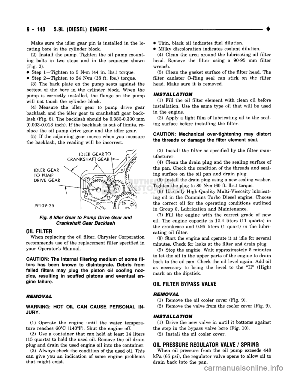
(4) Measure the idler gear to pump drive gear
backlash and the idler gear to crankshaft gear back lash (Fig. 8). The backlash should be 0.080-0.330 mm (0.003-0.013 inch). If the backlash is out of limits, re
place the oil pump drive gear and the idler gear.
(5) If the adjoining gear moves when you measure
the backlash, the reading will be incorrect.
Fig.
8
idler
Gear to
Pump
Drive Gear and Crankshaft Gear
Backlash
OIL FILTER
When replacing the oil filter, Chrysler Corporation
recommends use of the replacement filter specified in
your Operator's Manual.
CAUTION:
The
internal filtering medium
of
some
fil
ters
has
been known
to
disintegrate. Debris from
failed filters
may
plug
the
piston
oil
cooling noz
zles,
resulting
in
scuffed pistons
and
eventual
en
gine
failure.
REMOVAL
WARNING:
HOT OIL CAN
CAUSE PERSONAL
IN
JURY.
(1) Operate the engine until the water tempera
ture reaches 60°C (140°F). Shut the engine off.
(2) Use a container that can hold at least 14 liters
(15 quarts) to hold the used oil. Remove the oil drain
plug and drain the used engine oil into the container.
(3) Always check the condition of the used oil. This
can give you an indication of some engine problems
that might exist. • Thin, black oil indicates fuel dilution.
• Milky discoloration indicates coolant dilution.
(4) Clean the area around the lubricating oil filter
head. Remove the filter using a 90-95 mm filter
wrench.
(5) Clean the gasket surface of the filter head. The
filter canister O-Ring seal can stick on the filter
head. Make sure it is removed.
INSTALLATION (1) Fill the oil filter element with clean oil before
installation. Use the same type oil that will be used
in the engine.
(2) Apply a light film of lubricating oil to the seal
ing surface before installing the filter.
CAUTION:
Mechanical over-tightening
may
distort
the threads
or
damage
the filter
element seal.
(3) Install the filter as specified by the filter man
ufacturer. (4) Clean the drain plug and the sealing surface of
the pan. Check the condition of the threads and seal ing surface on the oil pan and drain plug.
(5) Install the drain plug using a new sealing washer.
Tighten the plug to 80 N-m (60 ft. lbs.) torque.
(6) Use only High-Quality Multi-Viscosity lubricat
ing oil in the Cummins Turbo Diesel engine. Choose
the correct oil for the operating conditions outlined in Group 0, Lubrication and Maintenance.
(7) Fill the enginfe with the correct grade of new
oil.
The engine capacity is i0.4 liters (11 quarts) in
the crankcase and 0.95 liters (1 quart) in the lubri cating oil filter. (8) Start the engine and operate it at idle for several
minutes. Check for leaks at the filter and drain plug.
(9) Stop the engine. Wait approximately 5 minutes
to let the oil in the upper parts of the engine to drain
back to the oil pan. Check the oil level again. Add oil as necessary to bring the level to the "H" (High)
mark on the dipstick.
OIL FILTER
BYPASS
VALWE
REMOVAL
(1) Remove the oil cooler cover (Fig. 9). (2) Remove the valve from the cooler cover (Fig. 9).
INSTALLATION (1) Drive the new valve in until it bottoms against
the step in the bypass valve bore (Fig. 10).
(2) Install the oil cooler cover.
OIL PRESSURE REGULATOR VALVE
/
SPRING
When oil pressure from the oil pump exceeds 448
kPa (65 psi), the regulator valve opens to allow oil to
drain back into the pan.
Page 806 of 1502
•
FRAME
AND
BUMPERS
13 - 19
SNOW
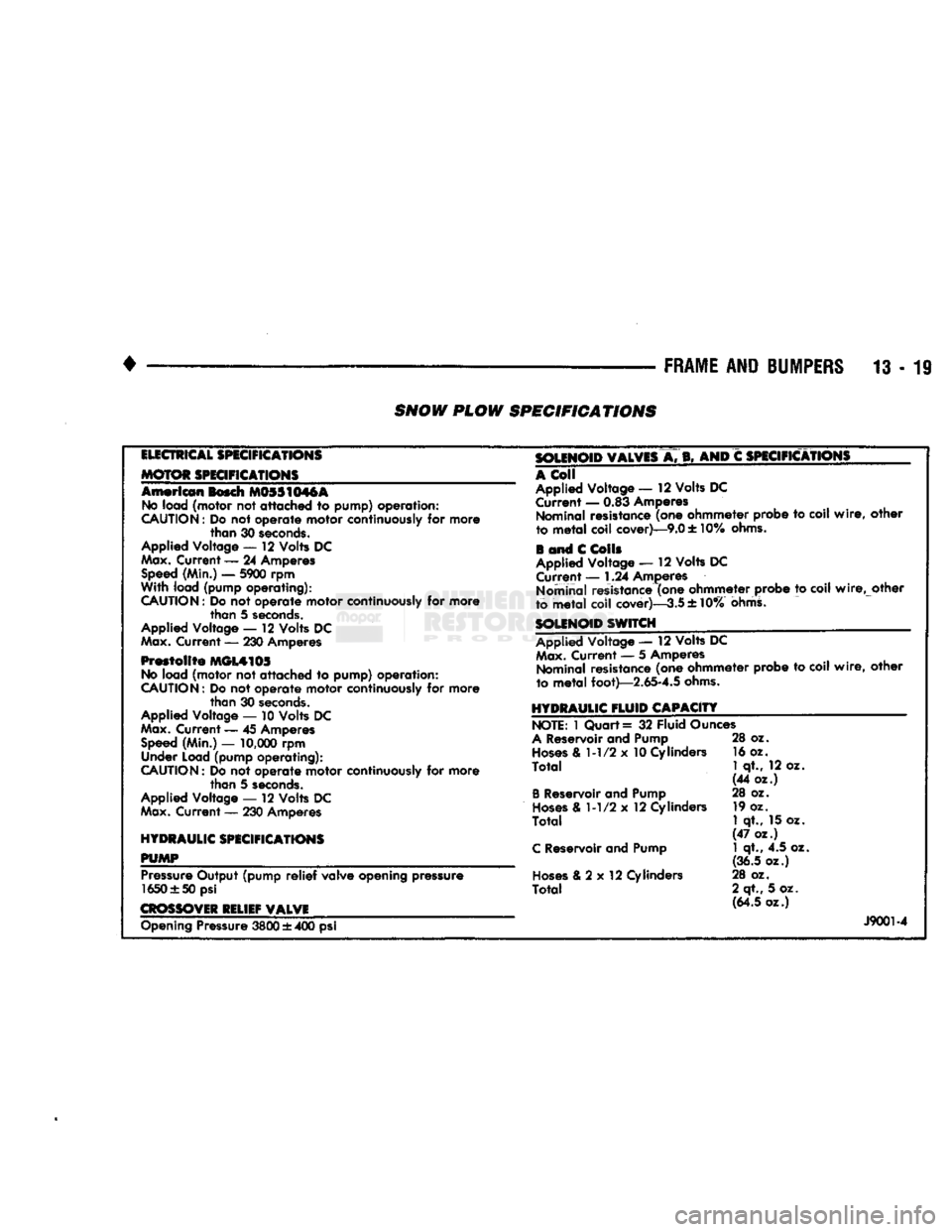
PLOW SPECIFICATIONS
ELECTRICAL
SPECIFICATIONS
MOTOR SPECIFICATIONS
American
Bosch M0SS1M6A No
load
(motor
not
attached to pump) operation:
CAUTION:
Do not
operate
motor
continuously
for
more
than
30
seconds.
Applied Voltage
— 12
Volts
DC
Max. Current — 24
Amperes Speed
(Min.) —
5900
rpm
With
load
(pump operating):
CAUTION:
Do
not
operate motor
continuously
for more than 5
seconds.
Applied Voltage — 12 Volts DC
Max.
Current — 230 Amperes
Prestolite MGL4105
No
load (motor not attached to pump) operation:
CAUTION:
Do not operate motor continuously for more than 30
seconds.
Applied Voltage — 10 Volts DC
Max.
Current — 45 Amperes
Speed
(Min.) —
10,000
rpm Under Load (pump operating):
CAUTION:
Do not operate motor continuously for more than 5
seconds.
Applied Voltage —- 12 Volts DC
Max.
Current — 230 Amperes
HYDRAULIC SPECIFICATIONS
PUMP
m
Pressure
Output (pump
relief
valve opening pressure 1650 ±50 psi
CROSSOVER
RELIEF VALVE SOLENOID VALVES
A. B, AND C
SPECIFICATIONS
A
Coll
Applied Voltage — 12 Volts DC Current — 0.83 Amperes Nominal resistance (one ohmmeter probe to coil
wire,
other
to
metal
coil cover)—9.0 ± 10%
ohms.
i and C
Colls
Applied Voltage — 12 Volts DC Current — 1.24 Amperes
Nominal resistance (one ohmmeter probe to coil
wire,
other
to metaT coil cover)—-3.5 ± 10%
ohms.
SOLENOID SWITCH
Applied Voltage — 12 Volts
DC Max.
Current — 5 Amperes Nominal resistance (one ohmmeter probe to coil
wire,
other
to
metal
foot)—2.65-4.5
ohms.
HYDRAULIC
FLUID
CAPACITY NOTE:
1 Quart = 32 Fluid Ounces
A
Reservoir and Pump
Hoses
& 1-1/2 x 10 Cylinders
Total
B
Reservoir and Pump
Hoses
& 1-1/2 x 12 Cylinders
Total
C
Reservoir and Pump
Hoses
& 2 x 12 Cylinders
Total
28 oz.
16 oz.
1
qt., 12 oz.
(44 oz.)
28 oz. 19 oz.
1
qt., 15 oz.
(47 oz.) 1 qt., 4.5 oz.
(36.5 oz.)
28 oz.
2 qt., 5 oz. (64.5 oz.) Opening Pressure
3800
± 400 psi
J9001-4
Page 1047 of 1502
21
- 46
G360
MANUAL
TRANSMISSION
G360
MANUAL
TRANSMISSION
INDEX
page
Gear Ratios
46
General
Information
46
Recommended
Lubricant
46
Transmission
Identification
46
Transmission
Installation—2-Wheel
Drive
. 50
GENERAL
INFORMATION
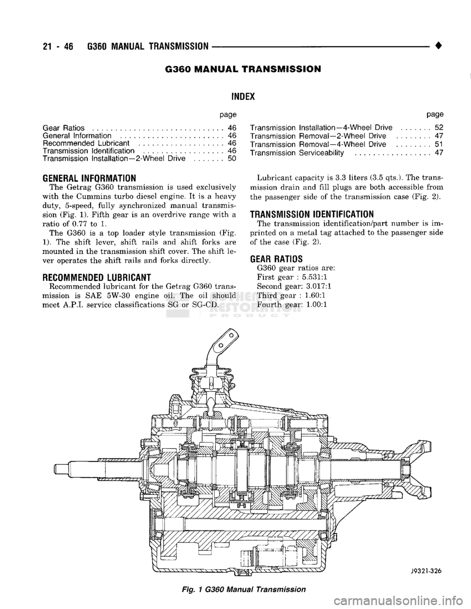
The Getrag G360 transmission
is
used exclusively
with
the
Cummins turbo diesel engine.
It is a
heavy duty, 5-speed, fully synchronized manual transmission
(Fig.
1).
Fifth gear
is an
overdrive range with
a
ratio
of
0.77
to 1.
The G360
is a top
loader style transmission
(Fig.
1).
The
shift lever, shift rails
and
shift forks
are
mounted
in the
transmission shift cover.
The
shift
le
ver operates
the
shift rails
and
forks directly.
RECOMMENDED
LUBRICANT
Recommended lubricant
for the
Getrag G360 trans
mission
is SAE
5W-30 engine
oil. The oil
should meet A.P.I, service classifications
SG or
SG-CD.
page
Transmission
Installation—4-Wheel
Drive
.......
52
Transmission Removal—2-Wheel
Drive
........
47
Transmission Removal—4-Wheel
Drive
51
Transmission
Serviceability
47
Lubricant capacity
is 3.3
liters
(3.5
qts.).
The
trans
mission drain
and
fill plugs
are
both accessible from
the passenger side
of
the
transmission case
(Fig.
2).
TRANSMISSION
IDENTIFICATION
The transmission identification/part number
is im
printed
on a
metal
tag
attached
to the
passenger side of
the
case
(Fig.
2).
GEAR
RATIOS
G360 gear ratios
are:
First gear
:
5.531:1 Second gear: 3.017:1
Third gear
:
1.60:1
Fourth gear:
1.00:1
Fig.
1
G360 Manual
Transmission
Page 1078 of 1502

•
AUTOMATIC
TRANSMISSION—32RH/3SRH/37RH/42RH/48RH
21 - 77
Flow
Control And Lubrication
The manual valve is operated by the gearshift link
age and provides the operating range selected by the
driver.
The 1-2 shift valve provides automatic 1-2 or 2-1
shifts and the 2-3 shift valve provides automatic 2-3
or 3-2 shifts.
The kickdown valve provides forced 3-2 or 3-1
downshifts depending on vehicle speed. Downshifts
occur when the throttle is opened beyond downshift
detent position which is just before wide open throt
tle.
The 2-3 valve throttle pressure plug provides 3-2
downshifts with varying throttle openings and de
pending on vehicle speed.
The 1-2 shift control valve transmits 1-2 shift pres
sure to the accumulator piston to control kickdown
band capacity on 1-2 upshifts and 3-2 downshifts.
The limit valve determines maximum speed at
which a 3-2 part throttle kickdown can be made. Some transmissions do not have the limit valve and
maximum speed for a 3-2 kickdown is at the detent
position.
The shuttle valve has two functions. First is fast
front band release and smooth engagement during "lift foot" 2-3 upshifts. Second is to regulate front
clutch release and band application during 3-2 down
shifts.
The converter clutch valve applies the converter
modulated clutch when supplied with line pressure through the converter clutch solenoid. The solenoid is
controlled by and connected to the powertrain control module through a connector in the transmission case.
Electronic control of converter clutch engagement
includes disengagement at closed throttle during
warmup and during part throttle acceleration. Non- converter clutch transmissions have a threaded plug at the rear of the transmission case in place of the
solenoid wiring connector.
The fail safe valve restricts feed to the converter
clutch if front clutch pressure drops. It permits clutch
engagement only in direct (third) gear and provides
fast clutch release during kickdown.
The switch valve directs apply fluid pressure to the
converter clutch in one position and releases it in the
opposite position. It also directs oil to the cooling and
lube circuits. The switch valve regulates oil pressure
to the torque converter by limiting maximum oil
pressure to 130 psi.
Clutch/Band
Application The front/rear clutch pistons and servo pistons are
actuated by line pressure. When line pressure is re
moved, the pistons are released by spring tension.
On 2-3 upshifts, the front servo piston is released
by spring tension and hydraulic pressure. The accu mulator controls hydraulic pressure on the apply side
of the front servo during 1-2 upshifts and at all
throttle openings.
Page 1104 of 1502
•
AUTOMATIC
TRANSMISSION—32RH/36RH/37RH/42RH/46RH
21-103
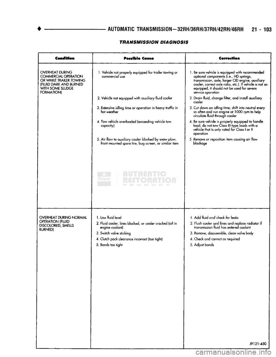
TRANSMISSION DIAGNOSIS
Condition
Possible
Couso
Correction
OVERHEAT
DURING
COMMERCIAL
OPERATION
OR
WHILE
TRAILER
TOWING
(FLUID
DARK
AND
BURNED
WITH
SOME
SLUDGE
FORMATION)
1.
Vehicle not properly equipped for
trailer
towing or
commercial use
2. Vehicle not equipped
with
auxiliary fluid cooler
3.
Extensive idling
time
or operation in heavy
traffic
in hot weather
4. Tow vehicle overloaded (exceeding vehicle tow capacity)
5. Air flow to auxiliary cooler blocked by snow plow,
front
mounted spare
tire,
bug screen, or similar
item
1.
Be sure vehicle is equipped
with
recommended
optional components
(i.e.,
HD
springs,
transmission,
axle, larger CID engine, auxiliary cooler, correct axle ratio, etc.). If vehicle is not so
equipped, it should not be used for severe
service operation
2. Drain fluid, change
filter,
and install auxiliary cooler
3.
Cut down on idling time; shift into
neutral
every
so
often and run engine at 1000 rpm to help
circulate fluid through cooler
4. Be sure vehicle is properly equipped to handle
load;
do not tow
Class
Ill-type loads
with
a
vehicle
that
is only
rated
for
Class
1
or II operation
5.
Remove or reposition
item
causing
air flow
blockage
OVERHEAT
DURING
NORMAL
OPERATION
(FLUID
DISCOLORED,
SMELLS
BURNED)
1.
Low
fluid
level
2. Fluid cooler, lines blocked, or cooler cracked (oil in engine coolant)
3.
Switch valve sticking
4. Clutch pack clearance incorrect (too tight)
5.
Bands
too tight 1. Add
fluid
and check for leaks
2. Flush cooler and lines and replace radiator if
transmission
fluid has
entered
coolant
3.
Remove,
disassemble,
clean valve body
4. Check and correct as required
5. Adjust bands
J9121-450
Page 1371 of 1502
22 - 2
WHEELS
AND
TIRES
•
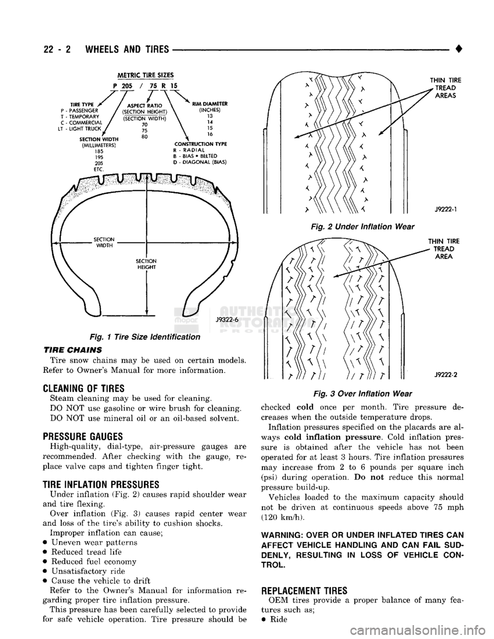
METRIC
TIRE
SIZES
P
205 / 75 I 15
J9322-6
Fig.
1
Tire
Size
identification
TIRE
CHAINS
Tire snow chains may be used on certain models.
Refer to Owner's Manual for more information.
CLEANING
OF
TIRES
Steam cleaning may be used for cleaning.
DO NOT use gasoline or wire brush for cleaning.
DO NOT use mineral oil or an oil-based solvent.
PRESSURE GAUGES
High-quality, dial-type, air-pressure gauges are
recommended. After checking with the gauge, re
place valve caps and tighten finger tight.
TIRE
INFLATION
PRESSURES
Under inflation (Fig. 2) causes rapid shoulder wear
and tire flexing. Over inflation (Fig. 3) causes rapid center wear
and loss of the tire's ability to cushion shocks. Improper inflation can cause;
• Uneven wear patterns
• Reduced tread life
• Reduced fuel economy
• Unsatisfactory ride
• Cause the vehicle to drift Refer to the Owner's Manual for information re
garding proper tire inflation pressure. This pressure has been carefully selected to provide
for safe vehicle operation. Tire pressure should be
Fig.
2
Under
infiation
Wear
Fig.
3
Over
Infiation
Wear
checked cold once per month. Tire pressure de creases when the outside temperature drops.
Inflation pressures specified on the placards are al
ways cold
inflation
pressure. Cold inflation pres sure is obtained after the vehicle has not been
operated for at least 3 hours. Tire inflation pressures may increase from 2 to 6 pounds per square inch (psi) during operation. Do not reduce this normal
pressure build-up.
Vehicles loaded to the maximum capacity should
not be driven at continuous speeds above 75 mph (120 km/h).
WARNING: OVER
OR
UNDER INFLATED TIRES
CAN
AFFECT VEHICLE HANDLING
AND CAN
FAIL
SUD DENLY, RESULTING
IN
LOSS
OF
VEHICLE CON
TROL
REPLACEMENT TIRES
OEM tires provide a proper balance of many fea
tures such as; • Ride
Page 1375 of 1502
22 - e
WHEELS
AND
TIRES
• WHEELS
GENERAL
INFORMATION
Original equipment wheels are designed for all
loads up to the specified Maximum Vehicle Capacity. All models use steel or cast aluminum drop center
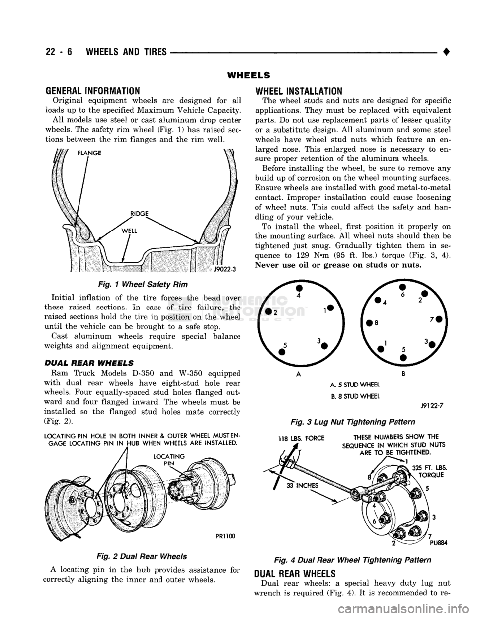
wheels. The safety rim wheel (Fig. 1) has raised sec
tions between the rim flanges and the rim well.
S
J9022-3
Fig.
1
Wheel
Safety Rim Initial inflation of the tire forces the bead over
these raised sections. In case of tire failure, the
raised sections hold the tire in position on the wheel
until the vehicle can be brought to a safe stop.
Cast aluminum wheels require special balance
weights and alignment equipment.
DUAL
REAR
WHEELS
Ram Truck Models
D-350
and
W-350
equipped
with dual rear wheels have eight-stud hole rear
wheels. Four equally-spaced stud holes flanged out
ward and four flanged inward. The wheels must be
installed so the flanged stud holes mate correctly (Fig. 2).
LOCATING PIN HOLE
IN
BOTH INNER
&
OUTER WHEEL
MUST
EN
GAGE
LOCATING PIN
IN
HUB WHEN WHEELS ARE INSTALLED.
PR1100
Fig.
2
Dual
Rear
Wheels
A locating pin in the hub provides assistance for
correctly aligning the inner and outer wheels.
WHEEL
INSTALLATION
The wheel studs and nuts are designed for specific
applications. They must be replaced with equivalent
parts.
Do not use replacement parts of lesser quality or a substitute design. All aluminum and some steel
wheels have wheel stud nuts which feature an en larged nose. This enlarged nose is necessary to en
sure proper retention of the aluminum wheels. Before installing the wheel, be sure to remove any
build up of corrosion on the wheel mounting surfaces. Ensure wheels are installed with good metal-to-metal contact. Improper installation could cause loosening
of wheel nuts. This could affect the safety and han
dling of your vehicle. To install the wheel, first position it properly on
the mounting surface. All wheel nuts should then be
tightened just snug. Gradually tighten them in se
quence to 129 N-m (95 ft. lbs.) torque (Fig. 3, 4).
Never use oil or grease on studs or nuts.
A. 5
STUD
WHEEL
B.
8
STUD
WHEEL
J9122-7
Fig.
3 Lug Nut Tightening
Pattern
118 LBS. FORCE THESE NUMBERS SHOW THE
SEQUENCE
IN
WHICH STUD NUTS
ARE
TO BE TIGHTENED.
FT. LBS.
TORQUE PU884
Fig.
4
Dual
Rear
Wheel
Tightening
Pattern
DUAL
REAR WHEELS
Dual rear wheels: a special heavy duty lug nut
wrench is required (Fig. 4). It is recommended to re-
Page 1445 of 1502
24 - 8
HEATING
AND AIR
CONDITIONING
• (e) If compressor clutch cycles 3 to 10 times per
minute with temperature between 20°C-32°C (68°F-
90°F),
the cycling switch is normal. If the compressor
clutch fails to engage, check for continuity in the elec
trical circuit. Above 32°C (90°F) the compressor clutch
may be continuously engaged (non-cycling) due to the
high heat load. This condition is normal.
(4)
Refer to the Evaporator Heater Assembly for
the Removal/Installation procedures.
TESTING
THE
SYSTEM
FOR
LEAKS
If the air conditioning system is not cooling properly,
check that the refrigerant system is fully charged with
R-12.
Follow the procedures in the Sight Glass Refrig
erant Level Test section of this group.
If the refrigerant system is empty or low in refrig
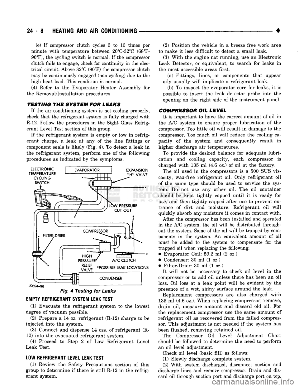
erant charge, a leak at any of the line fittings or
component seals is likely (Fig. 4). To detect a leak in
the refrigerant system, perform one of the following
procedures as indicated by the symptoms.
ELECTRONIC
TEMPERATURE CYCLING
SWITCH
EXPANSION
"H"
VALVE
J9324-96
Fig.
4 Testing for
Leaks
EMPTY REFRIGERANT SYSTEM LEAK TEST
(1) Evacuate the refrigerant system to the lowest
degree of vacuum possible.
(2) Prepare a 14 oz. refrigerant (R-12) charge to be
injected into the system. (3) Connect and dispense 14 ozs. of refrigerant (R-
12) into the evacuated refrigerant system, (4) Proceed to Step 2 of Low Refrigerant Level
Leak Test.
LOW REFRIGERANT LEVEL LEAK TEST
(1) Review the Safety Precautions section of this
group to determine if there is still R-12 in the refrig
erant system. (2) Position the vehicle in a breeze free work area
to make it less difficult to detect a small leak. (3) With the engine not running, use an Electronic
Leak Detector, or equivalent, to search for leaks in
the most accessible areas first.
(a) Fittings, lines, or components that appear
oily usually will implicate a refrigerant leak.
(b) To inspect the evaporator core for leaks, it is
possible to insert the leak detector probe into the opening on the right side of the instrument panel.
COMPRESSOR OIL LEVEL It is important to have the correct amount of oil in
the A/C system to ensure proper lubrication of the compressor. Too little oil will result in damage to the
compressor. Too much oil will reduce the cooling ca
pacity of the system and consequently result in
higher discharge air temperatures.
To provide the desired balance for adequate lubri
cation and cooling capacity, each compressor is
charged with 135 ml (4.6 oz.) of oil at the factory.
The oil used in the compressors is a 500 SUS vis
cosity, wax-free refrigerant oil. Only refrigerant oil of the same type should be used to service the sys
tem. Do not use any other oil. The oil container should be kept tightly capped until it is ready for
use,
and then tightly capped after use to prevent en
trance of dirt and moisture. Refrigerant oil will quickly absorb any moisture it comes in contact with.
After the compressor has been installed and operated
in the A/C system, the oil will be distributed through
out the system. Some of the oil will be trapped by com
ponents in the system. An equivalent amount of oil
must be added to the system to compensate for the
trapped oil when replacing the following: • Evaporator Coil: 59.2 ml (2 oz.)
• Condenser: 30 ml (1 oz.)
• Filter-Drier: 30 ml (1 oz.) It will not be necessary to check oil level in the
compressor or to add oil unless there has been an oil
loss.
Oil loss at a leak point will be evident by the
presence of a wet, shiny surface around the leak. Replacement compressors are also charged with
135 ml (4.6 oz.). When replacing compressor; remove,
drain oil, measure amount and discard old oil. For
the replacement compressor use the same amount of refrigerant oil as recovered from the failed compressor. This adjustment is not needed if the system has
been flushed, removing retained oil. The Compressor Oil Level Adjustment Chart
should be followed to determine the need to perform
an oil level adjustment. Check oil level (basic fill) as follows: (1) Slowly discharge complete system.
(2) With system discharged, disconnect suction and
discharge lines and remove compressor. Drain and dis card oil through suction port and discharge port on top.
Page 1447 of 1502
24 - 10
HEATING
AND AIR
CONDITIONING
•
(3) Add 50 ml (1.7 oz.) of clean refrigerant oil
through the suction port.
(4) Install compressor.
(5) Install the suction and discharge lines to the
compressor. Use new gaskets to prevent leakage.
Tighten the line nuts to 23 N*m (200 in. lbs.) torque.
(6)
Evacuate and charge system.
OVER-ALL
PERFORMANCE
TEST
Humidity has an important bearing on the temper
ature of the air delivered to the vehicle's interior.
This is true of all air conditioning systems It is im
portant to understand the effect humidity has on the
performance of the system. When humidity is high,
the evaporator has to perform a double duty. It must lower the air temperature and the temperature of the
moisture carried in the air. Condensing the moisture
in the air transfers a great deal of heat energy into
the evaporator fins and tubing. This reduces the amount of heat the evaporator can absorb from the
air.
Evaporator capacity used to reduce the amount of
moisture in the air is not wasted. Wringing some of
the moisture out of the air entering the vehicle adds
to the comfort of the passengers. However, an owner may expect too much from their air conditioning sys
tem on humid days. A performance test is the best
way to determine whether or not the system is per
forming up to standard. This test also provides valu able clues to the possible cause of trouble.
To perform the test the air temperature in the test
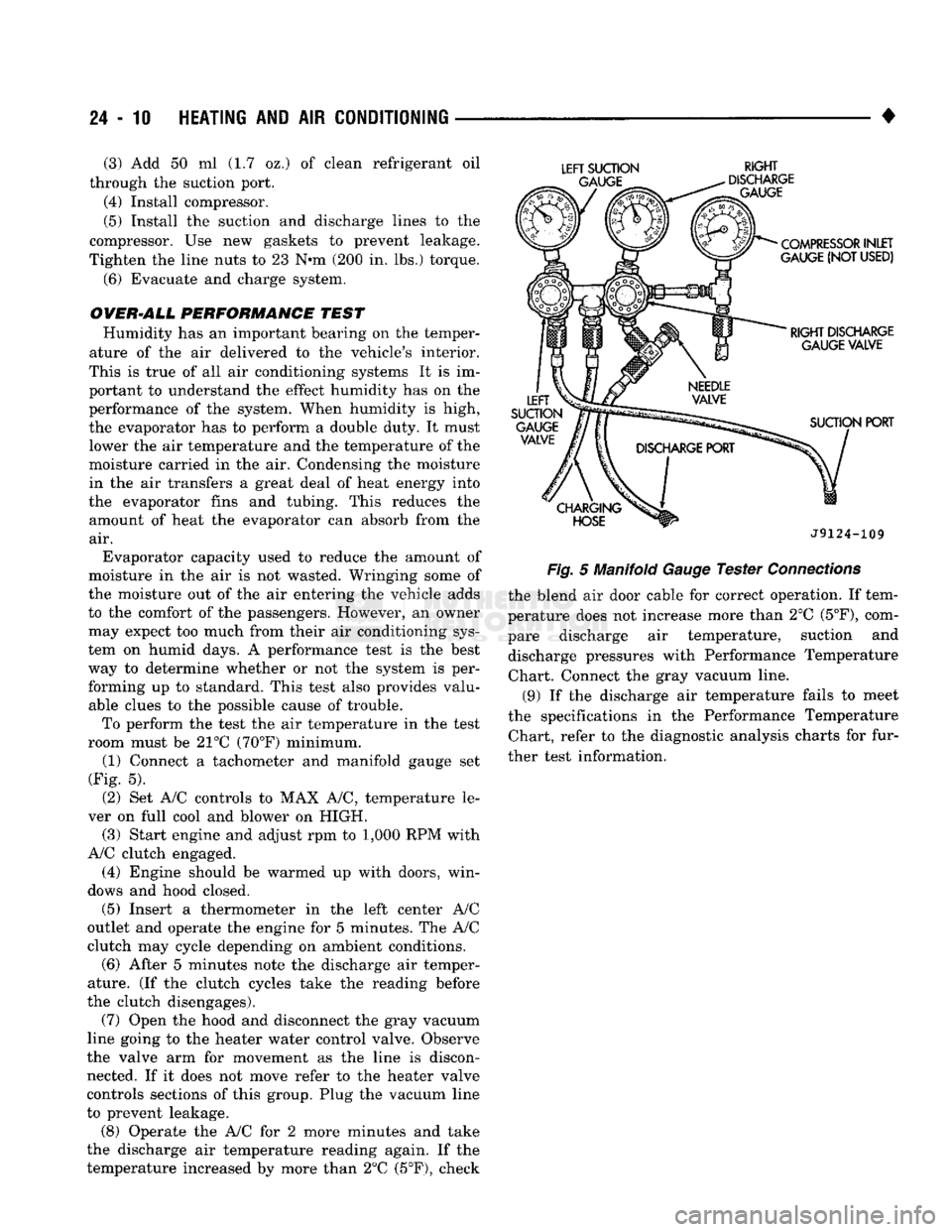
room must be 21°C (70°F) minimum. (1) Connect a tachometer and manifold gauge set
(Fig. 5).
(2) Set A/C controls to MAX A/C, temperature le
ver on full cool and blower on HIGH. (3) Start engine and adjust rpm to 1,000 RPM with
A/C clutch engaged.
(4) Engine should be warmed up with doors, win
dows and hood closed.
(5)
Insert a thermometer in the left center A/C
outlet and operate the engine for 5 minutes. The A/C
clutch may cycle depending on ambient conditions.
(6)
After 5 minutes note the discharge air temper
ature. (If the clutch cycles take the reading before
the clutch disengages).
(7) Open the hood and disconnect the gray vacuum
line going to the heater water control valve. Observe
the valve arm for movement as the line is discon nected. If it does not move refer to the heater valve
controls sections of this group. Plug the vacuum line
to prevent leakage.
(8) Operate the A/C for 2 more minutes and take
the discharge air temperature reading again. If the
temperature increased by more than 2°C (5°F), check
LEFT
SUCTION
RIGHT
J9124-109
Fig.
5 Manifold
Gauge
Tester
Connections
the blend air door cable for correct operation. If tem
perature does not increase more than 2°C
(5°F),
com
pare discharge air temperature, suction and discharge pressures with Performance Temperature Chart. Connect the gray vacuum line.
(9) If the discharge air temperature fails to meet
the specifications in the Performance Temperature Chart, refer to the diagnostic analysis charts for fur
ther test information.